Efficient Home Security and Management
using Internet of Things
Prasuryya Priyadarshan
UG Student(3rd Year), Department of Computer Science and Engineering, Chandigarh University, Punjab, India
ABSTRACT: Internet of things (IOT) has become a very important field of technology that has eased human labor in many aspects and has promoted the automation of different tasks. Home security and management is another application of IOT realized by this project and different technological and practical aspects of the project are discussed in this paper.
KEYWORDS: RFID, microprocessor.
I. INTRODUCTION
Internet of things is the emerging field of technology that has made the most efficient use of machine automation for the execution of different human activities. It basically is the real time application of programming to mechanical devices. It administers the functionality of different sensors by using a combination of microprocessors. These sensors help in the control of various devices by the realisation of certain electrical circuits. It connects different devices using the internet. [1]
The combination of microprocessors can be made as per requirement or such ready-made microprocessor boards are available for a wide range of uses. The most commonly used board is the Arduino series of boards. Arduino UNO is the board used for the implementation of this project.
RFID is a radiofrequency identification sensor which basically performs the function of authentication of a particular card/ tag recognised by the RFID sensor and the unrecognised cards/tags are denied authentication. The functionality of the RFID module is realised in this project for the application of home security and automation. [2]
II. THEPROBLEM
Home security forms a very integral part of the day to day lives of the common people and so is automation of the electrical components in the house. [3] Automation of the electrical components can promote electricity conservation and also reduce human effort which can be understood by the explanation of the working of the project later in this paper.
Thus, we can see that the main concern here is to make a cheap and efficient security system that will at the same time administer the electrical components of the house in a way which will allow the user to run the electrical appliances only after authorized access into the house.
III. THE DEVICE
The device will basically administer security and automation of electrical appliances. A prototype model has been designed to highlight the functioning of the said system. The model puts light on both the security and automation features of the device.
Arduino UNO: The Arduino Uno is a board consisting of microprocessors also known as a microcontroller board. Number of digital input/output pins in this board is 14 and analog pins are 6 in number. It has all the components needed for the functioning of the microcontroller board. It can be powered by using an USB cable or a DC supply. This board is used to implement computer programming in our appliances. It basically converts the computer program into electrical signals which makes the appliances or devices respond as instructed by the program. [4]
Fig. 1 Arduino Uno Board
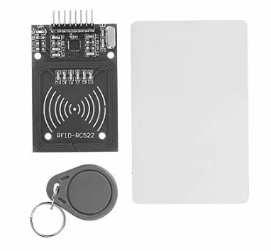
RFID: It is a radiofrequency identification sensor. It has two components, a RFID sensor/reader and a RFID tag/card. Data in digital form is encoded inside the tag/card. This data contains information about the card/ tag and is unique for each card/tag. The data in the card/tag is read by the reader using radio waves. The radio waves are converted into usable data by the reader. Now, the data of authorized cards can be stored in a database which can be recognised by the reader and the other unrecognised cards are denied authentication. [2] RFID module can be seen in the figure below.
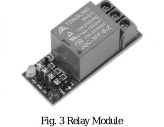
Relay: A relay is a switch that completes or breaks an electrical circuit. A relay when connected to an Arduino Board can open or close the circuit according to a condition as specified by the program in the board. It has two outputs, normally closed(NC) and normally open(NO). Thus, this forms an integral part in connecting the electrical appliances to the arduino board in order to make them operate as per the program. [4]
Fig. 3 Relay Module
Other Components: Other components used in the model are, a small fan and a LED light to demonstrate the working of electrical appliances, a servo motor to serve as a door latch operating motor, a battery, jumper wires.
Fig. 4: Servo Motor
B. Making of the device
Fig. 5 RFID reader to Arduino UNO connections
Apart from these, The IRQ pin remains not connected and the 3.3V and GND pins are connected to 3.3V and GND outputs of Arduino UNO respectively.
The relay module’s ‘IN’ pin is connected to a free output of the Arduino UNO board and the ‘GND’ pin is connected to the free GND output of Arduino UNO board. The ‘VCC’ of the relay module needs to be connected to a 5V supply of the board but at the same time, the servo motor also requires a 5V supply and the Arduino UNO board has only one 5V supply. Therefore, a shorted connection resulting in two 5V supplies from one 5V supply is made to connect both the servo motor and the relay module. The relay module is then connected to the fan and the light in parallel using a battery through NC or NO (as specified in the program). Similarly, the servo motor is attached with a door latch to demonstrate the security system.
After the connections are made, the program code is written. The code authorizes a specific card with a unique identification number. Then the connected pins for the servo motor and the relay module are defined and their conditions of operation are well stated by the code.
The code is then uploaded to the Arduino board using the USB cable.
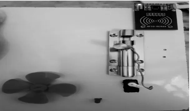
C. Working of the device
The basic concept behind the working of the model device is authorization of a specific card to make the output ports connected to the servo motor and the relay module active. This means, when the correct authorized card is scanned by the RFID reader, the Arduino outputs to which the relay and servo motor is connected, become active and the circuit gets complete, resulting in which, the servo motor rotates to open the door latch and at the same time the fan and the LED in the model become active. The servo motor is programmed to lock the door latch and the relay module is programmed to go inactive after 7.5 seconds, unless there is constant exposure to the authorized card. This prevents unnecessary wastage of electricity and at the same time makes home security efficient. In case, an unauthorized card is scanned by the reader, the circuit remains inactive and hence the door remains locked and the appliances turned off. Thus, it is a one card access to one’s home and automated working of the appliances with the same card.
D. Main functional part of the code
Fig. 6 Snapshot of code segment
As seen in the snapshot of the code segment, the Arduino digital output ports are activated and the servo motor is made to rotate by 70 degrees and after a delay of 7.5 seconds, the servo motor comes back to its original state and the pins are deactivated unless there is continued exposure of the reader to the authorized card.
IV.RESULTSANDDISCUSSION
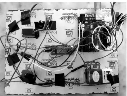
Fig. 8 Completed Connection of all elements
V.CONCLUSION
A prototype model of a device that makes one have complete access and control of the appliances of one’s home with just one card was made. This makes security much better than the traditional lock and key system, as the duplication of key isn’t possible. On the other hand, one doesn’t need to worry if he left his fan ON, as that isn’t possible without the authorized card in proximity of the RFID reader. Another point of advantage is the fact that, one doesn’t need to search for light switches in the dark, the card is in proximity of the reader, then the lights remain ON.
However, there is a limitation to this device. In case of loss of the authorized card, an alternate measure to gain access to the house needs to be developed, or one can authorize more than one card to act as backup and later just remove the lost card from the authorized list of cards in the database.
VI.FUTURESCOPE
A prototype model with limited functionalities was made. This device can be enhanced in number of ways. For instance, the functionalities of the card may be increased to playing some welcome music or adding a voice assistant to speak on grant or denial of access.
More than one RFID readers may be installed inside the house in multiple rooms with increased range of detection for automatic switching ON and OFF of lights when the card holder moves from one room to another.
The program code can also be modified for different operations when card remains in proximity for a longer period or for shorter periods.
REFERENCES
[1] JJ. A. Stankovic, "Research directions for the Internet of Things", IEEE Internet Things J., vol. 1, no. 1, pp. 3-9, Feb. 2014.. [2] I. M. Smith et al., "RFID and the inclusive model for the IoT", pp. 10-12, 2009.