NIMMELAPELLI, RAJA. FPGA Implementation of a SIP Message Processor. (Un-der the direction of Dr. Yannis Viniotis.)
by
Raja Nimmelapelli
A thesis submitted to the Graduate Faculty of North Carolina State University
in partial fulfillment of the requirements for the Degree of
Master of Science
Computer Engineering
Raleigh, North Carolina
2006
Approved By:
Dr. Gregory Byrd Dr. Adolfo Rodriguez
Dr. Yannis Viniotis Dr. William Rhett Davis
Biography
Acknowledgement
I sincerely thank my advisor, Dr.Yannis Viniotis for his invaluable guidance and sup-port through my graduate studies. I would like to sincerely thank him for providing me with the opportunity and encouraging me in pursuing my interests in the area of protocol hardware offload. I thank him for his constant support and encouragement. I am very grateful to Dr. W. Rhett Davis and Dr. Gregory Byrd for agreeing to be on my thesis committee and for the valuable feedback regarding the thesis document. I would like to thank Dr. Adolfo Rodriguez and Dr. Curtis Hrischuk, who spared time from their busy schedule at IBM, Raleigh to add value at the thesis defense.
I’d like to mention my family, who were always encouraging and supportive at all times. I am indebted to my sister and brother-in-law for providing me with this opportunity to pursue graduate studies.
Contents
List of Figures vii
List of Tables ix
1 Introduction and Literature Review 1
1.1 Importance of SIP . . . 1
1.2 Current Implementations of SIP . . . 2
1.2.1 Architecture of a SIP system . . . 3
1.2.2 SIP User Agent Client (UAC) . . . 4
1.2.3 SIP User Agent Server (UAS) . . . 5
1.2.4 Examples of a UAS . . . 5
1.3 Maximizing performance via hardware offload . . . 11
1.3.1 Issues with software network processing . . . 11
1.3.2 Industry examples: TCP Offload Engine (TOE) and SAN/iSCSI 11 1.3.3 SIP Offload Engine (SOE) . . . 13
1.4 Thesis organization . . . 14
2 SIP 15 2.1 Introduction . . . 15
2.2 SIP Grammar and its complexity . . . 15
2.2.1 Lexical analysis . . . 16
2.2.2 Syntactical Analysis . . . 17
2.3 SIP Messages . . . 18
2.3.1 SIP message format . . . 18
2.3.2 Types of messages . . . 18
2.4 SIP Header Fields . . . 20
2.4.1 Header field format . . . 20
2.4.2 Types of Header Fields . . . 20
3 Processor overhead savings analysis 22
3.1 Software approach to SIP message parsing . . . 22
3.2 Data structure for hardware offload . . . 23
3.3 Processor savings analysis . . . 27
4 Design Architecture 30 4.1 Introduction . . . 30
4.2 Block diagram and Explanation . . . 31
4.2.1 Delineator . . . 31
4.2.2 IP Checksum Calculator . . . 35
4.2.3 TCP Checksum Calculator . . . 36
4.2.4 SIP Byte Processor . . . 37
4.2.5 Buffer Write Controller . . . 39
4.3 Design Pipeline Explained . . . 40
5 Design Module Description 41 5.1 Module Delineator (delin) . . . 41
5.1.1 Pin Interface . . . 41
5.1.2 Architecture . . . 44
5.2 Module IP Checksum Calculator (ipchksum) . . . 53
5.2.1 Pin Interface . . . 53
5.2.2 Architecture . . . 54
5.3 Module TCP Checksum Calculator (tcpchksm) . . . 60
5.3.1 Pin Interface . . . 60
5.3.2 Architecture . . . 63
5.4 Module SIP Byte Processor (sipproc) . . . 68
5.4.1 Pin Interface . . . 68
5.4.2 Architecture . . . 70
5.5 Module Buffer Write Controller (bufwrctr) . . . 87
5.5.1 Pin Interface . . . 87
5.5.2 Architecture . . . 91
6 Software Simulation and Verification 96 6.1 Test Environment Description . . . 96
6.2 Testbench Architecture . . . 97
6.2.1 Module Packet Generator (pktgen) . . . 98
6.2.2 Module Reader (reader) . . . 99
6.3 Verification Test Plan . . . 101
6.3.1 Feature Tests . . . 102
7 FPGA Implementation 103
7.1 Choosing the Device . . . 103
7.2 Device Utilization Summary . . . 103
8 Future Work and Conclusion 105 8.1 Architecture Optimizations . . . 105
8.2 FPGA Implementation Optimizations . . . 105
8.2.1 Area Optimizations . . . 105
8.2.2 Timing Optimizations . . . 106
8.3 Feature Additions . . . 106
8.4 Verification . . . 107
8.5 Conclusion . . . 108
Bibliography 109
Appendix 111
A Sample Input File 112
List of Figures
1.1 Functional Architecture Block Diagram . . . 3
1.2 Functional location of a Registrar . . . 6
1.3 Functional location of a Proxy . . . 6
1.4 Functional location of a PSTN gateway . . . 7
1.5 Functional location of an H.323 gateway . . . 8
1.6 Functional location of a Redirect Server . . . 9
1.7 Functional location of a Media Server . . . 9
1.8 Functional location of a Conferencing Server . . . 10
2.1 Structure of a SIP message . . . 18
3.1 SIP Data Strcuture . . . 24
4.1 Block Diagram . . . 31
4.2 Delineator Implementation Diagram . . . 32
4.3 Format of the IP Header . . . 33
4.4 Format of the TCP Header . . . 34
4.5 IP Checksum Calculator Implementation Diagram . . . 35
4.6 TCP Checksum Calculator Implementation Diagram . . . 37
4.7 SIP Byte Processor Implementation Diagram . . . 38
4.8 Buffer Write Controller Implementation Diagram . . . 39
5.1 Interface waveform for Input FIFO . . . 44
5.2 Generation of Internal Registers . . . 45
5.3 Generation of Input FIFO Interface . . . 46
5.4 Internal counters and interface timing . . . 46
5.5 Generation of the byte counter . . . 47
5.6 Generation of the packet length register . . . 48
5.7 Generation of total IP header bytes register . . . 48
5.8 Generation of total TCP header bytes register . . . 49
5.9 Driving the IP Checksum Calculator Interface - 1 . . . 49
5.11 Driving the IP Checksum Calculator Interface - 3 . . . 50
5.12 Driving the TCP Checksum Calculator Interface - 1 . . . 51
5.13 Driving the TCP Checksum Calculator Interface - 2 . . . 51
5.14 Driving the TCP Checksum Calculator Interface - 3 . . . 52
5.15 Driving the SIP Byte Processor Interface . . . 52
5.16 Timing relation with Delineator Interface . . . 55
5.17 Timing relation with Buffer Write Controller Interface . . . 56
5.18 Generation of the IP byte select mux flag . . . 56
5.19 Generation of the IP byte accumulator . . . 57
5.20 Generation of the IP checksum register . . . 57
5.21 Generation of the received IP checksum register . . . 58
5.22 Generation of the IP Buffer Write Controller Interface - 1 . . . 58
5.23 Generation of the IP Buffer Write Controller Interface - 2 . . . 59
5.24 Timing relation with Delineator Interface . . . 64
5.25 Timing relation with Buffer Write Controller Interface . . . 64
5.26 Generation of the TCP byte select mux flag . . . 65
5.27 Generation of the TCP byte accumulator . . . 65
5.28 Generation of the TCP checksum register . . . 66
5.29 Generation of the received TCP checksum register . . . 66
5.30 Generation of the TCP Buffer Write Controller Interface - 1 . . . 67
5.31 Generation of the TCP Buffer Write Controller Interface - 2 . . . 67
5.32 Flowchart for the SIP Byte Processor . . . 70
5.33 SIP keyword search structure . . . 71
5.34 SIP keyword search flow . . . 72
5.35 State Machine Diagram . . . 73
5.36 Timing waveform for Delineator interface . . . 74
5.37 Generation of the byte status flags . . . 76
5.38 Generation of the processor current state . . . 77
5.39 Flowchart for encoding the SIP byte . . . 78
5.40 Generation of the search string . . . 79
5.41 Timing for the search operation . . . 80
5.42 Generation of the search string flags . . . 81
5.43 Generation of the Buffer Write Controller Interface . . . 86
5.44 Address space partitioning for the SIP Data Structure . . . 92
5.45 Timing Interface with the SIP Data Structure . . . 93
5.46 Memory Schematic . . . 94
5.47 Generation of the memory select flag . . . 94
6.1 Timing relation with Delineator Interface . . . 96
6.2 Architectural Block Diagram - Packet Generator Module . . . 98
List of Tables
3.1 Presence bit allocation for SIP Methods/Headers . . . 26
3.2 Request/Response bits . . . 27
3.3 Cycles required for an all-software approach . . . 28
3.4 Cycles required for a hardware-offloaded approach . . . 29
5.1 Interface with the system . . . 41
5.2 Interface with Packet FIFO . . . 42
5.3 Interface with IP Checksum Calculator . . . 42
5.4 Interface with TCP Checksum Calculator . . . 43
5.5 Interface with SIP Byte Processor . . . 44
5.6 Table of TCP/IP header fields extracted . . . 47
5.7 Interface with the system . . . 53
5.8 Interface with the Delineator . . . 53
5.9 Interface with the Buffer Write Controller . . . 54
5.10 Interface with the system . . . 60
5.11 Interface with the Buffer Write Controller . . . 61
5.12 Interface with Delineator . . . 62
5.13 Interface with the system . . . 68
5.14 Interface with Delineator . . . 68
5.15 Interface with Buffer Write Controller . . . 69
5.16 Delimiter Table . . . 75
5.17 Table for encoded character values . . . 78
5.18 Output codes for String1 . . . 82
5.19 Output codes for String2 . . . 83
5.20 Output codes for String3 . . . 84
5.21 Output codes for String4 . . . 85
5.22 Output codes for String5 . . . 85
5.23 Interface with the system . . . 87
5.24 Interface with the IP Checksum Calculator . . . 87
5.25 Interface with the TCP Checksum Calculator . . . 88
5.27 Interface with Memory 0 . . . 90
5.28 Interface with Memory 1 . . . 90
5.29 Interface with the external read requestor . . . 91
5.30 Table of sequence of write stimulus . . . 95
6.1 Interface with the system . . . 98
6.2 Interface with the DUT . . . 98
6.3 Interface with the system . . . 99
6.4 Interface with the DUT . . . 100
6.5 Table for feature tests . . . 102
6.6 Test result summary table . . . 102
Chapter 1
Introduction and Literature
Review
This chapter serves as an introduction to the main concepts behind the thesis: the Session Initiation Protocol (SIP) and hardware offloading.
1.1
Importance of SIP
Amongst a host of other compelling reasons, SIP gains importance for two reasons discussed in following paragraphs.
Sophisticated functions like multimedia and videoconferencing have enjoyed global appeal. Owing to the potentially large number of users, a robust distributed call management protocol needed to be developed, which would take care of user location, call setup, capability negotiation and call termination. To allow for easier scaling of the core network, the intelligence had to be kept away from the core and embedded in the end-points. SIP is a signaling protocol which provides this. It also allows run-time modification of the session parameters.
answering machine via phone or Internet. It enables personal mobility and provides the user with a greater degree of freedom. For example, a user could register from multiple locations and have the phone at all these locations ringing at the same time. The user could pick up the phone at whichever location he is and start the conversa-tion, without having to go through the trouble of updating his location whenever he moves.
1.2
Current Implementations of SIP
1.2.1
Architecture of a SIP system
UAS Proxy SIP Redirect SIP Registrar User Location Database SIP/PSTN Gateway PSTN Client Conferencing Server Media Server SIP/H.323 Gateway H.323 Client 1SIP User Agent Client : UAC SIP User Agent Server : UAS
2 n UAC UAC UAC UAS UAS UAS UAS SIP
Figure 1.1: Functional Architecture Block Diagram
Figure 1.1 depicts the architecture of a typical SIP system [1]. Components of a SIP system are called User Agents (UA’s). A UA is either a SIP User Agent Client (UAC) or a SIP User Agent Server. A SIP UAC is an entity which is a receiver of servi ces provided by the SIP system. A SIP UAS is an entity which in some way enables these services. The SIP UAC and UAS are discussed in more detail in sections 1.2.2 and 1.2.3. The User Location Database (ULD) stores the location information of the UAC’s. This database is queried when a particular UAC is to be located. There are non-SIP users (PSTN, H.323 clients) which enter the SIP system via gateways.
sequencing of messages between the UA’s and proper routing of requests between both of them. A dialog goes through three phases: the creation of the dialog, the processing of requests within the dialog and the termination of the dialog.
With respect to a dialog, communication between UA’s can occur:
1. Outside a dialog. This communication occurs when two UA’s are in the process of setting up a dialog.
2. Inside a dialog. This communication occurs when two UA’s have established a dialog.
1.2.2
SIP User Agent Client (UAC)
A UAC represents an end system which generates requests. These requests are usually the result of human actions like clicking the mouse button or other similar external stimulus. The requests are processed by the UAS and a reply is sent back to the UAC.
The request generation described above starts with the UAC initiating the estab-lishment of a dialog using the INVITE method. Upon receipt of a success code from the intended recipient, the dialog is said to be established. The session parameters can then be negotiated. Data transfer starts once the communicating UAC’s decide on the multimedia to be used in the session. To tear down the dialog, the BYE method is used by any one of the UAC’s.
1.2.3
SIP User Agent Server (UAS)
A UAS represents an end system which processes requests sent by the UAC. Based on the type of request received, the UAS executes procedures to generate a reply. This reply is then routed back to the UAC.
The UAS receives the requests from the UAC to establish a dialog. For this out-of-dialog request, there is a pre-defined set of procedures to be executed before the UAS can process this request and send a reply to establish a dialog. The UAS, in this order, needs to:
1. Authenticate the request.
2. Inspect the method in the request to see if supported by the UAS.
3. Inspect the header in the request, ignoring any malformed fields.
4. Inspect the content of the request, potentially rejecting the request for various reasons.
5. If all above inspections have passed, run method-specific procedures to generate a reply.
Once the success-reply generated by the UAS reaches the UAC, the dialog is said to be established. The UAS then processes any within-dialog requests like capability negotiations. Upon receving the BYE request, the dialog is torn down.
There are many forms a UAS can take in a SIP system, depending on the task it is supposed to perform. The various implementations are listed in section 1.2.4. Note that this is not a comprehensive list of all UAS implementations, only the major ones.
1.2.4
Examples of a UAS
1. Registrar
• Functional Diagram
SIP Request
UAC User Location
Database Registrar
(UAS)
User−Address Location Mapping
(REGISTER)
Figure 1.2: Functional location of a Registrar
• Inputs received
The Registrar accepts REGISTER inputs from UAC’s.
• Outputs generated
The Registrar processes the REGISTER request and updates the User Location Database with the binding information for that UAC.
2. Proxy
• Functional Diagram
SIP Request
(UAS)
Proxy (UAS)
SIP Response (Trying, OK)
SIP Request (INVITE)
SIP Response (Trying, OK)
DNS User Location Database
(REGISTER) SIP Request
UAC UAC
SIP Response
Proxy
• Inputs received
A Proxy receives SIP requests like INVITE which are to be routed to the destination UAC. It could also receive SIP responses from the destination which are to be relayed to the originating UAC.
• Outputs generated
The Proxy receives a SIP request (INVITE) at its input from the source UAC. It replicates this SIP request at the output and sends it to the target domain Proxy. It also receives SIP response messages(Trying, OK) from the destination UAC and replicates these at its output to the source UAC.
3. Gateways
Gateways exist to serve a strong business purpose. They act as a bridge between the new SIP components and existing legacy PSTN and H.323 equipment. With the help of gateways, end-to-end service can be provided seamlessly over these different protocols.
• PSTN gateway [5]
– Functional Diagram
PSTN PBX
(signaling)
PSTN Audio Content
PSTN Gateway
Call Content
PSTN Signaling
SIP Proxy
(UAS)
SIP Request
Figure 1.4: Functional location of a PSTN gateway
– Inputs received
– Outputs generated
The gateway outputs SIP signaling/content when it receives PSTN signaling/content at its input. It outputs PSTN signaling/content when it receives SIP signaling/content at its input.
• H.323 gateway [6]
– Functional Diagram
H.323 Gateway
(signaling)
SIP Proxy
(UAS) H.323 Proxy
H.323 Signaling SIP Request
Figure 1.5: Functional location of an H.323 gateway
– Inputs received
An H.323 gateway receives both signaling and content information. It receives H.323 signaling/data from the H.323 proxy which needs to be translated into the SIP domain. Conversely, it also receives SIP signaling/content which needs to be translated into the H.323 domain.
– Outputs generated
The gateway outputs SIP signaling/content when it receives H.323 sig-naling/content at its input. It outputs H.323 sigsig-naling/content when it receives SIP signaling/content at its input.
4. Redirect server
Alternate user address
(UAS)
SIP Request
(User Contact Address)
UAC Redirect Server
Figure 1.6: Functional location of a Redirect Server
• Inputs received
The Redirect server receives a SIP request at its input with a user contact address.
• Outputs generated
The Redirect server outputs a list of alternate addresses that user could potentially be available at.
5. Media server
• Functional Diagram
Proxy
Server Media Server
(UAS)
SIP Request (INVITE) SIP Response (OK)
RTSP ’SETUP’ Request
Welcome Message
RTSP
Figure 1.7: Functional location of a Media Server
• Inputs received
The Media server receives a SIP INVITE request at its input.
The Media server outputs a request to the Real Time Streaming Protocol (RTSP) server to obtain the welcome message and recording of voicemail. It sends an OK response to the originating UAC. The UAC then directly exchanges packets with the RTSP server.
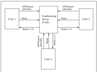
6. Conferencing server [7]
• Functional Diagram
Media (1,2)
(INVITE)
SIP Request (INVITE)
Conferencing Server (UAS)
SIP Request (INVITE)
UAC 1 UAC 2
UAC 3
Media Media
Media ( 2,3) Media (1,3)
Media
SIP Request
Figure 1.8: Functional location of a Conferencing Server
• Inputs received
The Conferencing server receives SIP INVITE requests from multiple UAC’s wishing to hold a conference. It also receives the conference media content from all UAC’s part of that conference.
• Outputs generated
1.3
Maximizing performance via hardware offload
1.3.1
Issues with software network processing
Networking software on a general workstation has to cater to a wide range of client applications. This results in simple and general purpose interfaces presented by the software to the hardware. The speed of the software interfaces is falling behind the speed with which the network hardware operates. It is common to now see Gigabit network cards deployed in general workstations. Even though the CPU clock speed is scaling, the high rate at which these cards present data to the networking software limits the communication performance and increases latency. Thus, the network software is a severe bottleneck for faster packet processing.
A solution which eases this bottleneck is to transfer some of the tasks done by the networking software onto dedicated hardware, an approach called hardware offloading. With this approach, there is a definite increase in performance as the hardware would process data much faster than software. More the tasks that are offloaded, faster the data processing becomes. Potentially, it is thus possible to match the network hardware speed and achieve maximum system performance.
Further sections exemplify hardware offloading by citing some industry proven techniques.
1.3.2
Industry examples: TCP Offload Engine (TOE) and
SAN/iSCSI
This section elaborates on how hardware offloading has resulted in performance enhancements. The two examples cited are TCP/IP and iSCSI offload.
1. TOE
however is not completely true. Although the TCP/IP processing speed has increased, the rate of increase is not parallel to the rate at which the CPU clock speed has scaled. The limiting factor is now the memory and I/O subsys-tems. TCP/IP is inherently a memory intensive operation, so the bad effects of memory latency are more pronounced. This latency results in wasted CPU idle cycles. So, a faster CPU only results in more idle cycles.
TCP/IP provides certain features which make it so popular for communication over the Internet. Some of these are reliable delivery, flow control and congestion control. However, to implement these features, a significant amount of software is required in the form of timers, counters, units that run algorithms, perform arithmetic and maintain the connection state. TCP/IP processing involves a good deal of memory. For example, the TCP connection state information is close to 256 bytes, so a TCP implementation which could potentially handle 32,000 connections needs 8 MB memory just to store the state information. So, it is clear that TCP/IP in software incurs a large software overhead and involves significant amount of memory. Both factors limit the performance of software TCP/IP.
Since the memory access time is a bottleneck for TCP/IP performance, multi-threading could be employed for better performance. Here, another thread is executed while the first one is waiting for data from the memory. Multithread-ing has two drawbacks. First, it is assumed that multiple threads are ready for execution at any point of time, which may not be the case for multiple high-bandwidth connections transferring large amounts of data. Another drawback is that multithreading requires more cache memory, which does not make it a cost-effective enhancement [7].
The advantages of TCP hardware offloading are highlighted by Terminator [10], a TCP offload engine developed by Chelsio Communications, Inc. It was found that during performance evaluation, for packet sizes of 1KB on a uni-directional 10 Gbps link, the throughput achieved with offload was four times that without offload.
2. iSCSI
The original SCSI protocol was used to communicate between devices connected to the internal and external computer busses. Internet SCSI [iSCSI] was de-veloped to enable large file transfers via blocks between any two computers connected to the Internet. iSCSI is used to enable Storage Area Networking (SAN).
iSCSI runs over TCP/IP and due to the overhead TCP incurs, is much slower than its SAN competitor, the Fibre Channel interface. However, the advantage iSCSI offers is that, unlike Fibre Channel, it uses TCP/IP/Ethernet, which makes it cheaper to install and maintain. So, in order to boost the performance and make it acceptable for SAN, the iSCSI and TCP protocols are offloaded onto hardware.
1.3.3
SIP Offload Engine (SOE)
processing of the protocol. We have seen how hardware offloading boosts processing speed in TCP and iSCSI. It is proposed to apply the same idea and offload the SIP protocol onto hardware.
How much of a protocol to offload is a complexity-performance tradeoff. If we offload more of the protocol, the complexity increases but so does the performance. To contain the complexity and still achieve significant performance boost, it is proposed to offload only the SIP message parsing onto hardware. Chapter 3 shows how such a limited offload can reduce CPU utilization by as much as 90%.
1.4
Thesis organization
Chapter 2
SIP
This chapter briefly describes the structure of the SIP protocol and explains its components.
2.1
Introduction
SIP follows a Request/Response type of transaction model. It follows a layered structure, with the syntax and encoding being the lowermost layer. It follows the Augmented Backnus Naur Format (ABNF) for encoding [11]. A SIP client would send a Request message to the server, which would reply with a Response message. The request/response message formats follow the standard track for Internet Message Format [12]. It follows the UTF-8 charset [13], which is the same as ASCII for 00-7F. The exact message types and formats are discussed in further sections.
2.2
SIP Grammar and its complexity
Grammar can be defined as a set of rules by which the protocol can be specified. It can be thought of as a tool to enable a protocol and ensure a uniform interpretation of a protocol by all its users.
make up the grammar.
Sections 2.2.1 and 2.2.2 discuss the reasons why SIP grammar could be considered as significantly complex to parse.
2.2.1
Lexical analysis
In a lexical perspective, the following points contribute to the complexity of SIP grammar [12].
1. Line length limit
The standard places a limit of 998 characters per line. This places a requirement on the software parser to be able to buffer so many characters at a stretch. This buffer comes at a cost for the software. In the SOE, the need for a buffer is eliminated by directly writing these bytes in memory, i.e no intermediate storage is required.
2. Random order of Header fields
Header fields are lines composed of a field name, followed by a semicolon (“:”), followed by a field body, and terminated by CRLF. The parser needs to be able to track the semicolon and CRLF delimiters. The characters till the semicolon need to be buffered seperately, as they form the header field name. The char-acters after the semicolon until the CRLF form the header value and are to be buffered seperately. The SOE performs the tracking of these delimiters by using a state machine based approach. This simplifies the seperation of the characters between delimiters. The header fields could occur in a random fashion, which make it difficult for the CPU to extract any particular header it is looking for.
3. Folding of header fields
a space or tab, we indicate that this is a continuation of the previous stream of characters. The software parser needs to be able to detect folded lines and “unfold” them correctly to extract the original character stream. The way the SOE tackles this issue is by detecting the CRLF-SP/HT sequence and deleting these occurences. The next stream of characters is seamlessly concatenated with the previous stream and treated as one stream. Note that no buffering is required in the SOE to cater to folding lines, which is where the advantage comes over a software implementation.
2.2.2
Syntactical Analysis
In a syntactical perspective, the following points contribute to the complexity of SIP grammar [12].
1. Special Characters
Quoted characters and special characters like ’/’ which are usually used as a delimiter can be used as a part of the message by enclosing it like ”/”.
2. Complex comments specification
A comment is a string of characters enclosed in parantheses. The comments could be nested within multiple lines via folding. There could be special char-acters present in the comment.
3. Multiple other specifications
There exist separate specifications for the Date and Time which only add to the complexity.
4. Multiple field definitions
2.3
SIP Messages
The SIP protocol enables end users to communicate with each other viamessages. These are pieces of information which are processed by the client/server. In its basic form, a message could either be a request sent from a client to a server or a reply from the server to the client.
2.3.1
SIP message format
A message consists of a start-line, one or more header fields, an empty line indi-cating the end of the header fields, and an optional message-body [2].This is shown in Figure 2.1.
message header field 2 ..
.. .. CRLF
message − body [optional]
start−line = Request−Line / Status−Line generic−message = start−line
message header field 1
Figure 2.1: Structure of a SIP message
2.3.2
Types of messages
A SIP message could either be a Request or a Response.
1. SIP Request Message
A request is recognized by the presence of a request-Line as the start-line. The request-line is of the format:
The method is an action associated with a session between end users. The methods and their function are listed below:
• REGISTER : Used to register contact information with the server.
• INVITE, ACK, CANCEL : Used for setting up sessions.
• BYE : Used to teminate a session.
The Request-URI is the recipient of the SIP message. The SIP Version is cur-rently SIP/2.0 and is to be included in all messages. The CRLF terminates the Request-Line.
2. SIP Response Message
A response is recognized by the presence of a status-line as the start-line. The status-line is of the format:
Status-Line = SIP-Version SP Status-code SP Reason-Phrase CRLF
The Status-Code represents the result of the action taken due to the request. The result of a request is categorized below:
(a) 100-199 : Request received, process in progress.
(b) 200-299 : The request was received, understood and accepted.
(c) 300-399 : Further action needs to be taken to complete processing of the request.
(d) 400-499 : The request cannot be processed at the server. Could be due to bad syntax.
(e) 500-599 : The server failed to process the request. The request could have been valid.
(f) 600-699 : Global failure. This request cannot be processed by any server.
Both the Request/Response messages may have multiple message headers. These headers are discussed further in section 2.4.
2.4
SIP Header Fields
SIP Header fields form a part of the SIP message. Each header conveys some information for the destination.
2.4.1
Header field format
The format for a SIP message header is shown. Each header field consists of a name followed by a colon (”:”) and the field value.
field-name : [ field-value ]
Note that the field value could extend over multiple lines as explained in section 2.2.1.
2.4.2
Types of Header Fields
The types of header fields can thought of to be based on the function performed by that header. Although this list may not be complete, the major header types are listed.
1. Originator fields : From, Destination, To
2. Routing fields: Via
3. Authentication: Proxy-Authenticate.
2.5
Requirements for parsing SIP messages
• Requirements for SIP Request-Line / Status-Line
1. The Request-Line should follow the format “Request line = Method name SP Request-URI SP SIP-Version CRLF”.
2. The status-Line should follow the format “Status Line = SIP-version SP Status-code SP Reason-phrase CRLF”.
3. No CR or LF allowed except at the end of the line.
4. No folding lines in any of the elements of the Request-Line
5. Request-URI must not contain unescaped spaces or control chars.
6. Request URI could also be a telephone URI, i.e a nummeric telephone number.
7. SIP-version must be SIP/2.0 in uppercase
• Requirements for the Header fields
Following is a list of requirements for parsing the header fields to correctly extract the header field names and their values.
1. The header is to be parsed in a <field name : field value>fashion.
2. Any number of whitespace allowed on either side of the semicolon in the above point.
3. Header fields can be extended over multiple lines, as long as each new line starts with a SP or HT.
4. Support multiple header field rows with the same field name, with the all field values specified in a comma seperated list.
5. Within a field value, any number of <parameter name=parameter value>
pairs can exist within a header field value.
Chapter 3
Processor overhead savings
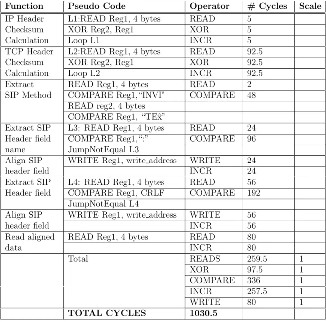
analysis
This chapter starts by briefly discussing the drawbacks of SIP message parsing in software. It then introduces the data structure used in the hardware implementation of the message parsing. An analysis is presented which shows how this proprietary data structure format allows us to achieve significant processor cycle savings. The in-tention of the analysis is to breakdown in a quantifiable terms, the difference between software and hardware processing of a SIP message. A part of the analysis consists of an imitation of a software implementation of a SIP message parsing module. The amount of software processing accounted for is considered as bare minimum for a single-CPU, without considering enhanced CPU features like multi-processor envi-ronments. The processing required is represented in terms of CPU cycles required. A similar analysis is done for the hardware approach to arrive at a number for the CPU cycles required. A comparison of these numbers gives us the CPU cycle savings between the two approaches.
3.1
Software approach to SIP message parsing
software code parsing the SIP message needs to extract all the header field names and their respective values. This could be a cumbersome task owing to the following two reasons:
1. Delimiters
The standard allows unrestricted use of delimiters such as spaces and tabs before, in-between and after the SIP header field names and values. Header field values could span multiple lines via the delimiter LWS, as explained in section 3. The software needs to recognize, use and eliminate these delimiters to make correct sense of the byte-stream.
2. Unrestricted order of field placement
There are certain SIP header fields related to routing (ex. TO,VIA) the CPU needs to examine before it starts to process the rest of the SIP message. Al-though the standard recommends the placement of the routing header fields at the beginning of the SIP message, it does not mandate it. So the CPU should allow for random placement of the header fields in the SIP message. This forces the CPU to parse the entire message before it even knows if it should process the message. In the SOE approach, the hardware would directly pass the routing headers to the CPU.
Section 3.2 elaborates on the format of the data structure used in the SOE. The format of this data structure is what allows the CPU savings, discussed in section 3.3.
3.2
Data structure for hardware offload
CPU is aware of these addresses and thus knows where to read header information from. An explanation of each of the elements of the data structure follows.
Field 50 Offset
’000’ REGISTER ’001’ INVITE ’010’ ACK ’011’ CANCEL ’100’ BYE 101’ OPTIONS
’1’ − REQUEST ’0’ − RESPONSE
0 14 15 29 30 31 32 IP Header TCP Header TCP/IP Checksum Pass bits
SIP Field Valid Reg 0 SIP Field Valid Reg 1
31 0
Bytes in header val Offset
31 17 9 8 0
resvd
Field 1 Offset REQ/RES Code & Offset 33
34
0 1 31
Bytes in header val Offset 31 30 28
resvd 0 8 9 17 resvd
IP cheksum result TCP checksum result
83 84
Method Code:
Figure 3.1: SIP Data Strcuture
1. IP Header
All the IP header bytes received are stored as in in locations 0 through 14.
2. TCP Header
All the TCP header bytes received are stored as in in locations 15 through 29.
3. TCP/IP checksum pass bits
a successful checksum match, i.e the calculated and the received checksums match. If this bit is cleared, it indicates that the checksums mismatch.
4. SIP Field Valid Registers 0,1
Table 3.1: Presence bit allocation for SIP Methods/Headers
Hex Addr
Bit # SIP Keyword Hex
Addr
Bit # SIP Keyword
31 0 Accept 31 1 Accept-Encoding
31 2 Accept-Language 31 3 Ack
31 4 Alert-Info 31 5 Allow
31 6 Authentication-Info 31 7 Authorization
31 8 Bye 31 9 Cancel
31 10 Call-ID 31 11 Call-Info
31 12 Contact 31 13 Content-Disposition
31 14 Content-Encoding 31 15 Content-Language
31 16 Content-Length 31 17 Content-Type
31 18 CSeq 31 19 Date
31 20 Error-Info 31 21 Expires
31 22 From 31 23 In-Reply-To
31 24 Invite 31 25 Max-Forwards
31 26 Min-Expires 31 27 MIME-Version
31 28 Options 31 29 Organization
31 30 Priority 31 31 Proxy-Authenticate
32 0 Proxy-Authorization 32 1 Proxy-Require
32 2 Register 32 3 Record-Route
32 4 Reply-To 32 5 Require
32 6 Retry-After 32 7 Route
32 8 Server 32 9 Subject
32 10 Supported 32 11 Timestamp
32 12 To 32 13 Unsupported
32 14 User-Agent 32 15 Via
32 16 Warning 32 17 WWW-Authenticate
5. Request/Response Type and Code
Table 3.2: Request/Response bits
0xAddress Bits Meaning
33 31 1- SIP Request, 0 - SIP Response
33 30-28 SIP Method. For bits 2-0, values are
“000” - REGISTER, “001” - INVITE, “010” - ACK, “011” - CANCEL, “100” - BYE and “101” - OPTIONS
33 17-9 The offset in the data structure where
the bytes start.
33 8-0 The number of bytes the REQ/RESP
occupies data structure starting from the above offset.
6. Method/Header Offset calculation
The bytes received in the Request/Response/Header are stored in the SIP Data Structure. These bytes can be retreived by using the offset provided. The offset tells us the start address and number of bytes stored for that method/header. Using this information and a global start address of 0x86, we can directly access the value of any method/header.
3.3
Processor savings analysis
The analysis starts by considering the following sample SIP packet. INVITE sip:[email protected] SIP/2.0
Via: SIP/2.0/UDP pc33.atlanta.com Max-Forwards: 70
To: Bob<sip:[email protected]>
From: Alice <sip:[email protected]>;tag=1928301774
The analysis then compares the CPU utilization involved in calculation of TCP/IP checksums and extraction of the SIP message headers for the following two methods:
• Complete software approach
The software does the TCP/IP checksum calculations and SIP header extrac-tion.
Table 3.3: Cycles required for an all-software approach
Function Pseudo Code Operator # Cycles Scale
IP Header L1:READ Reg1, 4 bytes READ 5
Checksum XOR Reg2, Reg1 XOR 5
Calculation Loop L1 INCR 5
TCP Header L2:READ Reg1, 4 bytes READ 92.5
Checksum XOR Reg2, Reg1 XOR 92.5
Calculation Loop L2 INCR 92.5
Extract READ Reg1, 4 bytes READ 2
SIP Method COMPARE Reg1,“INVI” COMPARE 48
READ reg2, 4 bytes COMPARE Reg1, “TEˆx”
Extract SIP L3: READ Reg1, 4 bytes READ 24
Header field COMPARE Reg1,“:” COMPARE 96
name JumpNotEqual L3
Align SIP WRITE Reg1, write address WRITE 24
header field INCR 24
Extract SIP L4: READ Reg1, 4 bytes READ 56
Header field COMPARE Reg1, CRLF COMPARE 192
JumpNotEqual L4
Align SIP WRITE Reg1, write address WRITE 56
header field INCR 56
Read aligned READ Reg1, 4 bytes READ 80
data INCR 80
Total READS 259.5 1
XOR 97.5 1
COMPARE 336 1
INCR 257.5 1
WRITE 80 1
• Hardware offload approach
The TCP/IP checksum and SIP header extraction functions are offloaded onto dedicated hardware. The software does trivial address calculations to obtain the header field values.
Table 3.4: Cycles required for a hardware-offloaded approach
Function Pseudo Code Operator # Cycles Scale
IP Header READ Reg1, 4 bytes READ 1
Checksum Calculation
TCP Header READ Reg1, 4 bytes READ 1
Checksum Calculation
Read READ Reg1, 4 bytes READ 1
SIP Method
Read SIP READ Reg1, 4 bytes READ 2
Header field READ Reg2, 4 bytes COMPARE 8
name COMPARE, Reg1, “1” INCR 2
COMPARE Reg2, “1”,
Read SIP ADD Base address, index READ 54
Header field READ Reg1, 4 bytes INCR 54
value ADD Field address, Reg1 ADD 2
L1: READ Reg1, 4 bytes COMPARE 6
COMPARE Field length,0 JumpNotEqual L1
Total READS 59 1
COMPARE 14 1
INCR 56 1
ADD 2 2
TOTAL CYCLES 133
Chapter 4
Design Architecture
4.1
Introduction
In chapter 3 we saw the potential savings the SOE could achieve. In this section we take a high level look at the design architecture. The block diagram will be discussed. Functions and implementation details of individual blocks will also be elaborated on. The design examines the incoming SIP/TCP/IP stream. The individual SIP, TCP header and IP header bytes are delineated and sent to dedicated processing blocks. Once the data is processed, each block writes its share of data to the SIP data structure. The order of write access to the SIP data structure is the IP block first, followed by the TCP block and then finally the SIP block. Once the SIP data structure is completed, it is assumed that a PCI device would read this data and write it to the system memory, where it would be examined by the CPU.
The packets at the input of the design could be expected to arrive in a non-stop fashion. To cater to this, a pipelined approach was taken at a block level so that the flow of packets is not interrupted. Further, no backpressure is exerted on the input FIFO. The architecture can be classified as cut-through, i.e the incoming packet is not stored before processing.
4.2
Block diagram and Explanation
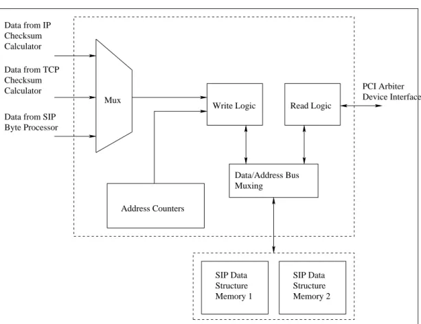
Write Calculator TCP Checksum Calculator IP Checksum SIP Byte Processor Delineator Controller Buffer Write TCP Header, Chksum Result SIP Structure Data Data Flow Control Flow Header Values,Indices SIP Data
Structure (Memory) Address Data Read, Write Fifo empty Fifo Read IP Byte Valid TCP Byte Valid Write
IP Header, Chksum result
Write SIP Byte
Valid
Read,Valid FIFO Data
Figure 4.1: Block Diagram
The above figure shows the block level implementation of the SIP Offload Engine. We shall discuss the functions and brief implementation in subsequent sections.
4.2.1
Delineator
The following sections list the functions and implementation of the Delineator block.
• Functions
1. Interfaces to a FIFO on the input side.
2. Examines incoming SIP/TCP/IP byte stream.
4. Routes IP, TCP, SIP bytes to the IP, TCP and SIP Processor blocks
5. Identifies the incoming TCP and IP checksum values, passes them to the respective blocks for checksum verification
• Implementation
TCP Checksum Interface
Logic
Byte Number Logic
IP Checksum Calculator Interface Logic
Logic Calculator Interface TCP Checksum
SIP Processor Interface Logic Input
FIFO
IP Checksum Calculator Interface
Processor Interface SIP Byte Calculator Interface FIFO
Figure 4.2: Delineator Implementation Diagram
1. Identifying IP bytes
An indication is received from the FIFO to flag the start of a new packet. This packet is the SIP/TCP/IP stream that needs to be processed.
IHL
Ver Type Of Ser Total Length Identification Flags Fragment Offset TTL Protocol Header Checksum
Source Address Destination Address
Options Padding 4 8 16 19 32
Figure 4.3: Format of the IP Header
Figure 4.3 shows the fields present in the IP Header. The first byte in this new stream marks the first IP header byte (Version & Internet Header Length). The Internet Header Length tells us how many successive bytes are going to be IP bytes. For example, if this value is 0101, it signifies that the next (5*4=20) bytes are IP header bytes. Accordingly, the next 20 bytes are flagged as IP Bytes. These bytes are processed by the IP Checksum calculator.
2. Identifying TCP Bytes
This value is calculated by the TCP Checksum Calculator.
TCP Length TCP Pseudo Header
Source Port Destination Port Sequence Number Acknowledgement Number
Offset Rsvd Flags Window
Checksum Urgent Pointer
Options Padding
Data
TCP Header
1 1617 32
IP Source Address IP Dest Address Zero PTCL
Figure 4.4: Format of the TCP Header
3. Identifying SIP Bytes
4.2.2
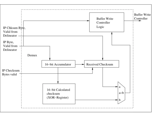
IP Checksum Calculator
The following sections list the functions and implementation of the IP Checksum Calculator Block.
• Functions
1. Calculate the checksum over the IP header bytes.
2. Compare the calculated checksum with the received checksum.
3. Deliver the IP header bytes and the checksum Pass/Fail result bit to the Buffer Write Controller
• Implementation
IP Chksum Byte,
checksum (XOR−Register)
Buffer Write Controller Logic
Controller Buffer Write
IP Byte, Valid from Delineator
16−bit Accumulator Received Checksum
b a a=b Demux
IP Checksum Bytes valid
Valid from Delineator
16−bit Calculated
The IP checksum calculator maintains a 16 bit XOR register. Every time 16 bits of IP header data are accumulated, they are XORed with the existing 16 bits of the XOR register. Once the last byte of the IP header comes in, the value in the XOR register is compared with the received checksum. Accordingly, a checksum Pass/Fail indication is determined. All received IP header bytes and the checksum result are written into the SIP data structure by the Buffer Write Controller.
4.2.3
TCP Checksum Calculator
The following sections list the functions and implementation of the TCP Checksum Calculator Block.
• Functions
1. Calculate the TCP checksum.
2. Compare the calculated checksum with the received checksum.
3. Deliver the TCP header bytes and the checksum Pass/Fail result bit to the Buffer Write Controller. Note that only the TCP header bytes are written to the SIP data structure. The TCP payload bytes are used for the checksum calculations.
• Implementation
TCP Byte,
checksum (XOR−Register)
Buffer Write Controller Logic
Controller Buffer Write
TCP Checksum Bytes valid
16−bit Accumulator Received Checksum
b a a=b Demux
Valid from Delineator
16−bit Calculated
Figure 4.6: TCP Checksum Calculator Implementation Diagram
4.2.4
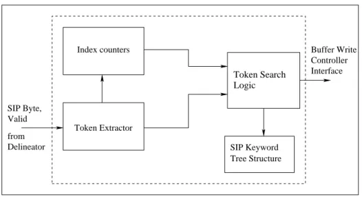
SIP Byte Processor
The following sections list the functions and implementation of the IP Checksum Calculator Block.
• Importance of the SIP Byte Processor The SIP Byte Processor is primarily responsible for recognizing valid SIP keywords from the incoming SIP byte stream. Its importance in the entire design stems from the fact that it generates most of the fields required in the SIP data structure. A significant percentage of the CPU overhead savings is effected by this module.
• Functions
2. Search for the validity of these tokens as SIP keywords.
3. Indicate the presence of validated keyword in the SIP data structure.
• Implementation
Index counters
Logic
SIP Keyword Tree Structure from
Delineator SIP Byte, Valid
Buffer Write Controller Interface
Token Extractor
Token Search
Figure 4.7: SIP Byte Processor Implementation Diagram
4.2.5
Buffer Write Controller
The following sections list the functions and implementation of the IP Checksum Calculator Block.
• Functions
1. Possesses exclusive write control over the SIP data structure.
2. Accepts for data from the potential write requestors. Writes this data to the SIP data structure.
• Implementation
Read Logic Byte Processor
Data from TCP Checksum Calculator Data from IP Checksum Calculator
Write Logic
SIP Data Structure Memory 2 SIP Data
Structure Memory 1
Data/Address Bus Muxing
PCI Arbiter Device Interface
Address Counters Mux
Data from SIP
A first come first serve approach is used to accept write requestor data to the memory. This approach is possible because each of the write requestors issue their requests at different points of time. First the IP checksum calculator would post its request, followed by the TCP checksum calculator and finally the SIP byte processor. The data to be written is multiplexed based on who the requestor is.
4.3
Design Pipeline Explained
The input can be considered as a continous flow of packets. One way to approach the design would be to first completely buffer the incoming packet, process it, then look at the next packet. In this case, there could be a situation where we would need to exert backpressure on the input and halt the packet flow. This would happen when a large packet is being processed while multiple small packets are coming in. It would not be a good idea to exert any backpressure on the input, as this would have repercussions all the way upstream to the Network Interface Card.
Chapter 5
Design Module Description
In section 4, we had a top-level look at a block-level architecture of the design. We saw the functions of the blocks and had a brief idea of how each block is implemented. The current section aims to provide more details. For each block, the pin interfaces with other bslocks and a detailed implementation description are given. This would include the FSM, data structures, arithmetic units and specific logic involved.
5.1
Module Delineator (
delin
)
This section and its subsection present a detailed description of the Delineator module. Section 5.1.1 presents the pin interfaces with blocks it interacts with. Section 5.1.2 describes its implementation in detail.
5.1.1
Pin Interface
This section describes the pin interfaces with the other blocks.
Table 5.1: Interface with the system
No. Pin Name Dirn. Width Description
1 reset IN 1 The async system reset.
Table 5.2: Interface with Packet FIFO
No. Pin Name Dirn. Width Description
1 fifo empty IN 1 Indicates the presence of data
in the FIFO
2 fifo data IN 9 Data read from the FIFO.
In-terpreted as 8 bit data byte and a 1 bit indication.
3 delin fifo read OUT 1 An indication that the
delin-eator has accepted the FIFO byte.
Table 5.3: Interface with IP Checksum Calculator
No. Pin Name Dirn. Width Description
1 delin startofpkt OUT 1 An indication to reset the
checksum registers.
2 delin ipbyte valid OUT 1 An indication that the current
byte is valid. The IP checksum calculator processes the byte only if this signal is set.
3 delin ip byte OUT 8 The byte to be processed.
4 delin ipchksm msbyte OUT 1 An indication that the current
byte is the IP checksum MS byte. The IP checksum calcu-lator needs these bytes to verify the checksum
4 delin ipchksm lsbyte OUT 1 An indication that the current
byte is the IP checksum LS byte.
6 delin last ipbyte OUT 1 An indication that the current
Table 5.4: Interface with TCP Checksum Calculator
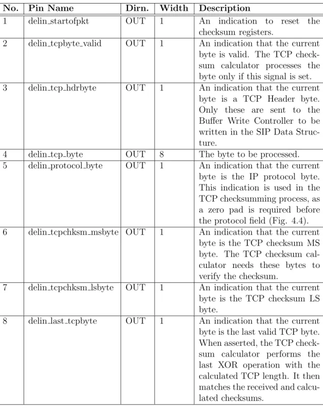
No. Pin Name Dirn. Width Description
1 delin startofpkt OUT 1 An indication to reset the
checksum registers.
2 delin tcpbyte valid OUT 1 An indication that the current
byte is valid. The TCP check-sum calculator processes the byte only if this signal is set.
3 delin tcp hdrbyte OUT 1 An indication that the current
byte is a TCP Header byte. Only these are sent to the Buffer Write Controller to be written in the SIP Data Struc-ture.
4 delin tcp byte OUT 8 The byte to be processed.
5 delin protocol byte OUT 1 An indication that the current
byte is the IP protocol byte. This indication is used in the TCP checksumming process, as a zero pad is required before the protocol field (Fig. 4.4).
6 delin tcpchksm msbyte OUT 1 An indication that the current
byte is the TCP checksum MS byte. The TCP checksum cal-culator needs these bytes to verify the checksum.
7 delin tcpchksm lsbyte OUT 1 An indication that the current
byte is the TCP checksum LS byte.
8 delin last tcpbyte OUT 1 An indication that the current
Table 5.5: Interface with SIP Byte Processor
No. Pin Name Dirn. Width Description
1 delin sipbyte valid OUT 1 An indication that the current
byte is valid. The SIP Byte processor processes the byte only if this signal is set.
2 delin sipbyte OUT 8 The byte to be processed.
5.1.2
Architecture
We will start this section by discussing the interface timing between the Delineator and the input FIFO. We will then proceed to elaborate on the hardware implemen-tation of the blocks in the logic schematic shown in 4.2.
• Input FIFO Interface Timing
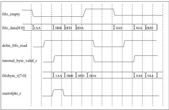
04A
fifo_empty fifo_data[8:0] delin_fifo_read internal_byte_valid_r fifobyte_r[7:0] startofpkt_r
1AA 0BB 0FD 0DA 0A8 04A 0DD
1AA 0BB 0FD 0DA 0A8
Figure 5.1 shows the behavior between the Delineator and the input FIFO. When fifo empty is sampled low, the data is read into an internal register. Upon each data unit registered by the Delineator,delin fifo read is asserted for a clock. Note that for the fifo data to be valid, fifo empty should be low and
delin fifo read should be high. Apart from the data byte, the fifo data delivers a bit indicating the start of a new packet. so the 9-bit fifo data is registered as separate information, i.efifobyte r[7:0] and startofpkt r. Both these registers are validated by internal byte valid r.
• Generation of Internal registers
Q
D Q
D Q D
fifobyte_r[7:0]
fifo_empty delin_fifo_read
internal_bytevalid_r fifo_data[8] startofpkt_r
fifo_data[7:0]
Figure 5.2: Generation of Internal Registers
• Generation of Input FIFO Interface
delin_fifo_read Q
fifo_empty D
Figure 5.3: Generation of Input FIFO Interface
• Timing Waveform for internal counters and output interfaces
20 delin_tcpbyte[7:0]
delin_sipbyte[7:0] delin_ipbyte[7:0]
14 BB 01 FF AC D5 E2 14 98 3A
fifobyte_r[7:0] internal_bytevalid_r startofpkt_r
bytenumber_r[15:0]
numof_iphdr_bytes_r[15:0]
pktlength_r[15:0]
delin_ipbyte_valid
delin_tcpbyte_valid
numof_tcphdr_bytes_r[5:0]
1 2 3 4 21 22 23 32 41 42
20
14 BB 01 FF AC D5 E2 14 98
01xx 01FF
delin_sipbyte_valid
Figure 5.4: Internal counters and interface timing
• Generation of the internal byte counter
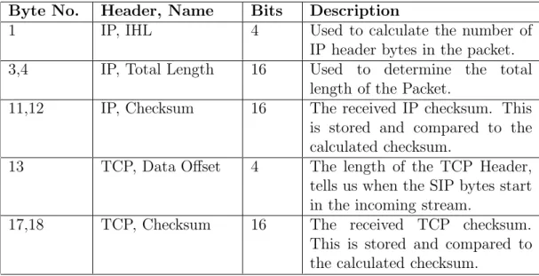
The byte counter bytenumber r is a 16-bit counter. It is cleared when a new packet arrives in the input FIFO, flagged bystartofpkt r. It is then incremented once for each byte read from the FIFO. Based on the value of this counter, fields of interest are extracted from the TCP and IP headers. A list of the fields and the reason why they are extracted is are given in table 5.6.
Table 5.6: Table of TCP/IP header fields extracted
Byte No. Header, Name Bits Description
1 IP, IHL 4 Used to calculate the number of
IP header bytes in the packet.
3,4 IP, Total Length 16 Used to determine the total
length of the Packet.
11,12 IP, Checksum 16 The received IP checksum. This
is stored and compared to the calculated checksum.
13 TCP, Data Offset 4 The length of the TCP Header,
tells us when the SIP bytes start in the incoming stream.
17,18 TCP, Checksum 16 The received TCP checksum.
This is stored and compared to the calculated checksum.
16’d2
D Q CE 1
0 + ’1’
startofpkt_r
internal_bytevalid_r
bytenumber_r[15:0]
• Generation of the total length, TCP & IP header byte registers
Depending on the value of bytenumber r, multiple required fields are locally registered.
16’d4
D Q
CE a=b
b a
fifodata_r[7:0] pktlength_r[15:8] bytenumber_r[15:0]
16’d3
D Q
CE a=b
b a fifodata_r[7:0] bytenumber_r[15:0]
pktlength_r[7:0]
Figure 5.6: Generation of the packet length register
Similarly, the number of TCP and IP header bytes in the current packet are locally registered. It is interesting to note that the location of the TCP header bytes depends on the number of IP header bytes present. These values are later on examined to determine the timing of the output interfaces to the next modules in the design.
(Left Shift by 2) − ’1’ D Q
CE
numof_iphdr_bytes_r[5:0]
startofpkt_r fifodata_r[7:4]
bytenumber_r[15:0]
D Q
CE a=b
b a numof_iphdr_bytes_r[5:0] + 6’d12
fifodata_r[7:4]
Left Shift by 2 numof_tcphdr_bytes_r[5:0]
Figure 5.8: Generation of total TCP header bytes register
• Driving the IP Checksum Calculator Interface
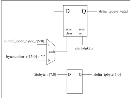
The following hardware diagrams elaborate on how the IP Checksum Calculator interface is driven, based on the local registers and counters. The hardware behind each output pin of the module, on that interface, is shown.
set
a=b b a
D Q
D
Q
fifobyte_r[7:0] delin_ipbyte[7:0] startofpkt_r
delin_ipbyte_valid
numof_iphdr_bytes_r[5:0] bytenumber_r[15:0] + ’1’
sync sync
clear
delin_startofpkt D Q
D Q a=b
b a numof_iphdr_bytes_r[5:0]
bytenumber_r[15:0]
delin_last_ipbyte
startofpkt_r
Figure 5.10: Driving the IP Checksum Calculator Interface - 2
delin_ip_checksum_lsbyte D Q
a=b b a bytenumber_r[15:0]
4’d11
delin_ip_checksum_msbyte
D Q a=b
b a bytenumber_r[15:0]
4’d12
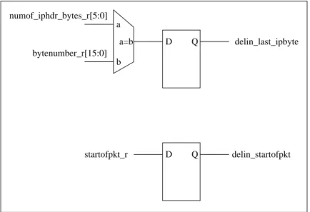
• Driving the TCP Checksum Calculator Interface
The following hardware diagrams elaborate on how the TP Checksum Calcula-tor interface is driven, based on the local registers and counters. Thes hardware behind each output pin of the module, on that interface, is shown.
numof_iphdr_bytes_r[5:0]
D Q
sync set
sync clear
a
b a=b
D Q delin_tcpbyte[7:0] fifobyte_r[7:0]
a=b b a
delin−tcpbyte−valid
pktlength_r[15:0]
bytenumber_r[15:0] + ’1’ bytenumber_r[15:0] + ’1’
Figure 5.12: Driving the TCP Checksum Calculator Interface - 1
delin_startofpkt D Q
D Q a=b
b a
delin_last_tcpbyte bytenumber_r[15:0]
pktlength_r[15:0]
startofpkt_r
delin_protocol_byte D Q a=b b a D Q a=b b a D Q a=b b a + 6’d17 numof_iphdr_bytes_r[5:0] bytenumber_r[15:0] numof_iphdr_bytes_r[5:0] + 6’d18 delin_tcp_checksum_msbyte delin_tcp_checksum_lsbyte bytenumber_r[15:0] bytenumber_r[15:0] 4’d8
Figure 5.14: Driving the TCP Checksum Calculator Interface - 3
• Driving the SIP Byte Processor Interface
Figure 5.15 shows the hardware behind the SIP byte processor Interface.
delin_sipbyte[7:0] D Q sync set sync clear numof_iphdr_bytes_r + numof_tcphdr_bytes_r a=b b a a a=b b delin_sipbyte_valid pktlength_r[15:0] bytenumber_r[15:0] bytenumber_r[15:0] + ’1’ + ’1’ D Q fifobyte_r[7:0]
5.2
Module IP Checksum Calculator (
ipchksum
)
This section presents a detailed description. Section 5.2.1 presents the pin inter-faces with connected blocks. Section 5.2.2 describes its implementation in detail.
5.2.1
Pin Interface
This section describes the pin interfaces with the other blocks.
Table 5.7: Interface with the system
No. Pin Name Dirn. Width Description
1 reset IN 1 The async system reset.
2 clk IN 1 The system clock.
Table 5.8: Interface with the Delineator
No. Pin Name Dirn. Width Description
1 delin startofpkt IN 1 An indication to reset the
checksum registers.
2 delin ipbyte valid IN 1 An indication that the current
byte is valid. The IP checksum calculator processes the byte only if this signal is set.
3 delin ip byte IN 8 The byte to be processed.
4 delin ipchksm msbyte IN 1 An indication that the current
byte is the IP checksum MS byte. The IP checksum calcu-lator needs these bytes to verify the checksum
4 delin ipchksm lsbyte IN 1 Flags the checksum LS byte.
6 delin last ipbyte IN 1 Indicates last valid IP byte. If
Table 5.9: Interface with the Buffer Write Controller
No. Pin Name Dirn. Width Description
1 ipchksum write OUT 1 An indication that the
cur-rent byte is a valid IP header byte. the Buffer Write Con-troller samples this valid and transfers this byte to the SIP data structure.
2 ipchksum byte OUT 8 The byte to be writtn to the
SIP data structure.
3 ipchksum result valid OUT 1 This signal is asserted once the
comparison between the calcu-lated checksum and received checksum is made. It is valid for one clock cycle.
4 ipchksum result bit OUT 1 This bit is looked at when
ipchksum result valid is as-serted. If high, it indicates that the received checksum matches with the calculated checksum. If low, it indicates a mismatch in the two checksums.
5.2.2
Architecture
We will start this section by the timing diagram between the Delineator input interface and their effect on registers internal to the IP Checksum Calculator. This is followed by the Buffer Write Controller timing diagram. We will then proceed to elaborate on the hardware implementation of the blocks in the logic schematic shown in 4.5.
• Timing waveform for interface with Delineator.
of the IP Header checksum. The incoming byte is either stored in the MS byte or the LS byte of ipbyte accum r, depending on the value of byte select r. After every second valid byte is received, i.e 16-bits have beel accumulated, an XOR operation is performed betweenipbyte accum r and a 16-bit XOR register,
ip checksum r. An exception to this continous XOR operation is when the input byte is a checksum byte. In this case, 0x00 is latched into ipbyte accum r. This is to be in accordance with the IP header checksum calculation method, which zeroes out the original checksum bytes when calculating the checksum over the rest of the IP header. A checksum byte at the input is signaled by either delin ipchksm msbyte or delin ipchksm lsbyte being asserted. After all the IP bytes are processed, a write strobe is passed to indicate the result of the checksum verification.
AC51
14 BB 01 FF AC FC D5 E2 BB AD 2C 98 3A
ACFC XOR 0A55 14BB
XOR 0000
01FF XOR 14BB
D5E2 XOR 1B38
delin_startofpkt delin_ipbyte_valid
delin_last_ipbyte
ipchksum_result_bit ipchksum_result_valid recvd_ip_chksum_r[15:0]
ip_checksum_r[15:0] ipbyte_accum_r[15:0]
delin_ipbyte[7:0]
byte_select_r
14xx 14BB 01BB 01FF ACFF ACFC D5FC D5E2
0000 14BB 0A55 1B38 AC51
ACxx
• Timing waveform for Buffer Write Controller Interface
Figure 5.17 shows the timing details of the Buffer Write Controller interface. Each byte that comes in from the Delineator has to be passed over to the Buffer Write Controller.
ipchksum_byte[7:0]
14 BB 01 FF D5 E2 BB AD 2C 98
14 BB 01 FF D5 E2 BB AD 2C 98
3A
delin_startofpkt delin_ipbyte_valid delin_ipbyte[7:0] ipchksum_write
Figure 5.17: Timing relation with Buffer Write Controller Interface
• Generation of byte select r
This is a flag which helps is directing bytes from the incoming stream into a 16-bit buffer. This buffer is further used for checksum calculations.
D Q CE 1
0
delin_ipbyte_valid ’1’
delin_startofpkt
byte_select_r
• Generation of ipbyte accum r[15:0]
This is a 16-bit accumulator which is used to store the IP bytes in pairs for checksum calculations.
ipbyte_accum_r[15:0]
D Q
delin_ipchksm_msbyte = ’1’ OR delin_ipchksm_lsbyte = ’1’
0
1
delin_ipbyte[7:0] & ipbyte_accum_r[7:0] delin_ipbyte[7:0] &
ipbyte_accum_r[7:0]
ipbyte_accum_r[15:8] & delin_ipbyte[7:0]
1 0 1
0
byte_select_r
delin_startofpkt 0000
Figure 5.19: Generation of the IP byte accumulator
• Generation of ip checksum r[15:0]
This is a 16-bit register which holds the result of the continous XOR operation.
CE
XOR
D
Q
sync clear
delin_ipbyte_valid OR delin_ipbyte_valid_r
1 0
ip_checksum_r[15:0] byte_select_r
ipbyte_accum_r[15:0]
delin_startofpkt
• Generation of recvd ip chksum r[15:0]
This is a 16-bit register, used to latch the two checksum bytes from the incoming IP byte stream. This value is used for comparison with the calculated checksum.
recvd_ip_chksum_r[7:0]
D Q
CE
D Q
CE delin_ipbyte[7:0]
delin_ipchksm_msbyte
delin_ipchksm_lsbyte delin_ipbyte[7:0]
recvd_ip_chksum_r[15:8]
Figure 5.21: Generation of the received IP checksum register
• Generation of the Buffer Write Controller Interface
Figures 5.22 and 5.23 shows the hardware behind the generation of the Buffer Write Controller Interface.
ipchksum_result_bit
D Q D Q D Q
D Q
a=b
b a
delin_last_ipbyte ipchksum_result_valid
ip_checksum_r[15:0]
recvd_ip_chksum_r[15:0]
ipchksum_byte[7:0] D Q
D Q
delin_ipbyte_valid ipchksum_write
delin_ipbyte[7:0]
5.3
Module TCP Checksum Calculator (
tcpchksm
)
This section and its subsection present a detailed description of the TCP Check-sum Calculator module. Section 5.3.1 presents the pin interfaces with blocks it inter-acts with. Section 5.3.2 describes its implementation in detail.
5.3.1
Pin Interface
This section describes the pin interfaces with the other blocks.
Table 5.10: Interface with the system
No. Pin Name Dirn. Width Description
1 reset IN 1 The async system reset.
Table 5.11: Interface with the Buffer Write Controller
No. Pin Name Dirn. Width Description
1 tcpchksm write OUT 1 An indication that the current
byte is a valid TCP byte. The Buffer Write Controller trans-fers this byte to the SIP data structure.
2 tcpchksm byte OUT 8 The byte to be written.
3 tcpchksm result valid OUT 1 This signal is asserted once the
comparison between the cal-culated checksum and received checksum is made.
4 tcpchksm result bit OUT 1 This bit is looked at when
ipchksum result valid is as-serted. If high, it indicates that the received checksum matches with the calculated checksum, else a mismatch.
5 tcpchksm last tcphdr byteOUT 1 An indication that the current
byte is the last TCP header
byte. This byte is used by