PERFORMANCE ANALYSIS OF LOAD FREQUENCY
CONTROL OF TWO AREA POWER SYSTEM USING
PSO BASED PID CONTROLLER
Umrana Saifi
1, Ameenuddin Ahmad
21
Student, M.Tech,
2Associate Prof., Department of Electrical & Electronics Engineering,
Al-falah University, (India)
ABSTRACT
The main objective of load frequency control & automatic generation control is to maintain the proper balance
between the system generations against load & losses, so that the desired frequency & power flow interchange
with the neighboring system is maintained. If any mismatch occurs between generation & load, then it may
result in deviation of the system frequency from its nominal frequency (50Heartz)[1].Because of increasing &
decreasing load, the real power & reactive power balance is harmed, thus frequency & voltage get deviated
from nominal value[2].Thus high frequency deviation may results in system collapse[1].This necessitates proper
designing of an controller in order to give an accurate & fast response to maintain the system parameters at
nominal value[2].A PID controller is used for the design & analysis of the proposed model [5].In this paper the
PSO algorithm used to determine the optimal PID controller parameters for LFC in a two area power
system[3].The PSO algorithm is developed to obtain suitable control parameters to achieve the optimum
performance. A unique objective function is also formulated considering the transient specifications[5]. This
method had superior features like, stable convergence characteristics, easy implementation & good
computational efficiency. The simulation results demonstrate the effectiveness of the designed system in terms of
reduced settling time, overshoot & oscillations[2].
Keywords: Load Frequency Control, Piratical Swarm Optimization, Proportional Integral
Derivative Controller, Two Area Power System.
I. INTRODUCTION
Now a day’s power system normally consists of complex multi-area power system with domestic, industrial &
commercial loads. For proper operation & control of system these loads need to operate at constant frequency
with reliable, sufficient & good power quality. As we know that the load demand never be constant, due to
which frequency does not remain constant, it deviates from its nominal frequency. Thus load frequency control
(LFC) is required. Load frequency control is very important in power system to keep the system frequency &
the tie-line power interchange as near to the scheduled values. The tie-line power & frequency is commonly
known as load frequency control. In general, LFC is accomplished by two different control actions: primary
re-adjustment of the frequency & tie-line power by the action of governor itself. The governor will try to minimize
the frequency & tie-line power deviation to zero by manipulating input to the turbine. The supplementary
control action is used to minimize the frequency deviation, if persist after primary control, to zero through
integral control action. In literature, number of controllers is used with load frequency control such as
proportional & integral (PI), proportional, integral & derivative (PID) and optimal controllers in order to
improve performance [1-3]. The conventional method used relatively poor dynamic performance with large
overshoot & oscillations [4]. The proportional integral derivative(PID) controller parameters are usually tuned
& they are not able to obtain good dynamic performance for various load.In past years, some controllers have
been used which are based on the conventional linear control theory [5], which are not suitable for some
operating conditions due to the complexity of the power systems. According to [6] conventional PID controller
will not reach a high degree of control performances. The PID controllers are very simple, reliable & robust. A
PID controllers improves the transient response of a system by reducing the overshoot, settling time
&oscillations of the system [7]. The PID controllers must be properly tuned. Standard methods for tuning
include Nichols ultimate-cycle tuning [8], Cohen-loon’s [9] & many other traditional techniques.
Several new optimization techniques like genetic algorithm (GA), particle swarm optimization (PSO), bacterial
foraging (BF)has emerged in the past two decades [10]. In this research work, PSO is used. Particle swarm
optimization (PSO) introduced by Kennedy & Eberhart, is one of the modern heuristics algorithms. PSO is an
optimization method used to find out the best parameters for controller according to the system dynamics& it is
an optimal controller, it has been used in almost all automatic industries & science. One of them is load
frequency controller [11]. It was developed by the simulation of simplified social system & has been found to be
robust in solving continuous non-linear optimization problems.
In order to improve the performance of the PID controller, You-Bo Wang et al use new PSO based auto tuning
of PID controllers[11]. The contribution of you-Bo Wang includes selection of optimum parameter value for the
integral gain & proper gain was made equal to the regulation K.
In this paper two objective/fitness functions of error & time are used. These errors are the integral of the square
of the error (ISE) & the integral of time-multiplied absolute value of the error (ITAE).
This paper presents a realistic approach to optimize the proportional integral derivative gains of the load
frequency control system. The PSO algorithm is developed to optimize the PID gains & a novel objective
function is designed to calculate the optimal controller gains more accurately in least time. The transient
performance shows the significant superiority of the proposed design approach. In brief, the main objective of
this research paper is to design & implement PSO-PID controller to search the optimal parameter for efficient
control of voltage & frequency. The LFC is able to provide satisfactory operation of the power system by
maintaining system voltage & efficiency.
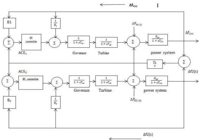
II. CONFIGURATION OF TWO-AREA POWER SYSTEM
In this configuration, area 1 & area 2 having generators G1 & G2 with different loads are interconnected with
each other via a tie-line. In this we must have to control the frequency deviation & tie-line power interchange
Fig. 1 Configuration of An Uncontrolled Two-Area Power System
III. PLANT MODEL DESCRIPTION
In this paper, two-area power system is considered as a test system, which consists of reheat turbine type
thermal station in each area. The system model under consideration is shown in Fig. 2. The LFC has two control
loops. The primary control loop is used to control the frequency by using self-regulating feature of the governor.
But, frequency error is not completely eliminated & the supplementary control loop is used to eliminate the
frequency error completely with the help of conventional integral control action. The main aim of the
supplementary control loop is to restore balance between each control area load & generation after a load
disturbanceso that the system frequency & the tie-line power flows are maintained at their nominal values.Thus,
in this paper main task is to minimize the system frequency deviation
f
1
in area 1,
f
2
in area 2 & deviationin the tie-line power flow
P
tie between the two areas under the load disturbances
Pd
1
&
Pd
2
in the twoareas. This can be achieving by using integral control action.
IV. LINEARIZED MODEL OF THE PLANT
5.1 Basic Generator Control Loops
In a two area power system, LFC is installed for each generator. The schematic diagram of frequency control
loop is shown in fig. 3. The controllers are set at a particular operating condition & take care of small changes in
load in order to maintain the frequency within the scheduled value [12].If real power changes then rotor
angle
changes,& thus the frequency f will also change. Change in angle
is due to the momentary change ingenerator speed. Thus, LFC is a non-interactive for small changes then it can be modeled & analyzed
independently.
Fig 3 Schematic Diagram of LFCof A Generator
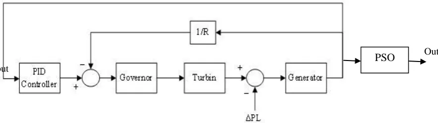
4.2 Load Frequency Control (LFC)
The main objective of LFC is to maintain real power flow in the system through control of system frequency.
Thus we can say LFC is used to maintain the frequency, to divide the load between generators & to control the
tie-line power interchange schedules. A power system consists of a governor, a turbine & a generator with
feedback of regulation constant (R). In Power system, uncontrolled load change occurs to the input of the
generator. Simple block diagram of a power system with the PID controller & PSO is shown in Fig. 4.
Out
put
Fig. 4 A Power System with the PIDController & PSO
4.3 Design of Evolutionary Controller
Evolutionary Computation (EC) is developed from the principle of the ’survival of the fitness’ proposed by
Charles Darwin in 1859. An EC technique is used to search the optimal solutions to a problem. In this
algorithm, a number of possible solutions are available for particular problem& the task is to find the best
solution from the search space.The PID controllers are simple in operation, easy in design, inexpensive
maintenance, low cost, &effectiveness for most linear system. The main disadvantage of PID controllers that,
they do not work properly for nonlinear systems, higher order & time-delayed linear systems, & particularly
complex & vague systems that have no precise mathematical model [13, 14]. Hence, an evolutionary PSO-PID
controller is used in this paper to control the voltage & frequency for different load conditions & regulation. In
this research work, PSO-PID controller is designed & implemented to overcome the drawback of conventional
fixed gain controllers.
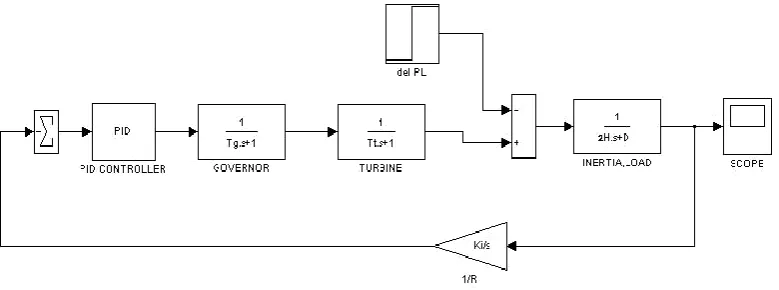
Fig 5 Simulink Model of LFC with PID Controller
4.4 Proportional Integral Derivative (PID) Controllers
PID controllers have widely been used in process control. Because of simple designing of PID controller, they
can easily control various large industrial processes. The PID controllers are used to control the dynamic
response & eliminate the steady-state error. The proportional term reduces the error response to disturbances.
The integral term shows that a pole is added at the origin which results in increasing the system type & therefore
reducing the steady-state error. The derivative term shows that a zero is added to the open loop plant transfer
function & therefore it improve the transient responses & stability of the system. To obtain the optimum results
from this system, the gain of PID controller must be tuned in such a way that the close loop system produces
desires result. Thus, PID controller is considered as a simple, easy &robust controller. The transfer function of
well-known PID controller is given by:
K
s
s
K
K
s
G
PID
p
i
d (1)The desired result should have minimum settling time, no overshoot & zero steady state error. The parameters of
the PID controller have been designed by using PSO algorithm.
4.5 Particle Swarm Optimization (PSO)
PSO is an evolutionary computation technique based on the movement & intelligence of swarms. The PSO
algorithm is discovered by Eberhart & Kennedy in 1995,motivated by social behavior of bird flocking or fish
schooling. PSO algorithm uses both cognitive (intellectual) behavior & social cooperation (group behavior) of
the birds. The bird follows the shortest path for searching their food. PSO algorithm based on the concept of
bird’s behavior [15]. Basically PSO algorithm developed for nonlinear optimization problems with continuous
location (pbest) while checking the fitness value of its current position. The fitness value of a position can be
obtained by evaluating the fitness function at the location, if a particles current location has a better fitness value
than that of its current P best ,then the P best is replace by the current location [16-17].
Each particle in the swarm has knowledge of the location with best fitness value of the entire swarm which is
called the global best (gbest). At each point along their path,each particle also compare the fitness value of their
pbestto that of gbest . If any particle has a pbest with better fitness value than that of current gbest , then the current
gbest is replace by that of ppest . The movement of particles is stopped ones all particle reached sufficiently closed
to the position with best fitness value of the swarm.
The basic features of PSO includes, it is simple in design, very fast, it can be coded in few lines,it has a memory
by which each particle remembers its best solution (global best), the initial population of the PSO is maintained
thus, there is no need for applying operators to the population, &it is easy to implement& there is no need of
gradient information.
4.6 Implementation of PSO-PID Controller
In this paper, a PSO-PID controller is used for searching the optimal parameters of LFC. In PSO algorithm, each
particle in the swarm represents a solution to the problem & it can be defined with the help of its position &
velocity [18-19].Let us consider D-dimensional search space, the position of the ith particle can be represented
by a D-dimensional vector, Xi=(Xi1,……,Xid,……..,XiD). The velocity of the particle Vi can be represented by
another D-dimensional vector Vi= (Vi1,….,Vid,….., ViD). The best position visited by the ith particle is represented
by Pi=(Pi1,…., Pid,….., PiD), & Pg asthe index of the particle visited the best position in the swarm, then Pg becomes
the best solution found so far, & the velocity of the particle & its new position will be determined according to
the following equations.
id id
gd id
id
id
WV
1
R
P
X
C2
R
P
X
V
C
………. (2)
id id
id
X
V
X
(3)C1 & C2 are the cognitive & social coefficients. R is the random number generated between 0 & 1.W is the
inertia weight that increases the overall performance of PSO. If W is larger, then it can favor higher ability for
global search while if W is lower, it favor a higher ability for local search. In order to achieve a higher
performance, W should be lower over the generations to favor global search in initial generations & local search
in the later generations. The W can be linearly decreased by using this equation.
iter
X
)
3
max(
Iter
W
W
W
W
max minmax
Where Wmax is the maximum value of inertia weight, Wmin is the minimum value of inertia weight, itermax is the
maximum of iteration in evolution process & iter is current value of iteration.
The designing steps for PSO- PID controller is as follows.
Initialize the algorithm parameters like number of generation,population, inertia weight & constants.
Initialize the value of the parameters KP, Ki & Kd randomly.
Calculate the fitness function of each particle in each generation.
Update the position, velocity, local best & global best in each generation.
Repeat the steps 3 to 5 until the maximum iteration reached of the best solution is found.
The objective function represents the function that measures the performance of the system.The fitness
function(objective)for PSO is defined as the integral of time multiplied by the absolute value of error (ITAE) of
the corresponding system. Therefore, it becomes an unconstraint optimization problem to find a set of decision
variables by minimizing the objective function [20].
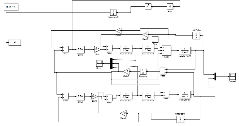
V. SIMULATION RESULTS AND ANALYSIS
The Simulation has been performed by using Mat-lab Simulink for two area power system with PSO-PID
controller. The Simu link model of a plant with PSO Algorithm based PID Controller is shown in Fig 6.System
dynamic performances, in terms of the deviations of frequencies of each area & tie-line power flows, are shown
in Fig.7. From these figures we can say that the PSO based PID controller is very effective in damping the
frequency & tie-line power oscillations & reduces the settling time, overshoot & undershoot as compared to
other controllers. The PSO algorithm is used to search an optimal parameter set containing Kp, Ki and Kd. The optimum values generated by the algorithm are stored in work space and shared with the LFC simulink model.
Fig.6 Simulink Model of A Plant With PSO Algorithm Based PID Controller
The power system simulation parameters consisting of the speed governor, turbine and generator is given in
Table 1.
Table 1. LFC Simulation Parameters
Controller
Simulation Parameters
Load Frequency Controller
Governor Tg = 0.2,
Turbine Tt = 0.5,
Load H = 10, D = 0.6,
Regulation R1= 20, R2=15
Load disturbance
∆
P
L= 0.10, 0.20
For two area LFC system, the population size is 50 & the maximum number of iterations for optimization is 50. Best value of cognitive & social coefficientsC1 & C2 are taken as 0.12 & 1.2, and W=0.9. The simulation is
realized in case of step load change.
P
L
0
.
10
,
0
.
20
p.u. MW, & the frequency change in area 1, area 2 &tie-line power change is observed.Simulation results for the two area power system are shown in Table 2. The results of optimization, give almost same results but computational time by PSO was found much less. Therefore, the proposed PSO-PID controller provides better performance than PID controller for the two area power system.
Table 2. Controller Parameters and Transient Specifications of Two Area Power System by PSO-PID Method
VI. CONCLUSION
In this research, a Particle swarm optimization tuned proportional integral derivative controller has been examined for load frequency control of two area power system. The simulink model for two area power system
with PSO-PID controller is developed in MATLAB as in fig 6. The proposed PSO-PID controller used in this
work provides a suitable stability between frequency overshoot and transient oscillations with zero steady state
error. The simulation result shown that ,the evolutionary algorithm gives much better transient response than
that of conventional PI controller &PSO works with much better efficiency as computational time minimizes,
simple and has stable convergence characteristics. The work can be extended in future either by including
non-linear parameters to the system modeled or three area power system operations will be investigated in next time
in order to improve the performance characteristics.
KP Ki Kd ts MP
PSO-PID
Controller
Area-
1
0.094
0.61
0.49
10.2
0.03
Area-
2
REFERENCES
[1] H.D. Mathur and S.Ghosh,”A comprehensive analysis of Intelligent control for load frequency
control”,IEEE Power India Conference, 2006.
[2] D.M.Vinod Kumar, “Intelligent controllers for Automatic Generation Control”, Proc. of IEEE region
10nInternational conference on global connectivity in Energy,Computer, Communication & Control,
1998,pp 557-574.
[3] P. Kundar, “Power System Stability and Control”, Tata Mcgraw Hill, Newyork, 1994.
[4] M.S. Anower et al., “Fuzzy Frequency Controller For an AGC for the improvement of power system
dynamics”, Proc. of 4th
InternationalConference on Electrical & Computer Engineering, 2006.
[5] A. Kumar, O.P. Malik, G.S. Hope, Variable structure-system control applied to AGC of anointer
connected power system, IEE Proceedings,Vol. 132, Pt. C, No. 1, pp. 23-29, January 1985.
[6] Unbehauen, H, Keuchel, U, Kocaarslan, I., Real-Time Adaptive Control of Electrical Power and Enthalpy
for a 750 MW Once-Through Boiler, Proceedings of IEE International Control Conference 91, Edinburg,
Scotland, Vol. 1, pp. 42-47, 25-28 March 1991.
[7] K.J. Astrom, T. Hagglund, The future of PIDcontrol, Control Eng. Pract.9(11)(2001)1163– 1175.
[8] Ziegler, G. and Nichols, N. B, 1942.Optimum settings for automatic controllers, Trans. ASME,
64,759-768.
[9] G.H Cohen and G.A Coon: Theoretical Consideration of Retarded Control, Trans ASME
75,pp.827/834,(1953).
[10] M.A. Panduro et al, “A comparision of Genetic algorithm, Particle Swarm Optimization and the
Differential Evolution methods for the design of Scannable circular antenna arrays”, Progress
inElectromagnetic Research, Vol.No.13, pp171-186, 2009.
[11] Haluk GOZDE et al, PSO based Load Frequency Control in a single area power system, University of
Pitesti, Scientific Bulletin, Vol.2, No.8, 2008, pp106-110.
[12] Hadi saadat, Eds 1999. “Power System Analysis”, McGraw-Hill International edition, 2005.
[13] Karnavas, K.L. and Papadopoulos, D.P, “AGC for autonomous power system using combined intelligent