ON TITANIUM ALLOY USING COPPER IMPREGNATED GRAPHITE ELECTRODE
MOHD HALIMUDIN BIN MOHD ISA @ HAMID
A thesis submitted in fulfillment of the requirements for the award of the degree of
Master of Engineering (Mechanical - Advance Manufacturing Technology)
Faculty of Mechanical Engineering Universiti Teknologi Malaysia
First of all, all the praises and thanks be to Allah S.W.T for His Love, This thesis is dedicated to my family,
To my beloved parent,
Maimunah Hj Abdullah, My supportive wife,
Amizah Abdul
My wonderful brothers and sisters,
Hamnah Mohd Isa, Mohd Helmi Mohd Isa, Huda Mohd Isa Norhana Mohd Isa
And last but not least to all my relatives and my close friends Thank you very much for your unstinting help and encouragement
May Allah bless all people that I love and it’s my honor to share this happiness with my love ones.
ACKNOWLEDGEMENTS
I would like to thank Allah Almighty for blessing me and giving me strength to accomplish this thesis. A special thanks and deep gratitude to my supervisor, Professor Dr. Safian Sharif who greatly helped in guiding and assisting me in every way throughout this entire project.
Many thank to all of the technicians and staff from KKTM Balik Pulau especially Mr Faiezem Ibrahim, Mr Asmar Suid, Mr. Ridwan Ramli, person in charge in Metrology Laboratory, Mr. Ashamudin Technician in Material Failure Testing and Mr. Mohzani lecturer from Department of Mechanical Engineering, USM and other technical staff for their cooperation and assistance me in the various laboratory tasks.
ABSTRACT
Electrical discharge machining (EDM) which is very prominent amongst the non conventional machining methods is expected to be used quite extensively in machining titanium alloys due to the favorable features and advantages that it offers. This thesis presents the EDMing of titanium alloy (Ti-6246) using copper impregnanted graphite electrode with diameter of 8 mm. The main purpose of this study was to investigate the influenced of various parameters involved in EDM on the machining characteristics, namely, material removal rate (MRR), electrode wear ratio (EWR), surface roughness (Ra) and overcut.
In this investigation, the machining trials were performed using a Sodick linear motor EDM sinker series AM3LThe experimental plan for the processes were conducted according to the design of experimental (DOE) and the results were statistically evaluated using analysis of variance (ANOVA). Results showed that current was the most significant parameter that influenced the machining responses on EDM of Ti-6246.
ABSTRAK
Proses pemesinan nyahcas elektrik (EDM) yang agak dominan di antara proses pemesinan bukan konvensional dijangkakan akan bertambah meluas penggunaannya disebabkan sifat-sifat dan kelebihan yang dihasilkan keatas bendakerja. Kajian yang dijalankan ini adalah mengenai pemesinan EDM sinker terhadap bahan aloi titanium (Ti-6246) dengan menggunakan copper impregnanted graphites yang berdiameter 8 mm sebagai elektrod. Tujuan utama kajian ini adalah untuk mengkaji kesan beberapa parameter yang terlibat dalam EDM proses terhadap kriteria pemesinan seperti kadar pembuangan bahan (MRR), nisbah kehausan elektrod (EWR), kekasaran permukaan (Ra) dan ‘overcut’.
Dalam kajian ini, pemesinan yang dijalankan ke atas titanium dilakukan menggunakan Sodick linear motor EDM series AM3L. Ujian pemesinan untuk kedua-dua proses telah dinilai secara statistik menggunakan analisa variasi (ANOVA). Keputusan menunjukkan arus lektrik merupakan parameter yang paling signifikan yang mempengaruhi tindak balas pemesinan EDM ke atas Ti-6246.
CONTENTS
CHAPTER TITLE PAGE
DECLARATION ii
ACKNOWLEDGEMENT iv
ABSTRACT v
ABSTRAK vi
CONTENTS vii
LIST OF TABLES x
LIST OF FIGURES xii
NOMENCLATURE xiv
LIST OF APPENDICES xv
1 INTRODUCTION
1.1 Overview 1
1.2 Background of Research 2
1.3 Statement of the research problem 4
1.4 Research Question 4
1.5 Objectives 4
1.6 Scope of study 5
2 LITERATURE REVIEW
2.1 Introduction 6
2.2 Electric Discharge Machining (EDM) 7
2.2.1 Principle EDM Spark Erosion 8
2.2.3.4 Surface Roughness (SR) 12
2.2.3.5 Machinability 12
2.2.3.6 Material Cost 13
2.2.3.7Graphite Electrode 13
2.2.4 Flushing 14
2.2.5 Dielectric Fluid 17
2.3 Machining Characteristics 17
2.3.1 Material Removal Rate 17
2.3.2 Electrode Wear Rate, EWR 18
2.3.3 Surface Roughness, SR 19
2.4 Titanium Alloys and Their Machinability 20
2.4.1 Introduction 20
2.4.2 Classification of Titanium Alloys 22
2.4.2.1 Commercially pure (CP) titanium (unalloyed) 23
2.4.2.2 Alpha and near-alpha alloys 23
2.4.2.3 Alpha-beta Alloys 24
2.4.2.4 Beta alloys 24
2.4.3 EDM of Titanium Alloys 25
2.4.3.1 Machining Titanium Alloys with EDM 25
2.5 Design of Experiment (DOE) 26
2.5.1 Two-level Fractional Factorial Design 27
2.5.2 Response Surface Methodology (RSM) 28
2.5.3 Test of Statistical Significance 28
3 RESEARCH DESIGN
3.1 Introduction 30
3.2 Research Design Variables 30
3.2.1 Response Parameters 31
3.2.2 Machining Parameters 31
3.2.4 Electrode Material 33
3.2.5 Machine and Equipment 34
3.3 Analysis 39
3.3.1 Statistical Analysis 39
3.3.2 Metal Removal Rate (MRR) Measurement 40 3.3.3 Electrode Wear Rate (EWR) Measurement 41
3.3.4 Surface Roughness Measurement 42
3.3.5 Measurement of Hole Diameter 42
3.3.6 Experimental Design 43
4 RESULT AND ANALYSIS
4.1 Introduction 46
4.2 Experimental Results 47
4.3 Result Analysis 48
4.3.1 Analysis Results for Material Removal Rate, MRR 49 4.3.2 Analysis Results for Electrode Wear Rate, EWR 56 4.3.3 Analysis Results for Surface Roughness, SR 61
4.3.4 Analysis Results for Overcut 64
4.3.5 Analysis with Central Composite design 70
5 DISCUSSION
5.1 Introduction 86
5.2 Material removal rate, MRR 87
5.3 Electrode wear rate EWR 87
5.4 Surface roughness, SR 88
5.5 Overcut 89
5.6 White layer 89
6 CONCLUSIONS
6.1 Introduction 91
6.2 Conclusion 91
REFERENCES 93
LIST OF TABLES
TABLE TITLE PAGE
2.1 Physical and mechanical properties of elemental titanium 21 2.2 Some commercial and semicommercial grades and alloy titanium 22
3.1 Machining parameters 31
3.2 The composition of Ti-6246 32
3.3 Mechanical Properties of Ti-6246 33
3.4 Typical Value for copper impregnanted graphite 34
3.5 Factor and level for EDM of Ti-6246 43
3.6 Two level full Factorial experiment with four factor and four center point 44
3.7 Experimental plan for EDM of Ti-6246 45
4.1 Experimental results for EDM of Ti-6246 47
4.2 ANOVA table for MRR in EDM process 51
4.3 ANOVA table for EWR in EDM process 57
4.4 ANOVA table for SR in EDM process 61
4.5 ANOVA table for Overcut in EDM process 65
4.6 Summary of significant factors in EDM experiments 70
4.7 Experimental plan for EDM of Ti-6246 (CCD) 71
4.8 Response results for EDM of Ti-6246 (CCD) 72
4.9 ANOVA table for response surface quadratic model for MRR in 73 EDM of Ti-6246
4.10 ANOVA table after transformation for MRR in EDM of Ti-6246 74
4.11 Final ANOVA for EWR in EDM of Ti-6246 77
4.12 Final ANOVA for SR in EDM of Ti-6246 79
LIST OF FIGURES
FIGURE TITLE PAGE
2.1 Classification of EDM processes 7
2.2 Types of EDM processes 8
2.3 Spark gap 8
2.4 Phase of electrical discharges 9
2.5 Ignition of the first discharge 15
2.6 The particles created 16
2.7 The additional particle density 16
3.1 Sodick AM3L 35
3.2 Mitutoyo Formtracer CS-5000 surface roughness tester 35
3.3 Zeiss – Coordinate Measuring Machine (CMM) 36
3.4 Precisa Balance 36
3.5 Buehler automatic mounting machine 37
3.6 Grinder and Polisher 38
3.7 Optical microscope 38
3.8 Flowchart outlining the analysis steps undertaken 40 4.1 Pareto Chart for significant effect choosed (MRR) 49 4.2 Normal probability plots of residuals for MRR in EDM process 52 4.3 Residual vs predicted response for MRR in EDM process 52 4.4 Residual vs run number response for MRR in EDM process 53 4.5 Interaction between Peak Current (A) and Pulse on time (C) 54 4.6 Interaction between Peak Current (A) and Pulse on time (D) 54 4.7 Interaction between Pulse on time (C) and Pulse off time (D) 55
4.9 Normal probability plots of residuals for EWR in EDM process 58 4.10 Residual vs predicted response for EWR in EDM process 58 4.11 Residual vs run number response for EWR in EDM process 59 4.12 Interaction between Peak Current (A) and Servo Voltage (B) 60 4.13 Interaction between Peak Current (A) and Pulse Off Time (D) 60 4.14 Normal probability plots of residuals for SR in EDM process 62 4.15 Residual vs predicted response for SR in EDM process 63 4.16 Residual vs run number response for SR in EDM process 63 4.17 Interaction between Peak Current (A) and Pulse On Time (C) 64 4.18 Normal probability plots of residuals for overcut in EDM process 66 4.19 Residual vs predicted response for overcut in EDM process 67 4.20 Residual vs run number response for Overcut in EDM process 67 4.21 Interaction between Peak Current (A) and Pulse On Time (C) 68 4.22 Interaction between Peak Current (A) and Pulse On Time (D) 69 4.23 Interaction between and Pulse On Time (C) and Pulse Off Time (D) 69 4.24 Normal probability plots of residuals for MRR in EDM process (CCD) 75 4.25 Residual vs predicted response for EWR in EDM process (CCD) 76 4.26 3D response surface for MRR in EDM process (CD) interaction 76 4.27 3D response surface for MRR in EDM process (AD) interaction 77
4.28 One factor plot for EWR in PMD-EDM process 78
4.29 One factor plot for Overcut in PMD-EDM process 80 4.30 Pulse off time (D) plot for Overcut in PMD-EDM process 80 4.31 3D response surface for Overcut in EDM process (CD) interaction 82 4.32 3D response surface for Overcut in EDM process (AD) interaction 82
5.1 White layer with lower pulse on current 90
LIST OF ABBREVIATIONS AND SYMBOLS
ANOVA - Analysis of variance CCD - Central composite design CMM - Coordinate measuring machine EDM - Electro discharge machining EWR - Electrode wear rate
EWW - Weight of electrode used MRR - Material/metal removal rate RSM - Response surface methodology
SR - Surface Roughness
Tm - Machining times
Wa - Weight of workpiece after machining Wb - Weight of workpiece before machining WRW - Weight of workpiece used
x1,x2, x3,…,xk - Input variables
α - Alpha phase
LIST OF APPENDICES
APPENDIX TITLE PAGE
A-1 Workpiece preparation plan 97
A-2 Actual workpiece preparation 97 A-3 Electrode preparation 98 A-4 Electrode and Workpiece for experiment 98 B-1 Program For hole makking on EDM die sinking (AM3L) 99 C-1 Experimental results for EDM of Ti-6246 (two level full factorial) 100
C-2 Experimental results for EDM of Ti-6246 (CCD) 101
D-1 Unmodified ANOVA table for MRR in EDM process 102
D-2 Box Cox Plot for MRR in EDM process 103
E-1 Ra reading for sample run 18 104
F-1 White layer for low and high MRR 105
F-1 White layer for low and high Ra 105
F-1 White layer for low and high Overcut 106
CHAPTER 1
INTRODUCTION
1.1 Overview
The use of light, thin and compact mechanical elements has recently become a global trend. The search for new, lightweight material with greater strength and toughness has led to the development of new generation of materials such as titanium and nickel alloys, although their properties may create major challenges during machining operations. Having greater hardness and reinforcement strength, these materials are difficult to machine by the traditional methods. Although these materials can be machined conventionally, sub surface damages such as metallurgical alterations, work hardening, delimitation and microcracks and others can occur under certain circumstances which cause a detrimental effect on the performance of the machined component. Since the cost of using conventional machining is generally prohibitive, non-conventional machining such as electric discharge machining (EDM) and laser machining probably amongst the ideal technique in dealing with these materials.
growing acceptance in many industries, along with the experience gained by progressive fabricators, a broad base of titanium machining knowledge is now exist. It was reported that commercially pure grades of titanium [ASTM B, Grades 1, 2, 3, 4] (ASM International, 1988) can be machined much easier than aircraft alloys.
Although titanium alloys is tough it can experienced sub-surface damaged during machining operations. Damage appears in the form of microcracks, built up edge, plastic deformation, heat affected zones and tensile residual stresses (Sharif, 1999; and Hong et al., 2001). In service, these can lead to degraded fatigue strength and stress concentration.
Non-traditional machining of metal removal such as EDM expected to be used extensively years to come, because it’s favorable results. It is particularly useful for rapid removal of metal of free form surface or complex shaped parts, thin sections, and from large areas down to shallow depths. This process has less damaging effect on the mechanical properties of the metal (Rival, 2005).
1.2 Background of Research
EDM is a non-traditional concept of machining which has been widely used to produce dies and molds. It is also used for finishing parts for aerospace and automotive industry and surgical components. This technique has been developed in the late 1940s (Norliana Mohd Abbas et al., 2006).where the process is based on removing material from a part by means of a series of repeated electrical discharges between tool called the electrode and the work piece in the presence of a dielectric fluid (Norliana Mohd Abbas et al., 2006).
Optimum selection of process parameters is very much essential, as this is a costly process to increase production rate considerably by reducing the machining time. Several researchers carried out various investigations for improving the process performance. As EDM is a very complex and stochastic process, it is very difficult to determine optimal parameters for best machining performance, i.e., productivity and accuracy (T. A. El-Taweel, 2009). Material removal rate, tool wear, surface finish and also overcut are most important output parameters, which influence the cutting performance. But these performance parameters are conflicting in nature. The higher the MRR, the better, whereas the lower the tool wear, the better. In a single objective optimization, there exists only one solution. But in the case of multiple objectives, there may not exist one solution, which is the best with respect to all objectives. In EDM process, it is difficult to find a single optimal combination of process parameters for the performances parameters, as the process parameters influence them differently. Hence, there is a need for a multi-objective optimization method to arrive at the solutions to this problem.
1.3 Statement of the research problem
How does a new developed electrode performed when EDM alpha beta titanium alloy Ti-6246 with respect to material removal, electrode wear, dimensional hole accuracy and surface finish.
1.4 Research Question
a. What are the machining parameters that influence the EDMing of Ti-6246 using copper impregnanted graphite electrode.
b. What are the significant parameters that influence to the responce during EDM of Ti-6246.
c. What correlations exist among the parameters and machining responses and also how to quantify.
d. What mathematical model is suitable to represent the performance evaluation of EDMing Ti-6246.
1.5 Objectives
The objectives of the study are:
1.6 Scope of study
a) Machining responses to be investigated are material removal rate (MRR), electrode wear rate (EWR), surface roughness (SR) and overcut.
b) Electro-Discharge Machining (Die sinking) AM3L SODICK will be employed.
c) Alpha-beta alloy, Ti 6Al 2Sn 4Zr 6Mo (Ti-6246) will be selected as workpiece material.
SOFTWARE DEVELOPMENT OF CONCURRENT DESIGN
FOR MANUFACTURING PROCESS SELECTION
OF PLASTIC MATERIALS
MOHD YUSRI BIN MOHD YUNUS
A project report submitted in partial fulfilment of the
requirements for the award of the degree of
Master of Engineering (Mechanical – Advanced Manufacturing Technology)
Faculty of Mechanical Engineering
Universiti Teknologi Malaysia
To my beloved family Mohd Yunus Bin Ibrahim, Selamah Binti Hasan and my wife
ACKNOWLEDGEMENT
Alhamdullilah, thank to Allah, because of Him we are still here, breathing
His air, pleasuring His entire gift in this world. And most of all, for giving me
opportunities to learn His knowledge.
This work was supervised by Dr. Ariffin B. Abdul Razak from Universiti
Teknologi Malaysia. I greatly appreciate all his helps and guidances.
I am indebted to my parents, Mohd Yunus B. Ibrahim and Selamah Bt. Hasan
and my wife Noor Jihan Bt. Harun, without whose help, encouragement and patience
I would never have gotten this thesis completed and who made it all worthwhile.
Thanks to all classmates on your sincere and solid support also to management part
of Kolej Kemahiran Tinggi MARA Balik Pulau.
Finally, thank you to all the other people who have supported me during the
For plastic products, one of the most critical decisions made during the early
design stage is the selection of an appropriate manufacturing process. Designers or
engineers must concurrently select the suitable plastic materials and its processing
method while they develop the part geometry. It is thus meaningful to develop such a
system for helping the engineers at preliminary design stages. This project proposes
a system of selecting suitable manufacturing processes and materials in concurrent
design for manufacturing environment. The prototype system called PROSEP, use
Boothroyd-Dewhurst DFM methodology in evaluating and selecting suitable
manufacturing process/material. Visual Basic computer programming language is
used as a tool for system development. Three major factors are considered; shape
attributes of part, material requirements and production characteristics. The working
of the prototype system is demonstrated using prismatic and rotational parts case
ABSTRAK
Untuk produk plastik, satu daripada keputusan paling kritikal dibuat semasa
permulaan peringkat reka bentuk adalah pemilihan satu proses pembuatan yang
sesuai. Para jurutera mesti serentak memilih bahan-bahan plastik yang sesuai dan
cara pembuatannya manakala mereka membangunkan bahagian geometri. Oleh itu
adalah amat bermakna bagi membangunkan satu sistem yang boleh membantu
jurutera-jurutera pada permulaan fasa reka bentuk. Projek ini mencadangkan satu
sistem untuk memilih proses-proses pembuatan dan bahan-bahan yang bersesuaian
dalam reka bentuk serentak untuk bidang pembuatan. Sistem yang dinamakan
PROSEP, menggunakan kaedah Boothroyd-Dewhurst DFM dalam menilai dan
memilih proses pembuatan atau bahan yang munasabah. Bahasa pengaturcaraan
Visual Basic digunakan untuk pembangunan sistem. Tiga faktor utama diambil kira;
sifat-sifat bentuk bahagian, syarat-syarat bahan dan ciri-ciri pengeluaran.
Penggunaan sistem prototaip ini ditunjukkan menggunakan kajian kes komponen
CHAPTER TITLE PAGE
DECLARATION ii
DEDICATION iii
ACKNOWLEDGEMENTS iv
ABSTRACT v
ABSTRAK vi
TABLE OF CONTENTS vii
LIST OF TABLES xi
LIST OF FIGURES xii
LIST OF APPENDICES xiv
1 INTRODUCTION
1.1 Introduction to the Problem 1
1.2 Objective of Study 3
1.3 Scopes of Study 4
1.4 Methodology of Study 4
1.5 Significant of Study 6
1.6 Thesis Stucture 6
2 LITERATURE REVIEW ON MANUFACTURING
PROCESSES AND PLASTIC MATERIALS
2.1 Introduction 8
2.2 Design for Manufacturingand Assembly 8
2.3 Manufacturing Processes for Plastic Materials 10
2.3.1 Injection Moulding 10
2.3.1.1 Process Capabilities 12
2.3.2 Blow Moulding 14
2.3.2.1 Extrusion Blow Moulding 14
2.3.2.2 Injection Blow Moulding 15
2.3.2.3 Process Capabilities 16
2.3.3 Structural Foam Moulding 18
2.3.3.1 Process Capabilities 19
2.3.4 Rotational Moulding 21
2.3.4.1 Process Capabilities 22
2.3.5 Thermoforming 25
2.3.5.1 Process Capabilities 26
2.3.6 Machining 28
2.3.6.1 Process Capabilities 31
2.4 Plastic Materials 32
2.4.1 Thermoplastics 33
2.4.2 Thermosets 34
2.4.3 Elastomers 35
2.5 Review on Previous Studies 37
2.6 Summary 41
3 BOOTHROYD-DEWHURST DFM METHODOLOGY
3.1 Introduction 42
3.2 Overview on Boothroyd-Dewhurst
DFM Methodology 42
3.3 Selection of Manufacturing Processes 44
3.4 Selection of Materials 48
4 TOOL FOR PROTOTYPE SOFTWARE
DEVELOPMENT
4.1 Introduction 57
4.2 Overview on Visual Basic Software 57
4.3 Object-Oriented Programming 60
4.4 Interface in Visual Basic 62
4.5 Database in Visual Basic 62
4.6 Summary 65
5 DEVELOPMENT OF PROTOTYPE SOFTWARE
5.1 Introduction 66
5.2 Prototype Software Development 67
5.3 Implementation of Prototype Software 69
5.4 Structure of Prototype Software 72
5.5 Graphical User Interface of Prototype Software 72
5.5.1 Welcome Window Interface 73
5.5.2 Main Window Interface 74
5.5.3 Design Guides Window Interface 75
5.5.4 Result WindowInterface 77
5.5.5 Help Window Interface 78
6 VERIFICATION OF PROTOTYPE SOFTWARE
6.1 Introduction 80
6.2 Case Studies 80
6.2.1 Prismatic Part 81
6.2.2 Rotational Part 84
6.3 Prototype Software Capabilities 88
6.4 Summary 89
7 DISCUSSIONS
7.1 Introduction 90
7.2 Discussion on Prismatic Part Case Study 90
7.3 Discussion on Rotational Part Case Study 93
7.4 Summary 95
8 CONCLUSIONS
8.1 Introduction 96
8.2 Future Work Recommendations 96
8.3 Concluding Remark 97
REFERENCES 98
TABLE NO. TITLE PAGE
2.1 Process capabilities of injection moulding 13
2.2 Process capabilities of blow moulding 17
2.3 Process capabilities of structural foam moulding 20
2.4 Process capabilities of rotational moulding 24
2.5 Process capabilities of thermoforming 28
2.6 Process capabilities of machining 32
2.7 Previous studies on manufacturing and process
selection approach 40
3.1 A compatibility matrix between processes and materials 46
3.2 Process capabilities of some selected processes 47
4.1 Example of database table 63
5.1 Example to calculate Total Rating Score 71
5.2 Example to rank the possible materials 71
6.1 Design requirements for main base of paper trimmer 82
6.2 Design requirements for traffic cone 86
7.1 Possibilities of processes and materials for main base
of paper trimmer 91
LIST OF FIGURES
FIGURE NO. TITLE PAGE
1.1 Typical plastic products 2
1.2 Flowchart represents the methodology of study 5
2.1 Relationship between DFA and DFM with selection of
materials and processes 9
2.2 Injection mouldingprocess 11
2.3 Schematic diagram of the extrusion blow moulding process 15
2.4 Structural foam product 18
2.5 Rotational moulding process 22
2.6 Straight vacuum forming 25
2.7 Elastomers bridge the hardness ranges of rubbers and plastics 36
3.1 Flowchart of Boothroyd–Dewhurst DFM methodology 43
3.2 (a) Depressions in a single direction 51
(b) Depressions in more than one direction 51
3.3 (a) Uniform cross section 51
(b) Non-uniform cross section 51
3.4 (a) Part that can be generated by rotation of a single axis 52
(b) Part that cannot be generated by rotation of a single axis 52
4.1 Start-up of Visual Basic software 59
4.2 Relationship of Visual Basic application and database 64
5.1 Software development flowchart 68
5.2 Flowchart of PROSEP Software 70
5.3 Prototype software structure 72
5.4 Welcome Window of PROSEP software 73
6.1 Example of prismatic part to evaluate by using prototype
software 81
6.2 Input format of main base part by using PROSEP software 83
6.3 Result Window for main base of paper trimmer 84
6.4 Example of rotational part to evaluate by using prototype
software 85
6.5 Input format of traffic cone by using PROSEP software 87
LIST OF APPENDICES
APPENDIX TITLE PAGE
A Project planning 101
-Gantt chart of Semester 1 -Gantt chart of Semester 2 B Comparative costs and production characteristics for processing of plastics 102
C Comparison of some thermoplastics properties 103
D Comparatives of properties of some thermosets 105
E Comparison of some elastomers properties 106
F Shape generation capabilities of processes 107
G Visual Basic source code of PROSEP software 108
H Database of plastic processes characteristics 134
INTRODUCTION
1.1 Introduction to the Problem
Plastic materials have become an essential necessity in all aspect of today’s
recent life. Plastics are replacing most of the materials today due to good mechanical,
chemical and thermal properties. Plastics are found on various products ranging from
housing appliances, telecommunication equipment, electronics product, clothing and
commercial market. One of the reasons for the great popularity of plastics in a wide
variety of industrial applications is the great range of properties exhibited by plastics and
their ease of processing (Harper, 2006).
Plastic properties can be modified to meet particular needs by changing the
atomic composition of the repeat structure, by changing molecular weight and molecular
weight distribution. The flexibility can also be varied through the existence of side chain
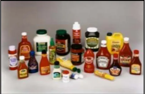
branching, via the lengths and polarities of the side chains. Figure 1.1 shows the
Figure 1.1: Typical plastic products
The importance of process and materials selection in designing plastic products
has increased in recent years. The adoption of concurrent design methods and Design for
Manufacturing has brought design engineers into the design process at an earlier stage.
The selection of plastics material and an appropriate manufacturing process for a
specific application is always a challenging task. Wrong process and material selection
lead to product failure. In this situation, one of the most important tasks for engineers or
designers is process and material selection at the early stages.
Some plastic processes can readily produce certain classes of shape attributes,
but it may be very costly, or even impractical, to realize other classes of shape attributes.
Furthermore, some processes may be totally unsuited with certain materials. As a result,
together with the selection of materials, process selection becomes a very important
decision before designers continue to the design of detailed geometry.
As a design engineers, they requires general knowledge of the part design,
process limitations, advantages and disadvantages, success and failure affect with a
the part.
By tradition, the decision to choose an appropriate manufacturing process is
delegated to an expert who employs a complex reasoning process based on empirical
knowledge and previous experience. This selection procedure may result in inconsistent
or poor choices if the decision is made by a novice who fails to map correctly the
product characteristics with the manufacturing efficiency of various manufacturing
processes (Raviwongse et al., 2000).
In order to select the most suitable material and process, a lot of methods and
techniques has developed, but only a few work has been done in developing a
computer-aided software that accommodates information about different plastics processes,
evaluates the appropriateness of each process with the design engineer’s needs, and
assist in selecting the most appropriate process. As a result this project has tried to
contribute on this issue to help an engineer at the early design stage.
1.2 Objective of Study
The main objective of this project is to develop the prototype system for
concurrently selecting the plastic materials and its processing method while attributes of
1.3 Scopes of Study
The scope of work is clearly defined the specific field of the research and ensure
that the entire content of this project is confined the scope. Scopes of this project are
limited to:
i. Concentrate on plastic materials in term of process selection of material
properties for thermoplastics, thermosets and elastomers.
ii. Use Boothroyd-Dewhurst DFM methodology to do the process selection.
iii. Use Visual Basic computer programming language for system development.
1.4 Methodology of Study
The methodology of study begins with literature review on existing materials
selection and manufacturing processes procedures. The next step is review on
manufacturing processes capabilities and plastic material properties. At this stage all the
advantages, disadvantages and limitations of processes and materials are analysed. The
analysis or selection of processes and materials are done using Boothroyd-Dewhurst
DFM methodology.
Visual Basic computer programming software is used as a tool for prototype
system development. This stage is the critical part of the study that involved with
develops the graphical user interface and writes the program coding. Finally, the
verification of the prototype software will be done by doing the case studies of prismatic
Figure 1.2: Flowchart represents the methodology of study Review on existing material s selection and
manufacturing process
Review on plastic materials in term of process selection of material properties for thermoplastics, thermosets and elastomers.
Methodology: Use Boothroyd-Dewhurst DFM methodology to do the process
selection
Tool: Use Visual Basic computer programming language for system
development
Verification: Case studies on prismatic rotational parts
Result satisfied?
Recheck system programming
1.5 Significant of Study
The use of prototype software, PROSEP (Process Selection of Plastic Materials)
should help the designers or engineers to select a manufacturing process for engineering
plastics effectively. On the other hand, this prototype software can also be used as a
teaching tool or as guidance to the inexperienced designer or student in manufacturing
processes and plastic materials selection. The design of a part is often iterative in
environment, but by using PROSEP software, major design drivers can be identified
early in the design stages, and improvement can be simply and economically made.
1.6 Thesis Structure
The thesis presents the software development for concurrent design for
manufacturing process selection of plastic materials. This thesis consists eight chapters.
In first chapter, it discusses generally an introduction to the problem, objective, scopes
and significant of this project as long as summary of works.
Chapter 2 focuses on the literature review, which introduces the overview on
Design for Manufacturingand Assembly. Then the detail discussion and explanation on
manufacturing process capabilities for plastic materials are covered. The discussion
covers six processes namely injection moulding, blow moulding, structural foam
moulding, rotational moulding, thermoforming and machining. Besides, the types of
plastic materials; thermoplastics, thermosets and elastomers and related properties also
discussed in details. This chapter is then described by related researches on existing
software. It discusses about Visual Basic software. In Chapter 5, it provides the
methodology that is used through out the work of this project. It covers the software
development methodology in terms of prototype software structure and graphical user
interface.
Chapter 6 will focuses on verification of prototype software. The case studies on
prismatic and rotational parts will discuss on this chapter. On the other hand, the
software capabilities also are explained. The result of case studies and discussions on
that result will be presented in Chapter 7. Last but not least, Chapter 8 presents the
conclusions of the project as well as some constructive suggestions for further
development of this project. The project outcomes are concluded in this chapter.
1.7 Summary
In this chapter, the background of the project, objective, scopes, methodology of
study and significant of study were discussed. The structure of the thesis also was