555-233-109
Comcode 108671397
Issue Issue 2
Preventing Toll Fraud
Toll Fraud is the unauthorized use of your telecommunications system by an unauthorized party (for example, a person who is not a corporate employee, agent, subcontractor, or working on your company’s behalf). Be aware that there is a risk of toll fraud associated with your system and that, if toll fraud occurs, it can result in substantial additional charges for your telecommunications services.
Lucent Technologies Fraud Intervention
If you suspect that you are being victimized by toll fraud and you need technical assistance or support, call the Technical Service Center’s Toll Fraud Intervention Hotline at 1-800 643-2353.
Providing Telecommunications Security
Telecommunications security (of voice, data, and/or video communications) is the prevention of any type of intrusion to (that is, either unauthorized or mali-cious access to or use of your company’s telecommunications equipment) by some party.
Your company’s “telecommunications equipment” includes both this Lucent product and any other voice/data/video equipment that could be accessed via this Lucent product (that is, “networked equipment”).
An “outside party” is anyone who is not a corporate employee, agent, subcontrac-tor, or working on your company’s behalf. Whereas, a” malicious party” is any-one (including someany-one who may be otherwise authorized) who accesses your telecommunications equipment with either malicious or mischievous intent.
Such intrusions may be either to/through synchronous (time multiplexed and/or circuit-based) or asynchronous (character-, message-, or packet-based) equip-ment or interfaces for reasons of:
■ Utilization (of capabilities special to the accessed equipment) ■ Theft (such as, of intellectual property, financial assets, or toll -facility
access)
■ Eavesdropping (privacy invasions to humans)
■ Mischief (troubling, but apparently innocuous, tampering)
■ Harm such as harmful tampering, data loss or alteration, regardless of motive or intent.
Be aware that there may be a risk of unauthorized or malicious intrusions associated with your system and/or its networked equipment. Also realize that, if such an intrusion should occur, it could result in a variety of losses to your company (including but not limited to, human/data privacy, intellectual property, material assets, financial resources, labor costs, and/or legal costs).
Your Responsibility for Your Company’s Telecommunications Security The final responsibility for securing both this system and its networked equip-ment rests with you - a Lucent customer’s system administrator, your telecommu-nications peers, and your managers. Base the fulfillment of your responsibility on acquired knowledge and resources from a variety of sources including but not limited to:
■ Installation documents ■ System administration documents ■ Security documents
■ Hardware-/software-based security tools ■ Shared information between you and your peers ■ Telecommunications security experts
To prevent intrusions to your telecommunications equipment, you and your peers should carefully program and configure your:
■ Lucent provided telecommunications system and their interfaces ■ Lucent provided software applications, as well as their underlying
hardware/software platforms and interfaces
■ Any other equipment networked to your Lucent products
equipment generates, uses, and can radiate radio-frequency energy and, if not installed and used in accordance with the instructions, may cause harmful inter-ference to radio communications. Operation of this equipment in a residential area is likely to cause harmful interference, in which case the user will be required to correct the interference at his own expense.
Part 68: Network Registration Number. This equipment is registered with the FCC in accordance with Part 68 of the FCC Rules. It is identified by FCC regis-tration number AS593M-13283-MF-E. Refer to “Federal Communications Com-mission Statement” in “About This Book” for more information regarding Part 68.
Canadian Department of Communications (DOC) Interference Information
This digital apparatus does not exceed the Class A limits for radio noise emis-sions set out in the radio interference regulations of the Canadian Department of Communications.
Le Présent Appareil Nomérique n’émet pas de bruits radioélectriques dépassant les limites applicables aux appareils numériques de la class A préscrites dans le reglement sur le brouillage radioélectrique édicté par le ministére des Communi-cations du Canada.
Trademarks See “About This Book.”
Ordering Information
Call: Lucent Technologies Publications Center
Voice 1 800 457-1235International Voice 317 361-5353 Fax 1 800 457-1764International Fax 317 361-5355 Write: Lucent Technologies Publications Center
P.O. Box 4100 Crawfordsville, IN 47933 Order: Document No. 555-233-109
Comcode 108671397 Issue 2, June 2000
For additional documents, refer to the section in “About This Book” entitled “Related Documents.”
You can be placed on a standing order list for this and other documents you may need. Standing order will enable you to automatically receive updated versions of individual documents or document sets, billed to account information that you provide. For more information on standing orders, or to be put on a list to receive future issues of this document, contact the Lucent Technologies Publications Center.
European Union Declaration of Conformity
The “CE” mark affixed to the DEFINITY ONE equipment described in this book indicates that the equipment conforms to the following European Union (EU) Directives:
■ Electromagnetic Compatibility (89/336/EEC) ■ Low Voltage (73/23/EEC)
■ Telecommunications Terminal Equipment (TTE) i-CTR3 BRI and i-CTR4 PRI
For more information on standards compliance, contact your local distributor.
Comments
Contents
Contents iii
About This Book xv
■ Conventions used in this book xv
■ Related documents xvi
■ How to order documentation xvi ■ How to comment on this book xvii
■ Where to call for technical support xvii
■ Security issues xviii
■ Trademarks xviii
■ Standards compliance xix
■ Electromagnetic compatibility standards xx
■ Anti-static protection xx
■ Remove/install circuit packs xxi ■ Federal Communications Commission statement xxi
Part 68: Statement xxi
Means of Connection (U.S.) xxii
1
Install and Cable the Cabinet 1-1■ Check customer’s order 1-2
■ Correct shipping errors 1-2
■ Unpack and inspect 1-2
■ Install the system cabinet 1-6 Verify the carrier address ID 1-6
Floor-mount the cabinet 1-7
Wall-mount the cabinet 1-8
Install cabinet — wall-mount 1-9
Install left and right panels — wall-mount 1-11
■ Check AC power and ground 1-12
Check AC power 1-12
Approved grounds 1-13
Approved floor grounds 1-14
Uninterruptible power supply 1-14
Connect cabinet grounds and other grounds 1-16
Install the ground block 1-16
Install coupled bonding conductor 1-18
Connect and route the power cords 1-18
■ Cable the system 1-20
Install Processor Interface cable and TDM/LAN
bus terminators 1-20
■ Install main distribution frame
(MDF) and external modem 1-21
Install the MDF 1-21
Bottom-mounted MDF with modem 1-21
Install the external modem 1-23
■ Install equipment room hardware 1-24 Cross-connect the cabinet to the MDF 1-24
Allowable and non-allowable circuit packs 1-24
Circuit pack installation 1-29
Circuit pack slot loading 1-29
Off-premises circuit protection 1-33
Install sneak fuse panels 1-34
Label the main distribution frame 1-37
■ Set ringing option 1-38
■ Install and wire telephones and other equipment 1-40 Telephone connection examples 1-40
Connect adjunct power 1-42
Station wiring examples 1-43
Analog tie trunk example 1-45
Digital tie trunk example 1-46
Cable examples for tie trunk connectivity 1-47
DS1 tie trunks between collocated systems 1-47
3-pair and 4-pair modularity 1-49
Adjunct power connections 1-50
Auxiliary power 1-51
Install Attendant Console — optional 1-52
Hard-wire bridging 1-52
Dual wiring of 2-wire and 4-wire endpoints 1-52
■ Connect external alarms and auxiliary connections 1-53
Alarm input 1-53
Alarm output 1-53
UPS alarm connection 1-54
Emergency transfer and auxiliary power 1-55
Telephone pin designations 1-55
■ Install the BRI terminating resistor 1-56 Terminating resistor adapter 1-57
Closet mounted (110RA1-12) 1-58
■ Install multi-point adapters 1-60 BR851-B adapter (T-adapter) 1-60
367A adapter 1-61
Basic multi-point installation distances 1-62
■ Install off-premises station wiring 1-63 Install off-premises or out-of-building stations 1-63
Analog off-premises stations 1-63
Circuit protectors 1-66
Digital out-of-building telephones 1-67
■ Install emergency transfer panel and
associated telephones 1-68
Install the emergency transfer panel 1-68
Install telephone for power transfer unit 1-75
■ Connect modem to telephone network 1-76
■ Connect modem 1-77
External modem option settings 1-77
■ Set neon voltage to prevent ring ping 1-78
■ Complete installation 1-79
■ View LEDs to determine power and fan alarm state 1-79
2
Connectivity and Access to DEFINITY ONE 2-1■ Physical connections 2-2
Via a PCMCIA ethernet (NIC)
network connection 2-2
Via local
Via RAS (modem)
dial up 2-3
Create a connection icon for DEFINITY ONE 2-3
Dial up 2-5
Via customer LAN 2-11
DEFINITY LAN gateway (DLG) 2-12
■ Access methods 2-16
Via a Telnet session 2-16
Via a Web browser session 2-18
Via pcAnywhere 2-21
Start the pcAnywhere application on
DEFINITY ONE 2-21
System administration/DEFINITY site
administration (DSA) 2-26
■ DEFINITY ONE Lucent personnel logins 2-28
3
System Initialization 3-1■ Power up and observe LEDs 3-2 ■ Connect the laptop computer to DEFINITY ONE 3-2
■ Start a Telnet session 3-2
■ Verify the software version number 3-2
■ Determine the serial number 3-3 ■ Obtaining a license file 3-3
■ Resolve alarms 3-4
■ Check system status 3-4
■ Place a test call 3-5
■ Enable customer logins 3-5
Enable AUDIX logins 3-5
Enable customer Web logins 3-6
Enable DEFINITY Logins 3-6
■ Administer DEFINITY ONE 3-6
DEFINITY ONE commands 3-6
Set date/time/time zone (Windows NT) 3-6
Administer customer’s LAN interface 3-7
Set country options 3-8
Log into the System 3-8
Check System Status 3-9
Set up your system 3-9
Add translations 3-10
Administer telephone features 3-10
■ Set up Call Accounting 3-11
■ Administer DEFINITY for AUDIX initialization 3-13
Check the Dial Plan 3-13
Check Hunt Groups 3-13
Check Class of Service 3-14
Check Class of Restriction 3-15
Change the Dial Plan 3-16
Add extension ranges 3-17
Add stations 3-17
Make a Hunt Group 3-20
Change Coverage Path 3-21
Add test phones 3-22
■ AUDIX administration 3-22
AUDIX commands 3-23
Adding an AUDIX subscriber 3-23
■ Download Message Manager and DSA 3-25 Install Message Manager 3-25
Download DSA 3-25
Start a DSA session 3-30
Scheduling backups 3-32
4
AUDIX Digital Networking 4-1■ Initial administration tasks 4-1
■ Viewing the Feature Options window 4-3 ■ Changing the number of administered remote users 4-5
■ Administering networking channels 4-6 ■ Changing local machine information 4-7 Changing the local machine profile 4-7
Completing the Local Machine Administration
Adding a remote machine 4-12
Completing the Digital Network Machine
Administration window (via Web browser) 4-12
Completing the Machine Profile screen for the
remote machine (via AUDIX) 4-15
Performing a full remote update 4-21
Resetting automatic deletion of
nonadministered remote users 4-21
Viewing remote extensions 4-22
5
Upgrade and Repair Procedures 5-1■ Update software 5-1
Install license file 5-1
Prepare for the update 5-2
Run the update 5-3
Update system 5-3
Upgrade pcAnywhere 5-3
■ Replace the TN795 circuit pack 5-4
■ Replace the hard disk 5-4
Remove the old disk 5-4
Add the new hard disk 5-4
Verify the software on the new hard disk 5-5
Restore customer’s data 5-5
■ Replace the PCMCIA flash disk
(hot pluggable) 5-6
■ Access Diskeeper software to defragment the disk 5-6 Change the default times on Diskeeper 5-7
6
Hardware Additions 6-1■ Add circuit packs 6-2
■ Add CO, FX, WATS, and PCOL 6-2
Requirements 6-2
Installation 6-3
■ Add DID trunks 6-3
Requirements 6-3
■ Add tie trunks 6-4
Requirements 6-4
Installation 6-4
■ Add DS1 tie and OPS 6-6
Service interruption 6-6
■ Add speech synthesis 6-6
■ Add Code Calling access 6-6
■ Add pooled modem 6-7
Settings for modem connected to data module 6-7
Settings for modem connected to the data
terminal equipment (DTE) 6-8
■ Multiple integrated recorded announcements 6-9 TN750C announcement circuit pack 6-9
Add TN750C circuit packs 6-9
Move a single announcement to another
announcement circuit pack 6-10
■ Add ISDN-PRI 6-10
T1 (North American Standard) 6-10
E1 (International Standard) 6-11
Add circuit packs 6-11
Install cables 6-11
Enter added translations 6-11
Resolve alarms 6-12
Save translations 6-12
■ Add IP trunk 6-13
Prepare for installation 6-13
Check your shipment 6-14
Install the TN802B MAPD 6-15
Connect the modem (optional) 6-16
Connect the IP trunk server to your
local area network 6-16
Connect the ethernet cable 6-16
Connect a monitor 6-17
Log onto the IP trunk server 6-17
Assign a server name and domain name 6-17
Assign an IP address 6-18
Test the connection to the LAN 6-20
Test the modem 6-20
Set up network-trust relationships 6-20
Administer the IP trunk 6-20
■ Add DOLAN and C-LAN functionality 6-21 DEFINITY IP Solutions software 6-21
7
DEFINITY Site Administration (DSA) 7-1■ Interactions with switches and voicemail systems 7-2
■ What DSA does 7-3
■ Components of DSA 7-4
■ How DSA works 7-6
■ DSA help 7-7
■ Configure DSA 7-7
Adding DEFINITY ONE Switch
Administration Item 7-8
Adding DEFINITY ONE Voice Mail
Administration item 7-16
Starting a Switch Administration session 7-21
To launch a GEDI session: 7-21
To launch an emulation session: 7-22
Starting a Voice Mail Administration session 7-23
8
Message Manager Installation 8-1■ Introduction 8-1
Standard features 8-1
■ Pre-Installation considerations 8-2
PC requirements 8-2
Installation requirements 8-3
Operating system considerations 8-4
Select installation type 8-4
Upgrade considerations 8-6
Before installation 8-6
During installation 8-6
After installation 8-6
Uninstalling Message Manager 8-7
Single user installation process 8-8
Installing and accessing a shared copy of
Message Manager 8-10
Installing Message Manager from a LAN server 8-14
Using the automated installation process 8-15
Updating your site-specific information 8-17
9
Troubleshooting 9-1■ Install Wizard error messages 9-2
■ Platform troubleshooting commands 9-5 ■ Modem configuration and administration 9-5
Configure modem 9-5
Verify INADS modem settings 9-5
Verify external modem option settings 9-6
Configure the installed modem 9-7
Test the external modem 9-8
10
Security and Copy Protection 10-1■ Software copy protection mechanisms 10-1
Feature protection 10-1
Copy protection 10-2
A
Cable Pinouts A-1■ TN760E tie trunk option settings A-1
■ TN464F option settings A-4
■ Connector and cable diagrams —pinout charts A-6 Processor external cable pinout A-8
B
Set Up and Use ofCustomer Logins B-1
■ Customer access B-1
■ Windows NT logins for the customer B-3 NT login types for the customer B-3
Administrator login B-3
AUDIX logins B-4
Customer Web access logins B-5
Enabling Windows NT customer logins B-7
Activate pcAnywhere B-7
■ DEFINITY logins for the customer B-9 Forced password aging (DEFINITY-specific) B-10
Logoff notification (DEFINITY-specific) B-10
Super_User (DEFINITY) B-10
Administer login command permissions B-11
DEFINITY commands for user login B-11
Password expiration B-12
■ Installing and configuring DSA on a workstation B-13
Installing DSA B-13
Configuring DSA B-13
■ Downloading Message Manager B-13
C
Miscellaneous Procedures C-1■ Connect the laptop computer to DEFINITY ONE C-2 Install the ethernet card C-4
Configure the PCMCIA ethernet client on the
laptop C-4
■ Verify the connection from DEFINITY
ONE to the laptop computer C-11
■ Restore the laptop settings C-12 ■ Map DEFINITY ONE to the laptop
computer’s CD-ROM drive C-13
■ Setting the name of the switch C-15
Setting the NT name C-15
Updating AUDIX machine name C-15
Restarting AUDIX C-16
Change system name C-16
■ Connect to SAT session via Telnet C-16
■ Perform backup C-18
■ Backup via the Web interface C-20 ■ Backup and restore main menu C-23 Perform immediate backup C-23
Viewing backup progress C-25
Backing up to a LAN address C-25
Viewing scheduled backups C-27
Adding a new scheduled backup
(multiple backup schedules) C-27
Accessing backup information C-28
D
Recovery D-1■ DEFINITY ONE system level shutdown and restart D-1 ■ DEFINITY software reset (recovery) D-4 Reset System 1 (DEFINITY warm start) D-4
Reset System 2 (DEFINITY cold start) D-4
Reset System 3 (DEFINITY reboot) D-5
Reset System 4 (DEFINITY reboot) D-5
Reset System 5 (System reboot) D-5
E
LED Boot Sequence/TN795 Processor E-1■ LED boot sequence E-1
TN795 processor circuit pack E-1
TN795 processor circuit pack LEDs (after
booting) E-2
LED states E-5
F
Status LEDs F-1■ Attendant console LEDs F-1
■ Other circuit packs F-1
Circuit pack status LEDs F-2
Power supply LEDs F-3
G
GAS Commands in the bash shell G-1■ Lucent access controller bash commands G-1
LAC commands G-4
setip command G-5
Displaying current settings G-5
Setting the machine name in NT G-5
Setting RAS IP address G-6
Setting the customer’s LAN, DNS and WINS
information G-6
Setting LAN address G-6
Setting DNS addresses and host name G-6
Setting WINS addresses G-7
■ Other commands G-7
H
Installation Connectivity QuickReference H-1
GL
Glossary GL-1About This Book
This document provides procedures to install, upgrade, or add to a DEFINITY ONE™ Communications System (hereafter referred to as DEFINITY ONE), using the compact modular cabinet (CMC) with the TN795 circuit pack.
This document is intended for use by trained installation technicians who have Windows NT and local area network (LAN) training.
DEFINITY ONE is a high-functionality communications system for customers in the 25-40 line size or smaller with growth potential to 168 stations. This offer provides DEFINITY® software, INTUITY® AUDIX® messaging, and DEFINITY Site Administration (DSA) on a single hardware platform.
Conventions used in this book
Circuit pack codes (such as TN763D) are shown with the minimum acceptable alphabetic suffix (like the ‘‘D” in the code TN763D).
Generally, an alphabetic suffix higher than that shown is also acceptable. However, not every vintage of either the minimum suffix or a higher suffix code is necessarily acceptable.
NOTE:
Refer to Technical Monthly: Reference Guide for Circuit Pack Vintages and Change Notices for current information about usable vintages of specific circuit pack codes (including the suffix).
The following conventions describe the systems referred to in this document.
■ System is a general term encompassing Release 2.0 and includes
references to DEFINITY ONE.
■ DEFINITY ONE Communications System is abbreviated as DEFINITY
ONE.
■ Physical dimensions in this book are in inches followed by metric
centimeters (cm) in parentheses. Wire gauge measurements are in American Wire Gauge (AWG) followed by the cross-sectional area in squared millimeters (mm2) in parentheses.
Related documents
The following documents provide supplemental information when installing a DEFINITY ONE Release 2.0 system:
■ BCS Products Security Handbook (555-025-600)
■ BCS Products Security Handbook Addendum (555-025-600ADD) ■ DEFINITY Enterprise Communications Server Release 8.2 Installation for
Adjuncts and Peripherals (555-233-116)
■ DEFINITY Enterprise Communications Server Release 8.2 Administrator’s
Guide (555-233-506)
■ DEFINITY Enterprise Communications System Release 8.2 Administration
for Network Connectivity (555-233-504)
■ DEFINITY ONE Communications System Release 2.0 Maintenance
(555-233-111)
■ DEFINITY ONE Communications System Release 2.0 Overview
(555-233-001)
■ DEFINITY Enterprise Communications Server Release 8.2 System
Description (555-230-211)
■ DEFINITY Communications System Terminals and Adjuncts, Reference
(555-015-201)
■ DEFINITY ONE Communications System Release 2.0 Installation Quick
Reference (555-233-738)
How to order documentation
How to comment on this book
Lucent Technologies welcomes your feedback. Please complete the reader comment card at the front of this book and return it. Your comments are of great value and will help us improve our documentation.
If the reader comment card is missing, fax your comments to 1-732-817-4009 or to your Lucent Technologies representative, and specify this document’s name and number, DEFINITY ONE Communications System Release 2.0 Installation and Upgrades, (555-233-109).
Where to call for technical support
Telephone number
Streamlined Implementation (for missing equipment) 1-800-772-5409
USA/Canada Technical Service Center 1-800-248-1234
Technical Service Center Initializationand Database Administration System(INADS)
1-800-248-1111
International Technical Assistance Center 1-720-444-9990
DEFINITY Helpline (software assistance) 1-800-225-7585
Lucent Technologies Toll Fraud Intervention 1-800-643-2353
Lucent Technologies Technical Care Center 1-800-242-2121
DEFINITY Site Administration (DSA) Domestic 1-800-242-2121
INTUITY AUDIX Helpline 1-800-242-2121
TSC Repair 1-800-242-2121
DEFINITY Maintenance and Service 1-800-242-2121
Call Accounting support 1-800-242-2121
Security issues
To assist customers with security issues, Lucent Technologies offers services that can reduce toll-fraud liabilities. For more information, contact your Lucent Technologies representative.
NOTE:
Login security is an attribute of the DEFINITY ONE Release 2.0 software.
Trademarks
This document contains references to the following Lucent Technologies trademarked products:
■ AUDIX®
■ CallVisor®
■ DEFINITY®
■ DEFINITY ONE™ Communications System
■ INTUITY®
■ CentreVu®
■ BCMS Vu®
The following products are trademarked by their appropriate vendor:
■ LINX™ is a trademark of Illinois Tool Works, Incorporated ■ Netscape Navigator® is a registered trademark of Netscape
Communications Corporation
■ pcAnywhere® is a registered trademark of Dynamic Microprocessor
Associates
■ Windows NT™ is a trademark, and Windows® is a registered trademark,
of Microsoft Corporation.
■ Paradyne™ is a trademark of Paradyne Corporation
Standards compliance
The equipment presented in this document complies with the following standards:
■ ITU-T (Formerly CCITT)
■ IPNS
■ DPNSS
■ National ISDN-1
■ National ISDN-2
■ ISO-9000
■ ANSI
■ FCC Part 15 and Part 68
■ EN55022
■ EN50081
■ EN50082
■ CISPR22
■ IEC 825
■ IEC 950
■ UL 1459
■ UL 1950
■ UL19501
■ CSA C222 Number 225
■ TS001
■ Australia AS3548 (AS/NZ3548)
■ ECMA
Electromagnetic compatibility
standards
This product complies with and conforms to the following standards:
■ Limits and Methods of Measurements of Radio Interference
Characteristics of Information Technology Equipment, EN55022 (CISPR22), 1993
■ EN50082-1, European Generic Immunity Standard
■ FCC Part 15
■ Australia AS3548
NOTE:
The system conforms to Class A (industrial) equipment. Voice terminals meet Class B requirements.
■ Electrostatic Discharge (ESD) IEC 1000-4-2 ■ Radiated radio frequency field IEC 1000-4-3 ■ Electrical Fast Transient IEC 1000-4-4
The system conforms to the following standards:
■ Electromagnetic compatibility General Immunity Standard, part 1;
residential, commercial, light industry, EN50082-1, CENELEC, 1991
■ Issue 1 (1984) and Issue 2 (1992), Electrostatic discharge immunity
requirements IEC 1000-4-2
■ Radiated radio frequency field immunity requirements IEC 1000-4-3 ■ Electrical fast transient/burst immunity requirements IEC 1000-4-4
■ Power Harmonics IEC 61000-3-2, 1995
Anti-static protection
!
CAUTION:
Remove/install circuit packs
!
CAUTION:
The control circuit packs with white labels cannot be removed or installed when the power is on. The port circuit packs with gray labels (older version circuit packs had purple labels) can be removed or installed when the power is on.
Federal Communications Commission
statement
Part 68: Statement
Part 68: Answer-Supervision Signaling. Allowing this equipment to be operated in a manner that does not provide proper answer-supervision signaling is in violation of Part 68 rules. This equipment returns answer-supervision signals to the public switched network when:
■ Answered by the called station
■ Answered by the attendant
■ Routed to a recorded announcement that can be administered by the
Customer-premises equipment (CPE) user
This equipment returns answer-supervision signals on all Direct Inward Dialing (DID) calls forwarded back to the public switched telephone network.
Permissible exceptions are:
■ A call is unanswered. ■ A busy tone is received. ■ A reorder tone is received.
Lucent Technologies attests that this registered equipment is capable of providing users access to interstate providers of operator services through the use of access codes. Modification of this equipment by call aggregators to block access dialing codes is a violation of the Telephone Operator Consumers Act of 1990.
This equipment complies with Part 68 of the FCC Rules. A label is provided on this equipment that contains, among other information, the Federal
The REN is used to determine the quantity of devices which may be connected to the telephone line. Excessive RENs on the telephone line may result in devices not ringing in response to an incoming call. In most, but not all areas, the sum of RENs should not exceed 5.0. To be certain of the number of devices that may be connected to a line, as determined by the total RENs, contact the local telephone company.
NOTE:
The REN is not required for some types of analog or digital facilities.
Means of Connection (U.S.)
Connection of this equipment to the U.S. telephone network is shown in the following table.
If the terminal equipment (DEFINITY ONE system) causes harm to the telephone network, the telephone company will notify you in advance that temporary discontinuance of service may be required. But, if advance notice is not practical, the telephone company will notify the customer as soon as possible. Also, you will be advised of your right to file a complaint with the FCC if you believe it is necessary.
The telephone company may make changes in its facilities, equipment,
operations or procedures that could affect the operation of the equipment. If this happens, the telephone company will provide advance notice so you can make necessary modifications to maintain uninterrupted service.
Manufacturer’s Port Identifier FIC Code
SOC/REN/
A.S. Code Network jacks
Off/On Premises Station OL13C 9.0F RJ2GX, RJ21X,
RJ11C
DID Trunk 02RV2-T 0.0B RJ2GX, RJ21X
central office (CO) Trunk 02GS2 0.3A RJ21X
CO Trunk 02LS2 0.3A RJ21X
Tie Trunk TL31M 9.0F RJ2GX
1.544 Mbps Digital Interface 04DU9-B,C 6.0P RJ48C, RJ48M
1.544 Mbps Digital Interface 04DU9-BN,KN 6.0P RJ48C, RJ48M
If trouble is experienced with this equipment, please contact the Technical Service Center at 1-800-242-2121 for repair or warranty information. If the equipment is causing harm to the telephone network, the telephone company may request that you disconnect the equipment until the problem is resolved.
It is recommended that repairs be performed by Lucent Technologies certified technicians.
The equipment cannot be used on public coin phone service or on party-line service provided by the telephone company. Connection to party line service is subject to state tariffs. Contact the state public utility commission, public service commission or corporation commission for information.
1
Install and Cable the Cabinet
This chapter describes the process for installing and cabling the cabinet to physically connect and access DEFINITY ONE.
NOTE:
Physical installation and cabling of the cabinet is basically the same as the ProLogix cabinet and cabling, with exception of the processor interface cable (multileg cable) and absence of the system access terminal (SAT). Software, such as DEFINITY, should not be accessed until cabling and installation of the cabinet is completed. Only 1 cabinet is supported.
This chapter is organized as follows:
■ ‘‘Check customer’s order’’ on page 1-2
■ ‘‘Correct shipping errors’’ on page 1-2
■ ‘‘Unpack and inspect’’ on page 1-2
■ ‘‘Install the system cabinet’’ on page 1-6
■ ‘‘Check AC power and ground’’ on page 1-12
■ ‘‘Cable the system’’ on page 1-20
■ ‘‘Install main distribution frame (MDF) and external modem’’ on page 1-21
■ ‘‘Install equipment room hardware’’ on page 1-24
■ ‘‘Set ringing option’’ on page 1-38
■ ‘‘Install and wire telephones and other equipment’’ on page 1-40
■ ‘‘Connect external alarms and auxiliary connections’’ on page 1-53
■ ‘‘Install off-premises station wiring’’ on page 1-63
■ ‘‘Install emergency transfer panel and associated telephones’’ on page
1-68
■ ‘‘Connect modem’’ on page 1-77
■ ‘‘Connect modem to telephone network’’ on page 1-76
■ ‘‘Set neon voltage to prevent ring ping’’ on page 1-78 ■ ‘‘Complete installation’’ on page 1-79
■ ‘‘View LEDs to determine power and fan alarm state’’ on page 1-79
Check customer’s order
1. Check the customer’s order and the shipping packing lists to confirm that all equipment is included.
2. Report missing equipment to a Lucent Technologies representative.
3. Check the system adjuncts for damage and report all damage according to local shipping instructions.
Correct shipping errors
1. Red-tag all defective equipment and over-shipped equipment and return according to the nearest Material Stocking Location (MSL) instructions.
2. Direct all short-shipped reports to the nearest MSL. Contact the appropriate location for specific instructions. For streamlined implementation, call 1-800-772-5409.
Unpack and inspect
!
CAUTION:
Use lifting precautions! A fully loaded system weighs 58 lbs (26.3 kg). If the doors, power unit, and circuit packs are removed, the unit weighs only 29 lbs (13.1 kg).
1. Verify the equipment received. See Figure 1-1. Actual equipment may vary in appearance and may ship in separate packages. Equipment comcodes are listed in Table 1-1.
Figure 1-1. Equipment packed with the compact modular cabinet (CMC) Figure notes
1. Left panel (also acts as a wall-mount template and as a floor mount pedestal)
2. CMC cabinet
3. Right panel
4. External modem (not shipped with all systems)
5. #12 x 1-inch shoulder screws
6. AC power cord (NEMA 5-15P or IEC 320)
7. Processor interface cable
8. Single-point ground block
9. 14-inch (35.5 cm) 6 AWG (#40) (16 mm2) ground wire
10. Flash disk (backup)
qrdmprt3 LJK 092899
4
8 9
5 3
2
1
6
7
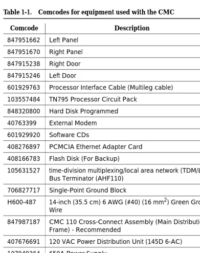
Table 1-1 lists the comcodes for equipment used with the CMC. If “Optional” is checked, the equipment may or may not be necessary, depending on the site configuration.
Table 1-1. Comcodes for equipment used with the CMC
Comcode Description Optional
847951662 Left Panel
847951670 Right Panel
847915238 Right Door
847915246 Left Door
601929763 Processor Interface Cable (Multileg cable)
103557484 TN795 Processor Circuit Pack
848320800 Hard Disk Programmed
40763399 External Modem X
601929920 Software CDs
408276897 PCMCIA Ethernet Adapter Card
408166783 Flash Disk (For Backup)
105631527 time-division multiplexing/local area network (TDM/LAN) Bus Terminator (AHF110)
706827717 Single-Point Ground Block
H600-487 14-inch (35.5 cm) 6 AWG (#40) (16 mm2) Green Ground
Wire
847987187 CMC 110 Cross-Connect Assembly (Main Distribution
Frame) - Recommended
X
407676691 120 VAC Power Distribution Unit (145D 6-AC) X
107949364 650A Power Supply
848082715 Fan Assembly
407745009 Fan Air Filter
848477634 LAN Crossover Cable (RJ45), 12-foot
405362641 120 VAC Power Cord
106278062 Apparatus Blank (Circuit Pack Blank) (158P)
106606536 Integrated Channel Service Unit (ICSU) (120A2) X
107988867 DS1 Loopback Jack (T1 Only) (700A) X
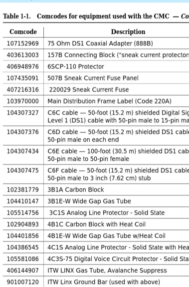
107152969 75 Ohm DS1 Coaxial Adapter (888B) X
403613003 157B Connecting Block (“sneak current protectors”) X
406948976 6SCP-110 Protector X
107435091 507B Sneak Current Fuse Panel X
407216316 220029 Sneak Current Fuse X
103970000 Main Distribution Frame Label (Code 220A) X
104307327 C6C cable — 50-foot (15.2 m) shielded Digital Signal Level 1 (DS1) cable with 50-pin male to 15-pin male
X
104307376 C6D cable — 50-foot (15.2 m) shielded DS1 cable with
50-pin male on each end
X
104307434 C6E cable — 100-foot (30.5 m) shielded DS1 cable with
50-pin male to 50-pin female
X
104307475 C6F cable — 50-foot (15.2 m) shielded DS1 cable with
50-pin male to 3 inch (7.62 cm) stub
X
102381779 3B1A Carbon Block X
104410147 3B1E-W Wide Gap Gas Tube X
105514756 3C1S Analog Line Protector - Solid State X
102904893 4B1C Carbon Block with Heat Coil X
104401856 4B1E-W Wide Gap Gas Tube w/Heat Coil X
104386545 4C1S Analog Line Protector - Solid State with Heat Coil X
105581086 4C3S-75 Digital Voice Circuit Protector - Solid State X
406144907 ITW LINX Gas Tube, Avalanche Suppress X
901007120 ITW Linx Ground Bar (used with above) X
406304816 ITW Linx Replacement Fuse X
103972758 Data Link Protector (1 circuit) X
103972733 Data Link Protector (8 circuits) X
407063478 Electrostatic Discharge (ESD) Wrist Strap
107949364 Lucent online 650A UPS X
407691401 23A2 Alarm Adapter X
Table 1-1. Comcodes for equipment used with the CMC — Continued
Comcode Description Optional
Install the system cabinet
The cabinet can be installed either floor-mounted or wall-mounted. Set the Carrier Address ID as per Figure 1-2 before installing the cabinet.
Verify the carrier address ID
Figure 1-2. Setting carrier address ID (right side)
Proceed to either ‘‘Floor-mount the cabinet’’ on page 1-7 or to ‘‘Wall-mount the cabinet’’ on page 1-8.
OPEN
12
3
4
5
6
swdmdip2 KLC 051399
Floor-mount the cabinet
The cabinet dimensions (with floor pedestal) are 28.5 in. (72.4 cm) high, 24.5 in. (62.2 cm) wide, and 12 in. (30.5 cm) deep. Maintain a service clearance of 12 in. (30.5 cm) on the left, right, and front of the cabinet.
1. Floor-mount the cabinet as per Figure 1-3.
Figure 1-3. Typical floor mount installation
2. Proceed to ‘‘Cable the system’’ on page 1-20.
Figure notes
1. Left panel (floor-mount pedestal)
2. #12 x 1-inch shoulder screws
3. 12 inches (30.5 cm) minimum from nearest object (required to service the circuit packs)
indmflor KLC 110397 1
Wall-mount the cabinet
!
CAUTION:
A fully loaded system weighs 58 lbs (26.3 kg). Use lifting precautions. The unit weighs 29 lbs (13.1 kg) with the doors, power unit, and circuit packs removed.
Install plywood backing on wall. The install technician must provide the plywood and the hardware for mounting.
NOTE:
The following plywood dimensions account for the extra space needed to install the panels on each side of the cabinet. The cabinet is 24 inches (0.6 m) wide and each panel is 12 inches (0.3 m) wide.
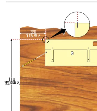
1. Install a 3/4-inch (2 cm) thick sheet of 2 x 4-foot (0.6 x 1.2 m) plywood horizontally onto the wall. See Figure 1-4.
Install cabinet — wall-mount
Figure 1-4. Left panel used as mounting template
The following are procedures for wall mounting the cabinet:
1. Place the template on the wall with the top surface level.
2. Mark two 1/8-inch (0.3-cm) pilot holes in the mounting hole locations.
3. Remove the template from the wall.
4. Drill the two pilot holes.
5. Thread two #12 x 1-inch shoulder screws partially into the holes. FLOOR
indmpnl3 KLC 110397 5" (12.7 cm)
12" (30.5 cm)
6. Set the cabinet onto the wall and align the slots with the shoulder screws. See Figure 1-5. Slide the cabinet to the left to hold it in place. Tighten the screws securely.
Figure 1-5. Typical wall-mount installation
7. Drill 2 lower mounting holes using the cabinet as a template.
8. Thread the 2 lower screws and tighten.
!
CAUTION:
Ensure the right bottom safety screw is in place and tight.
I
Figure notes
Install left and right panels — wall-mount
Figure 1-6. Left and right panel installation
1. Align the cutouts in the panels with the cabinet hinges.
2. Drill a 1/8-inch (0.3 cm) pilot hole into the wall and secure the panels with the #12 x 1-inch shoulder screws.
Figure notes
1. Left panel 2. Right panel
Check AC power and ground
!
CAUTION:
The alternating current (AC) power circuit must be dedicated to the system. The circuit must not be shared with other equipment and must not be controlled by a wall switch. The AC receptacle must not be located under the Main Distribution Frame and must be easily accessible.
!
CAUTION:
The latch only removes direct current (DC) power from the cabinet. Unseating the power supply removes AC power from the power supply, but not from the cabinet. To remove AC power from the cabinet, pull the AC power cord from the AC appliance connector on the rear of the cabinet.
!
CAUTION:
System grounding must comply with the general rules for grounding provided in Article 250 of the National Electrical Code (NEC), National Fire Protection Agency (NFPA) 70, or the applicable electric code in the country of installation.
!
CAUTION:
AC mains wiring and testing must be performed by a qualified electrician and must conform to Article 250 of the NEC, NFPA 70, or the applicable electric code in the country of installation.
Check AC power
Each CMC uses an auto-ranging (85 to 264 VAC) power supply, 47 to 63 Hz, 330 Watts, 4.5 Amps (100-120 VAC) or 2.3 Amps (200 to 240 VAC), at 500 VoltAmps (VA).
The AC power source can be 1 phase of 120 VAC with neutral (100 VAC for Japan) with 15-Amp circuit breaker, or 1 phase of 220 or 240 VAC (200 VAC for Japan) with 10-Amp circuit breaker. The AC cord uses a NEMA 5-15P plug or an IEC 320 plug.
Before powering up the system, check the AC power in the equipment room using a KS-20599 digital voltmeter (DVM) (or equivalent).
1. Measure the AC voltage between the hot and neutral sides of the receptacle.
3. Measure the voltage between the neutral and ground sides of the receptacle.
4. Verify that the meter reads 0 VAC. If not, have a qualified electrician correct the problem.
5. When finished, set the AC main circuit breakers to OFF.
Approved grounds
An approved ground is the closest acceptable medium for grounding the building entrance protector, entrance cable shield, or single-point ground of electronic telephony equipment. If more than 1 type of approved ground is available on the premises, the grounds must be bonded together as required in Section 250-81 of the National Electrical Code.
Grounded Building Steel — The metal frame of the building where it is effectively grounded by 1 of the following grounds: acceptable metallic water pipe, concrete encased ground, or a ground ring.
Acceptable Water Pipe — A metal underground water pipe, at least 1/2 inch (1.3 cm) in diameter, in direct contact with the earth for at least 10 feet (3 m). The pipe must be electrically continuous (or made electrically continuous by bonding around insulated joints, plastic pipe, or plastic water meters) to the point where the protector ground wire connects. A metallic underground water pipe must be supplemented by the metal frame of the building, a concrete-encased ground, or a ground ring. If these grounds are not available, the water pipe ground can be supplemented by 1 of the following types of grounds:
■ Other local metal underground systems or structures — Local
underground structures such as tanks and piping systems
■ Rod and pipe electrodes — A 5/8-inch (1.6-cm) solid rod or 3/4-inch
(2-cm) conduit or pipe electrode driven to a minimum depth of 8 feet (2.4 m)
■ Plate electrodes — Must have a minimum of 2 square feet
(0.185 square m) of metallic surface exposed to the exterior soil
Concrete Encased Ground — An electrode encased by at least 2 inches (5.1 cm) of concrete and located within and near the bottom of a concrete foundation or footing in direct contact with the earth. The electrode must be at least 20 feet (6.1 m) of 1 or more steel reinforcing bars or rods 1/2-inch (1.3 cm) in diameter, or at least 20 feet (6.1 m) of bare, solid copper, 4 AWG (26 mm2) wire.
Approved floor grounds
!
CAUTION:
If the approved ground is inside a dedicated equipment room, then these connections must be made by a qualified electrician.
Floor grounds are those grounds on each floor of a high-rise building that are suitable for connection to the ground terminal in the riser closet and to the cabinet single-point ground terminal. Approved floor grounds may include:
■ Building steel
■ The grounding conductor for the secondary side of the power transformer
feeding the floor
■ Metallic water pipes
■ Power-feed metallic conduit supplying panel boards on the floor ■ A grounding point specifically provided in the building for the purpose
Uninterruptible power supply
A recommended UPS (Uninterruptible Power Supply) may be used for power holdover. The type of UPS depends on the holdover requirements. Total holdover provides for times that vary from less than 10 minutes to up to 8 hours. The UPS must provide surge protection for the CMC cabinet.
1. Connect the UPS to an electrical outlet capable of handling the power requirements of the cabinets:
a. 100 VAC, 4.5 Amps.
b. 120 VAC, 3.8 Amps.
c. 200 VAC, 2.3 Amps.
d. 220-240 VAC, 2.0 Amps.
2. Ensure the cabinet is connected to an “unswitched” or “always on” electrical outlet on the UPS.
3. Connect and administer the UPS. See ‘‘Connect external alarms and auxiliary connections’’ on page 1-53.
NOTE:
If the UPS is wired as recommended, holdover time for each power outage is 1 minute before an automatic shutdown. UPS may handle any
Cabinet power switch
!
CAUTION:
The latch acts as the DC power switch and only removes DC power from the cabinet, not AC power. To remove AC power, pull the AC power cord from the appliance inlet. See Figure 1-7.
Figure 1-7. CMC power supply
Figure notes
1. Latch
evdmrin2 EWS 042500
2
1
EM XFR
ON AU
TO OFF PCM
CIA
MAJOR A
LARM
MIN OR A
LARM
CLOCK
OK R
EMOVE
Connect cabinet grounds and other grounds
Follow these additional grounding requirements:
■ The approved ground wire must be green, 6 AWG (#40) (16 mm2), copper,
stranded wire. This is in addition to the ground wire in the AC power cord.
■ Bond all approved grounds at the single-point ground to form a single
grounding electrode system.
Install the ground block
1. Mount the ground block as shown in Figure 1-8.
2. Connect the cable as shown in Figure 1-9.
Figure 1-8. Ground block installation to right panel Figure notes
1. #12 x 1-inch shoulder screws 2. Single-point ground block
indmingb RPY 012398
1 2
2
Figure 1-9. Typical cabinet grounding Figure notes
1. 6 AWG (#40) (16 mm2) cabinet ground wire
2. Single-point ground block
3. AC load center single-point ground
4. 10 AWG (#25) (6 mm2) wire to coupled bonding conductor (CBC)
5. 6 AWG (#40) (16 mm2) ground wire from single-point ground block to the AC load center single-point ground
4
cadmgrd2 KLC 091499
1
2
Install coupled bonding conductor
The Coupled Bonding Conductor (CBC) provides mutual inductance coupling between the CBC and the telephone cables exposed to lightning. The conductor can be a 10 AWG (#25) (6 mm2) wire tie wrapped to the exposed cables, a metal cable shield around the exposed cables, or 6 spare pairs from the exposed cable.
For a high rise building, connect the CBC to an approved building ground on each floor. To provide the coupled bonding protection:
1. Connect 1 end of the conductor to a telephone cable building entrance protector ground that is connected to an approved ground.
2. Route the conductor next to the exposed telephone cables being protected until it reaches the cross-connect nearest to the telephone system.
3. Position the non-exposed telephone cables at least 12 inches (30.5 cm) away from exposed telephone cables whenever possible.
4. Terminate the other end to the single-point ground block provided for the telephone system.
Connect and route the power cords
!
CAUTION:
The AC power cord may connect to a properly rated power distribution unit, individual AC power receptacles, or to a UPS. See Figure 1-10.
1. Ensure the circuit breakers at the AC load center are OFF.
Figure 1-10. Routing AC power cords to a power distribution unit Figure notes
1. Cabinet AC power cord 2. Surge-protected AC power
distribution unit (120 VAC systems) (optional)
LINE FAULT GROUND OK ALWAYS ON POWER PROTECTION
pcdm6cmc KLC 091499
1
Cable the system
See Figure 1-11 while performing this procedure.
Install Processor Interface cable and TDM/LAN
bus terminators
Figure 1-11. System cable connections
1. Install the TDM/LAN bus terminators.
2. Connect the Processor Interface Cable to the slot 2 connector behind the cabinet. See Figure 1-11.
Figure notes
1. TDM/LAN bus terminator 2. Processor interface cable (slot 2)
cadm2mds KLC 051499
TO
Install main distribution frame
(MDF) and external modem
Install the MDF
!
CAUTION:
The optional MDF is a special 110 cross-connect field that is smaller than the standard 110 cross-connect hardware. Do not install standard 110 hardware inside the right panel.
NOTE:
The depth of any equipment installed inside the right panel must not exceed 2.5 inches (6.3 cm), or the right cover panel will not fit over the right panel.
The optional MDF represents the trunk/auxiliary field.
■ Mount the optional MDF to the right panel using the following procedure:
Bottom-mounted MDF with modem
1. On the rear of the MDF, cut the cable tie securing the top 5 cables to the MDF mounting frame.
2. Mount the MDF to the right panel. See Figure 1-12.
Figure 1-12. Typical bottom-mount MDF and modem cable routing Figure notes
1. Main distribution frame (MDF)
2. External modem
NOTE:
The right cover will not fit if a cable is plugged into slot 1, even though one is shown in
Figure 1-12
3. Processor interface cable (connect P2 to modem)
4. #12 x 1-inch shoulder screw
cadmrpn4 KLC 051399
2
4 5
5
4
4
3
3 2
1
1
2
10 9 8 7 6
10 9 8 7 6
3
1
2
5
6 7
8 4 3
9
10
Install the external modem
The U.S. Robotics external modem is the recommended external modem. DEFINITY ONE systems operate with this modem set to factory default settings.
NOTE:
You may use a locally obtained, type-approved external modem (33.6 Kbps or higher and V.34 protocol). Contact your Lucent Technologies
representative for more information.
!
WARNING:
If you use a modem other than the U.S. Robotics modem, it must be configured in NT.
1. Use the hardware provided with the modem. See Figure 1-12. If top-mounting MDFs, mount the external modem to the plywood in a location which allows the standard connection to the modem cable.
2. Route the modem cable (P2) from the Processor Interface Cable through the cable trough and to the modem.
3. Connect the cable to the modem. See Appendix A, ‘‘Cable Pinouts’’ for the pinout of the modem cable.
4. Plug the modem power cord into an electrical outlet and turn on the modem.
Install equipment room hardware
See DEFINITY Communications System Generic 1 and Generic 3 Main Distribution Field Design, 555-230-630, for more information.
Cross-connect the cabinet to the MDF
1. Cross-connect the ports on the trunk and line circuit packs to the MDF as required. See Figure 1-14.
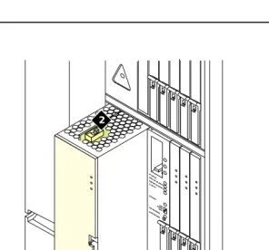
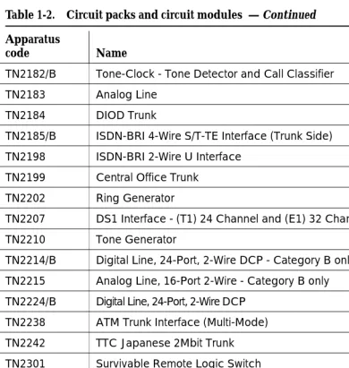
Allowable and non-allowable circuit packs
Table 1-2 lists the circuit packs that can and cannot be used with Release 2.0 of DEFINITY ONE.
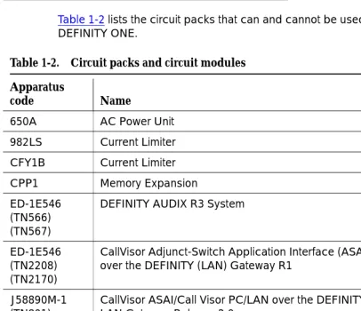
Table 1-2. Circuit packs and circuit modules
Apparatus
code Name Allowable
650A AC Power Unit Yes
982LS Current Limiter No
CFY1B Current Limiter No
CPP1 Memory Expansion No
ED-1E546 (TN566) (TN567)
DEFINITY AUDIX R3 System No
ED-1E546 (TN2208) (TN2170)
CallVisor Adjunct-Switch Application Interface (ASAI) over the DEFINITY (LAN) Gateway R1
No
J58890M-1 (TN801)
CallVisor ASAI/Call Visor PC/LAN over the DEFINITY LAN Gateway Release 2.0
No
NAA1 Fiber Optic Cable Adapter Circuit Pack Yes
TN417 Auxiliary Trunk Yes
TN419B Tone-Clock No
TN420B/C Tone Detector No
TN429/B/C/D Analog Direct Inward/Outward Dialing (DIOD) Central
Office Trunk
Yes
TN429C Analog Central Office Trunk Yes
TN429D Analog DIOD Trunk - Analog Loop Start Yes
TN433 Speech Synthesizer Yes
TN436B Direct Inward Dialing Trunk Yes
TN437B Tie Trunk Australia (future availability) Yes
TN438B Central Office Trunk Yes
TN439 Tie Trunk Yes
TN447 Central Office Trunk Yes
TN457 Speech Synthesizer Yes
TN459B Direct Inward Dialing Trunk Yes
TN464F DS1 Interface - T1, 24 Channel - E1, 32 Channel Yes
TN465B/C Central Office Trunk Yes
TN467 Analog Line Yes
TN468B Analog Line Yes
TN479 Analog Line Yes
TN553 Packet Data Line Yes
TN556C/D Integrated Services Digital Network -Basic Rate
Interface 4-Wire S/T-NT Interface (ISDN-BRI)
Yes
TN568 DEFINITY AUDIX Slim No
TN570B/C Expansion Interface No
TN572 Switch Node Clock No
TN573B Switch Node Interface No
TN574 DS1 Converter - T1, 24 Channel No
TN577 Packet Gateway No
TN722B DS1 Tie Trunk Yes
TN725B Speech Synthesizer Yes
TN726B Data Line Yes
TN735 Multibutton Electronic Telephone (MET) Line Yes
TN742 Analog Line Yes
Table 1-2. Circuit packs and circuit modules — Continued
Apparatus
code Name Allowable
TN744B/C Call Classifier No
TN744D Call Classifier - Detector Yes
TN746B Analog Line Yes
TN747/B Central Office Trunk Yes
TN748B/C/D Tone Detector No
TN750B Announcement No
TN750C Announcement Yes
TN753/B Direct Inward Dialing Trunk Yes
TN754/B/C Digital Line 4-Wire DCP Yes
TN755/B Neon Power Unit No
TN756 Tone Detector/Generator No
TN758 Pooled Modem Yes
TN760B/C/D/E Tie Trunk Yes
TN762/B Hybrid Line Yes
TN763B/C/D Auxiliary Trunk Yes
TN765 Processor Interface No
TN767B/C/D/E DS1 Interface - T1, 24 Channel Yes
TN768 Tone-Clock No
TN769 Analog Line Yes
TN771/D Maintenance/Test No
TN772 Duplication Interface No
TN775/B/C Maintenance No
TN776 Expansion Interface No
TN777B Network Control No
TN778 Packet Control No
TN780 Tone-Clock No
TN787F/G/H/J/K Multimedia Interface No
TN788B Multimedia Voice Conditioner No
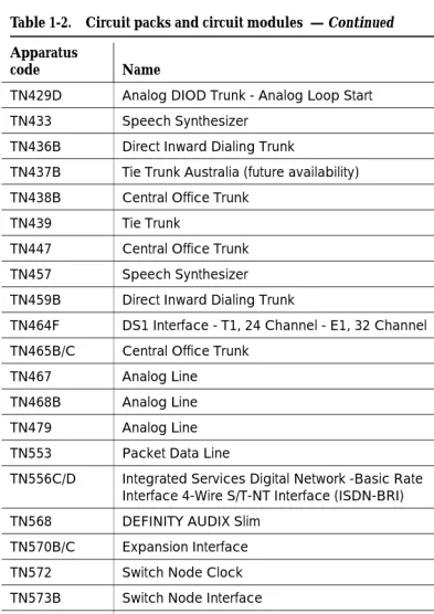
Table 1-2. Circuit packs and circuit modules — Continued
Apparatus
code Name Allowable
TN789 Radio Controller Yes
TN790B Processor No
TN791 Analog Line Yes
TN792 Duplication Interface No
TN793 Analog Line, 24-Port, 2-Wire Yes
TN794 Network Control/Packet Interface (NetPkt) No
TN795 Processor Yes
TN798B Processor No
TN799/B Control LAN (C-LAN) Yes
TN801 LAN Gateway Interface No
TN802/B Internet Protocol (IP) Trunk Yes
TN1648/B System Access/Maintenance No
TN1650B Memory No
TN1654 DS1 Converter - T1, 24 Channel/E1, 32 Channel No
TN1655 Packet Interface No
TN1656 Tape Drive No
TN1657 Disk Drive No
TN2135 Analog Line Yes
TN2136 Digital Line 2-Wire DCP Yes
TN2138 Central Office Trunk Yes
TN2139 Direct Inward Dialing Trunk Yes
TN2140B Tie Trunk - Hungary, Italy Yes
TN2144 Analog Line Yes
TN2146 Direct Inward Dialing Trunk Yes
TN2147C Central Office Trunk Yes
TN2149 Analog Line Yes
TN2180 Analog Line Yes
TN2181 Digital Line 2-Wire DCP Yes
Table 1-2. Circuit packs and circuit modules — Continued
Apparatus
code Name Allowable
TN2182/B Tone-Clock - Tone Detector and Call Classifier No
TN2183 Analog Line Yes
TN2184 DIOD Trunk Yes
TN2185/B ISDN-BRI 4-Wire S/T-TE Interface (Trunk Side) Yes
TN2198 ISDN-BRI 2-Wire U Interface No
TN2199 Central Office Trunk Yes
TN2202 Ring Generator No
TN2207 DS1 Interface - (T1) 24 Channel and (E1) 32 Channel Yes
TN2210 Tone Generator No
TN2214/B Digital Line, 24-Port, 2-Wire DCP - Category B only No
TN2215 Analog Line, 16-Port 2-Wire - Category B only No
TN2224/B Digital Line, 24-Port, 2-Wire DCP Yes
TN2238 ATM Trunk Interface (Multi-Mode) No
TN2242 TTC Japanese 2Mbit Trunk Yes
TN2301 Survivable Remote Logic Switch No
TN2305 Asynchronous Transfer Mode (ATM) Trunk Yes
TN2306 ATM Interface (Single-Mode) No
TN2308 Direct Inward Dialing Trunk No
TN2464 DS1 Interface - T1, 24 Channel - E1, 32 Channel Yes
TN2793/B Analog Line 24-Port Yes
Table 1-2. Circuit packs and circuit modules — Continued
Apparatus
code Name Allowable
Circuit pack installation
!
CAUTION:
When handling circuit packs or any components of a DEFINITY ONE system, always wear an authorized wrist ground strap.Connect the strap to the ground connector provided on the system cabinet.
NOTE:
All of the circuit pack slots in the CMC are “universal slots.” Any slot can contain any type of port circuit pack.
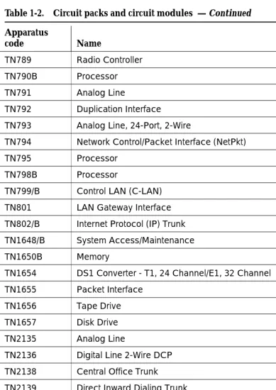
Circuit pack slot loading
1. Install the TN795 Processor circuit pack in slot 2 of the cabinet. See Figure 1-13.
2. A TN744D Call Classifier/Tone Detector circuit pack is required. Install the TN744D into any port slot except for slots 1 and 2 (slot 3 is preferred but not required.)
Figure 1-13. Cabinet and slot numbering
1. Slots 1 - 5
2. Slots 6 - 10
3. 650 A Power Unit
4. For Flash Disk (PCMCIA)
scdmlft2 KLC 091399
5 10
1 2 3 4 6
2
1 3
4
EM XFR ON AUTO OFF PCMCIA MAJOR ALARM MINOR ALARM CLOCK
OK REMOVE
SHUTDOWN
T N 7 9 5
.
1. Cross-connect the port circuit packs to the MDF. See Figure 1-14.
Table 1-3. Circuit pack installation order (loading)
Function Apparatus code Load from Notes
Processor TN795 Slot 1 and 2
Call Classifier/Tone Detector
TN744 Slot 3
Announcement TN750C Any slot
Speech Synthesizer TN725B Any slot
DS1/E1, ISDN PRI TN464F, TN767E,
TN2242, TN2464
Lower Right Maximum of 7 ISDN-PRI. Total number of ISDN-PRI plus number of ISDN-BRI circuit packs must not exceed 7.
ISDN-BRI Trunk TN2185 Lower Right Maximum of 4
CO Trunk TN747B, TN465C,
TN2199, TN2147C, TN2138, TN438B
Lower Right
DID Trunk TN753, TN2139, TN2146,
TN436B, TN459B
Lower Right
Tie Trunk TN760E, TN458, TN497,
TN2140B
Lower Right
Auxiliary Trunk TN417 Lower Right
Modem Pool TN758 Lower Right
Data Line TN726 Upper Left
Digital Line TN754C, TN2181,
TN2224/B,
Upper Left
Analog Line TN746B, TN2135, TN467,
TN2144, TN2149, TN2180, TN2183, TN2215, TN468B,TN791, TN793, TN2793,TN2214
Upper Left
Hybrid Line TN762B Upper Left
MET Line TN735 Upper Left
Radio Controller TN789 Upper Left
ISDN-BRI 4-Wire S/T-NT Line (A-Law)
TN556C/D
TN744D
Figure 1-14. Example MDF connections w idfccf2 EWS 042799 4 1 10 19 4 13 22 2 11 20 5 14 23 3 12 21 6 15 24 9 18 7 16 25 8 17 Port Tie Trunk Port MET Line
4 4Port
Off-premises circuit protection
Protection from hazardous voltages and currents is required for all off-premises (out of building) trunks, lines, and terminal installations. Both over-voltage protection (lightning, power induction, and so forth), and sneak current
protection are required. Sneak current protectors must be either UL listed/CSA certified, or must comply with local safety standards.
Sneak current protectors must have a maximum rating of 350 mA and a minimum voltage rating of 600V, or as required by local regulations. The following devices protect the system from over-voltages:
■ Analog trunks use the 507B sneak protector or equivalent. Over-voltage
protection is normally provided by the local telephone company.
■ Analog voice terminals use one of the following types of combined
over-voltage and sneak current protection, or equivalent:
— Carbon block with heat coil for UL code 4B1C
— Gas tube with heat coil for UL code 4B1E-W
— Solid state with heat coil for UL code 4C1S
■ DCP and ISDN-BRI terminals use the solid state 4C3S-75 with heat coil
protector, or equivalent.
■ DS1/T1 circuits require isolation from exposed facilities. This isolation may
Install sneak fuse panels
Sneak current protection is required between the incoming RJ21X or RJ2GX network interface and the system for both trunk and off-premises circuit packs. The model 507B sneak current fuse panel, or equivalent, is recommended for sneak current protection. See Figure 1-15.
Figure 1-15. Model 507B sneak fuse panel Figure notes
1. 507B Sneak current protector (price element code: Comcode 107435091)
2. 25-pair male connector (In) (Comcode 846300994)
3. 25-pair female connector (Out) (Comcode 846300994)
4. 220029 fuses (inside panel). Use a small screwdriver to pry top cover off
Sneak Current Protector
Each column of sneak fuse panels requires approximately 8 inches (20 cm) of horizontal wall space. Connector cables connect the network interface to the sneak fuse panel. Also, use 157B connecting blocks equipped with SCP-110 protectors for sneak current protection.
NOTE:
Sneak current protectors with a rating of 350 mA at 600 Volts must be UL listed for United States installations and Canadian Safety Association (CSA) certified for Canadian installations. The panel contains two 25-pair
connectors, fuse removal tool, and fifty 220029 Sneak Fuses (and 2 spares). Use the SCP-110 protectors with 110-type hardware and on the 507B Sneak Fuse Panel. The SCP-110 Protectors can be ordered
separately and installed on the 157B connecting block. Fifty protectors are required per block.
Table 1-4 is a pinout of the cable wiring and associated fuse numbers.
Table 1-4. Sneak fuse connector pinout
Connector Pin Numbers
Pair/Fuse Number
26/1 1
27/2 2
28/3 3
29/4 4
30/5 5
31/6 6
32/7 7
33/8 8
34/9 9
35/10 10
36/11 11
37/12 12
38/13 13
39/14 14
40/15 15
41/16 16
42/17 17
43/18 18
44/19 19
45/20 20
46/21 21
47/22 22
48/23 23
49/34 24
Label the main distribution frame
Figure 1-16 shows the graphic symbols used on the supplied labels for the system, cross-connections, information outlets, and cables.
1. Write the floor and building identification on each label as required.
2. Insert the labels into the plastic holders.
3. Snap the holders into the appropriate locations on the MDF.
Figure 1-16. Label graphic symbols and nomenclature
4. Label the cables as required using the supplied labels. Label code number 220A (comcode 103970000) contains all required labels.
Figure notes
1. Floor and building identification
2. Cabinet
3. Carrier
4. Slot
5. Information outlet
6. Site/satellite closet
7. Tie circuit
8. Floor
9. Building
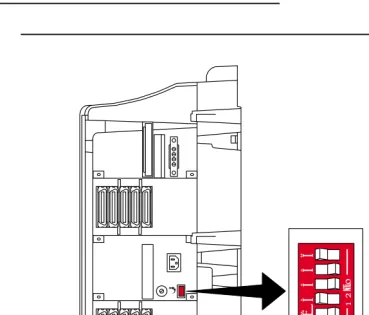
Set ringing option
Figure 1-17. Ringing option selection Figure notes
2 - Ringing option switch
NOTE:
Look at the label on the side of the power supply to see how to set switch.
evdmrin2 EWS 042500
2
1
EM X FR
ON AU
TO OFF PCM
CIA
MAJOR A
LARM
MINOR
ALA RM
CLOCK
OK R
EMOVE
SHUTDOW
Figure 1-18. TN795 circuit pack faceplate Figure notes
1. PCMCIA slots
2. Red LED
3. Green LED
4. Amber LED
5. PCMCIA In-Use LED
6. Emergency Transfer Switch
7. Shutdown Complete — safe to pull board when green LED is on
8. Shutdown Switch — gracefully shuts down system
Do Not Remo
ve Boar
d Unitl
Shutdo
wn Is Complete
ckdfpcm3 EWS 040300
On Auto Off
In Use
Do Not Remo
ve Maj Alarm Min Alarm Clock Emergency Transfer genc Complete Shutdown 6 7 8 3 4
Do Not Remo
ve
When In Use
1
2
Install and wire telephones and other
equipment
NOTE:
Only 1 pair of wires is available for emergency transfer, and 1 pair of wires is available for Attendant Console power.
The wiring procedures are similar for most DEFINITY system telephones and other equipment.This chapter provides wiring examples for similar installation procedures. Actual wiring procedures may vary at each site.
The system can connect to all DTE terminals. The system can have RS-232 (or EIA-232) or DCP interfaces.
All wiring pinouts for port circuit packs are in the tables at the end of this chapter.
See Figure 1-32 for punch-down information for common circuit packs. The figure shows the colors of the punch-downs and is best viewed from CD-ROM or on-line.
After installing the hardware, the data for the system and telephone features is administered. These procedures are provided in DEFINITY Enterprise
Communications Server Release 8.2 Administrator’s Guide, 555-233-506.
Telephone connection examples
The 302C1 Attendant Console (AC) describes a typical telephone connection. This information is typical of the 603E, 84xx (4-wire), and 94xx telephones. The AC always requires auxiliary (adjunct) power (-48 VDC). See Figure 1-19. Only 1 console can be powered by the system through the auxiliary(AUX) connector. The primary console should be powered from the system so it has the same power failure backup as the system.
The maximum cabling distance for the console powered fr