APPLICATION OF COMPUTER SIMULATION METHODS FOR THE
ANALYSIS OF FUEL ASSEMBLIES BEHAVIOUR UNDER THERMAL
MECHANICAL LOADING
Alexey Kiselev1), Alexander Kiselev1)and Alexander Tutnov1)
1)Russian research center“Kurchatov institute”,Moscow,Russia
ABSTRACT
The investigation of stressed straining state (SSS) of design elements of fuel assembly (FA) under operational loads, which are characterized by influence of the mechanical forces, of temperature and of radiating factors, and also of vibration, is an important task. For an assessment of thermal-mechanical stability and strength of FA of TVSA type it is needed a special calculation and experimental investigations which are carried out on the basis of numerical FA-models development. The developed three-dimensional FA-model describes in detail all geometry features of FA design elements– spacergrids(SG)with cellsassembled using spotwelding,fuelrods,bottom and top units.Such approach has allowed refuse of introduction of simplifying hypotheses, for example, simulation of spacer grid by a continuous plate, which reduces accuracy of modeling. The developed models allow take into account main mechanisms of FA design elements interconnections features such as friction and sliding of fuel rods trough SG-cells. The number of degree of freedoms of FE models exceeds of 20 millions. The calculations were carried out with using of the computer code UZOR 1.0 developed by RRC “Kurchatov institute”realizing super-elementalgorithm and paralleltechnology,atwhich one task is solved simultaneously on several computers. Some results of calculations of deformation and stresses distribution of FA TVSA-T design elements are given in the paper as an example of efficiency of developed technique.
INTRODUCTION
Fuel assemblies of VVER reactors are operated under complicated working conditions characterizing by action of following depending on time factors:
- non-uniform non-stationary temperature fields; - non-uniform non-stationary neutron fluence fields;
- fuel swelling and irradiation induced growth of design elements;
- friction forces associated with the sliding of shortening or growing fuel rods in cells of SG; - thermal and irradiation creep;
- axial compressive load of spring block.
As a result of influence of mentioned above factors FA are contorted during operation and high level of stresses arises in design elements of FA skeleton. It can result in destruction of FA design elements and also in changing of gaps between FA in a reactor core. As a consequence, it influences on the neutron-physical and thermo-technical characteristics of reactor core. Therefore the problems of FA curvature and strength assessment are rather actual.
Fuel assemblies of VVER reactor have a complicated geometry -Fig.1. The main design element are:
1 - dismountable upper head with a spring block;
2 - rigid bearing skeleton (spacer grids (SG), guide tubes (G), angles in the corners of FA hexahedron);
3 - fuel rods assembly; 4 - bottom end plug; 5 - bottom support grid.
The bearing skeleton of FA provides a rigidness and strength of construction. It takes the forces and bending moments created by a friction forces in the SG cells by sliding fuel rods, which can grow due to irradiation, and also it takes load of spring block and inner load associated with a non-uniformity of thermal and neutron fluence fields. The bearing skeleton of various FA incorporates of 8 - 15 SG and of 18 guide tubes (GT) and central tube making from Zr-alloys, at which spacer grids are joined by using spot welding. The bearing skeleton of FA of TVSA-T type consists from eight SG and from angles in the corners of FA hexahedron. The central tube and GT are fastened usually with the help of carving connections to the bottom support grid, which is welded to the bottom end plug. GT and central channel are fixed at FA head and works under compressive loading from an upper spring block, which counteracts against
1
2
3
4
5
emersion of FA in the coolant torrent.
Spacing of the fuel rods in FA is carried out with the help o SG of a cellular type from 110 Zr-alloy with cell's height of 20 or 35 mm and mean value of diametrical tightness between cell and fuel rod of about 0,1 mm.
The fastening of fuel rods with a purpose of exception their moving in axial direction are realized in the bottom support grid using collets.
The fuel cycles for several types of FA have a different extent on time. The four-years fuel cycles with a four times of FA re-loading in reactor core are most frequently now. The longer fuel cycles are developed at present time with the purpose of increase of efficiency of fuel exploitation.
There are some stages during FA operation between re-loading of reactor core: warming up, working on nominal mode, cooling before re-loading. There also presence regimes with a changing of reactor power with corresponding alteration of temperature and of neutron fluence distribution in separate FA and in the reactor core as a whole.
The changing on the time and in the volume of FA of temperature and neutron fluence distribution results in appearance of additional strains and stresses in the design element of FA depending on time. It is needed to know the kinetics of a stressed-straining state (SSS) during the fuel cycle to carry out on the next step an assessment of strength of most loaded FA design elements. There is entered an assumption to choice the most loaded from working in the reactor core FA, that the most higher of deformation and stresses values are realized in FA with a maximum of burnup level. The neutron and temperature fields in the selected FA are defined using detailed neutron-physical calculation. The obtained results are the neutron and temperature distribution along each fuel rod, which are approximated on the mechanical finite element model of FA with the help of special procedure.
The task of the SSS calculation of FA under operation is a non-linear, non-stationary, elastic-plastic-viscous problem.
METHODS OF SOLUTION
The calculations of stresses and strains distribution of complicated volumetric structures taking in to account all listed above features of FA operation are possible only with application of modern numerical approaches of computer simulation (finite-elements and super-elements methods).
The main reason of loading of the bearing skeleton of FA is the friction in pairs "fuel rod - SG cell". The level of the friction forces is increased at the initial phase of operation until the threshold values of forces will be reached and the fuel rod could move through SG cell. The critical level of friction forces is decreased with increasing of time of operation because of stresses relaxation in SG cells due to creep processes. To provide definite friction forces in pairs "fuel rod -SG cell" the fuel rods are connected with the cells using special contacting elements with a fictive properties of elastic-plastic material with a low value of Young modulus. The matching of elastic modulus and effective yield stresses for contacting elements is performed with the help of testing models. The level of stresses is increased in the contact elements by radiation growing of fuel rods. If the yield limit is not reached the material of contact element works as elastic material completely transferring the forces from fuel rod to cell of SG. It corresponds to the sliding absence and to the simultaneously deforming of fuel rod and SG cell. If the stresses in contact element reach yield limit the axial forces in the fuel rod cease growing remaining constant value in spite of further fuel rod lengthening. It corresponds to the condition of the rod sliding trough SG-cell and the deformation occurs exclusively due to plastic without hardening in the contact element. The phase of fuel rod shortening can begin after lengthening phase in transitive modes of operation, for example due to temperature fields changing. The stresses in the contact element are dropped and it works again as an
elasticmaterialso long asthestressesofreversed sign don’treach theyield limit.
Thus, the task of simulation of the fuel rod sliding in SG-cells is reduced to the solution of nonlinear elastic-plastic problem under complex load including stages of loading and unloading. The mathematical equations of the theory of plasticity and iterative step-by-step algorithm of a method of initial stresses are used with this purpose.
The features of FA design having complex three dimensional geometry have required development of the finite element model with more then 20 millions degrees of freedom. Besides the simulation of FA behaviour under above described nonlinear, non-stationary load demands the organization of a multi-steps calculation process, on each of which the iteration process is organized with regard of physical non-linearity.
Realization of the stresses analysis with application of such model with use of traditional FE algorithm is rather difficult or impossible because the requirements of computer resources are excessively high. For the decision of a problem(task) The numerical algorithm based on a super-elements approach [1] and the computer code UZOR 1.0 [2], which new version allows to perform calculations simultaneously (parallel) on a several computers connected by a local network, are developed to solve mentioned above problem. Advantages of the super-element method are shown most distinctively in the context of consideration designs having high number of repeated fragments. All repeated parts of similar geometry are represented by one typical super-element, that essentially decreases the task performance period. It
isimportantadvantageofSEM forconsidered task – simulation ofbehaviour of FA, because it consists from a large number of design elements with a similar geometry, such as fuel rods, cells of spacer grids, guide tubes. Therefore application of SE-algorithm in this case will be rather effective.
} { } ]{
[K P , (1)
where
P is a vector of loading increment in the nodes of FE model, [K] is a global rigidity matrix of FE model, the number of the rows and columns in which are equal to number of FE model degrees of freedom (DOF). The practically irresistible difficulties arise by allocation of the matrixes corresponding full-scale models in the main memory of a computer. The technique based on the super-elements method (SEM) allowing reduce considered matrixes size stage by stage is developed to resolve these problems. The gist of SEM consists in representation of an object as set of super-elements (SE) of several levels, which are built on the lowest level from usual FE. Concerning the model of FA the separate SG-cells or groups of cells can be considered as super-elements. The rigidity matrix of a super-element consists from blocks corresponding internal and boundary nodes of SE [1]: s i s i ss si is ii P P q q K K K K , (2)
whereiis the index of inside node parameters,sis the index of boundary node parameters, {qi}is the vector of
displacements of inside nodes, {qs} is the vector of displacements of boundary nodes, {Pi} is the vector of loads applied
to inside nodes, {Ps}is the vector of loads applied to boundary nodes.
The dependencies for determination of a reduced matrix of rigidity [k] and a vector of nodal loads {p} of SE with the number of components equal to the quantity of boundary degrees of freedom are written as [1]:
k Kss Ksi Kii1Kis FT K F
P Ps
Ksi Kii1
Pi
FT
P , where
E K KF ii 1 is .
Thus, the super-element determines nodal parameters of inside nodes from parameters of boundary nodes. In this case, the full number of nodes of the model, considered at each subsequent level of super-elements is significantly reduced, since only those boundary nodes are considered, which completely describe interaction of super-elements in their assembly.
The percentage of boundary nodes in SE of the first level is usually equal to 5-20% from whole number of nodes. In a case of FA model this ratio is even less since SG-cells, which can be considered as separate SE, are connected in the welded points and have very small amount of boundary units. For example, the transition from the first level of SE to the second level reduces the number of DOF of TVSA-T FA model from ~3900000 up to ~72000. It is possible to apply the described procedure to assemble super-elements of lower level in super-elements of the next levels and extra reduce sizes of matrixes. After the solution of the linear algebraic equations system for uppermost level of SE and determination of boundary nodes displacements of SE of previous level the displacements of internal nodes are calculated. The nodes displacement values, on which components of stresses and strains are defined, for initial FE model can be obtained applying this procedure consistently for all levels of SE. This stage of algorithm is called reverse course.
Itisimportantto emphasize,thatSEM isastrictmathematicalprocedure,which doesn’tbring an additional
inaccuracy in the final results, in spite of, for example, a substructure method. Except for essential reduction of time of calculation there take place decreasing of approximation error due to decreasing of the whole number of mathematical operations at the large matrix inversing.
One of essential advantages of SEM is that it is very convenient for creating of the parallel computing system because the calculation of reduced rigidity matrixes of each SE can be realized within the framework of separate thread or process. Thus expenses of computer resources for synchronization of such processes and data exchange between processes are rather low. It allows using of rather inexpensive network equipment.
There are two levels of parallel data processing algorithms in the computer code UZOR 1.0. The first level provides multi-threading data processing on the one workstation with several processors or kernels. The Client-Server technology is applied for realization of the second level parallel algorithms to provide distribution of data processing between separate workstation connected by local network. The Server-program organizes the calculating process, the data exchange and synchronization between clients program, which are started on a network computers. The algorithms realizing several stages of FEM or SEM approaches - calculation of reduced rigidity matrixes of SE, linear algebraic system solution, definition of the displacement of nodal point of the whole model, calculation of stresses - are carried out
by Client’sapplications. The Server-program organizes step-by-step iteration procedure with a cycles on the SE-levels and on SEin each levelatthe“directrun”(determination of rigidity matrixes and vectors of loads for super-elements)
and the“reverserun”oftheSEM approach (displacementand stressesdetermination).
The automatic start of Clients applications on the network computers are carried out of a network according to the list of connected workstations after the Server program has started. The communication of each of Clients with the Server provides by means of two channels of messages and data exchange of "PIPE" type in operational systems Windows NT, 2000, XP. It is necessary to note, that such schema of parallel algorithm involves simultaneously not only processors of workstations, but also hard disks stores. The information from HDD is read out by each Client independently, that essentially accelerates calculation process for large-scale FE models demanding reading and writing of several tens Gigabytes of information on each iteration.
Now there are six units of one and dual-processor computers productivity of 2,6-3,8Ghzwith 2 – 8 Gb of main memory in our local network.
The described above principles of the parallel computing system building are realized in a last version of
computercodeUZOR 1.0 developed in Russian research center(RRC)“Kurchatov institute”.In ouropinion,theoffered
approaches are rather flexible and are optimal from the point of view of the equipment cost. The developed software can involve in calculation process up to 48 workstations, which had been used earlier individually by members of work group. In a process of steaming of the equipment separate system blocks can be replaced and besides additional computing capacities can be connected at any moment. Application of the given algorithm for FA behavior simulation reduces the time of calculation in ~4,5 times by using of 5 Clients-programs. Full calculation of a four-years fuel cycle of the TVSA-T fuel assembly have included 28 steps on loading and 10-50 iterations on nonlinearity on each step and have required of about 120 hours.
THE MODEL OF FUEL ASSEMBLY
The big number of design elements of FA interconnecting on intricate ways among themselves causes necessity of building of detailed 3D FA model for investigation of the stresses distribution and the strength assessment under
thermal-mechanicalload.Thereisconsidered oneofmodelsofFA – ofTVSA-T type.
The FE model of TVSA-Tincluding allbasicdesign elements– 312 fuelrods,18 guidestubes,8 spacergrids,6 anglesofrigid skeleton,thebottom supportgreed,thebottom unit,thetop spring block (issimplified)– isshown on
fig.2. All calculations, which results are given below, was performed using this model.
The skeleton of TVSA-T with spacer grids is shown on fig.3 and also the skeleton of TVSA-T without SG (to not shade the inner elements) is shown on fig.4.
The fragment of the spacer grid model is on fig.5. The cells in the model corresponds exactly which real geometry. Each of cells is collected in SG by means of 12 welded points by the area of about 1 mm2.
The fragment of model including bottom unit of TVSA-T (fuel rods are not shown) is given on fig.6. Characteristic perforations for coolant flow in the bottom support greed and also geometry of angles of skeleton are visible.
Similar models are developed and for other types of FA. The dimension of models reaches of about 7,5 millions nodal points and more than 21 millions DOFs, that demands using of special numerical methods of calculation described above.
RESULTS OF CALCULATION
The results of calculations of stressed straining state of TVSA-T FA at the half of the first Year of operation, when the internal forces due to intensive friction are maximal,aregiven on fig.7 – fig.9.Thenon-uniform distribution of temperature and neutron fluence corresponding to considered time instance are shown on fig.7, fig.8.There are not shown fuel rods on figures of stresses distribution to better view on the skeleton design elements, but they was presented in the model and was taken in to account in calculations.
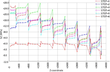
The plots of axial stresses distributions on the height of FAin basicdesign elementsoftheskeleton – guides tubesand angles– arepresented on fig.10 and fig.11 on thefirstyearofatypicalfour-yearsfuelcycle.Theplotsinclude
several graphics corresponding to the number of calculation steps (and to the time of operation) for most loaded angle and guide tube. The similar information is obtained for other stages of the fuel cycle. It allows to analyze the stresses level and to estimate strength of most loaded design elements of FA TVSA-T during all operation period.
It is necessary to pay attention, that the tensioning stresses in guide tubes and angles are increased stepped after
each SG,thatistheconsequenceoffriction forcesaction in pairs“fuelrod – SG-cell”.Thestressesvaluesin GT and
angles have a maximum not always in the first span of FA between the bottom support grid and the first SG. It is possible
to makeaconclusion analyzing theplots,thatthethreshold leveloffriction forceshaven’treached and thesliding fuel rodsthrough SG-cellshaven’thappened in thelowerspansofFA in thefirsthalfofthefirstyearofoperation.The
reason of this is the combination of the following factors:
-
low values of accumulated neutron fluence and consequently small difference in deformations of fuel rods and of skeleton of FA;-
non-uniformity of the temperature and neutron fields;-
rather high threshold values of friction forces due to small stresses relaxation in SG-cells;Fig. 2 The finite element model of FA of TVSA-T type (3957216 nodal
points).
Fig. 3 The model of the rigid skeleton of TVSA-T.
Fig. 5 The model of spacer grid (cells are assembled using 12 welding point).
Fig. 6 The FE model of bottom end plug.
The maximal tensioning axial stresses in GT and angles are formed in the second or third span counted from the bottom of FA in the beginning period of operation. The friction forces reduction and thermal and radiation deformation accumulation result in the sliding of fuel rods trough SG-cells during the second half of second year of operation. The maximum values of axial stresses in FA-skeleton are realized in that case in the bottom span oh GT and angles, however their level are not very high, since the friction forces at this time are essentially decreased.
Fig. 7 The temperature distribution in TVSA-T at the end of the first half of the first year of the four-years fuel
cycle.
Fig. 8 The neutron fluence [1/sm2] distribution in TVSA-T at the end of
the first half of the first year of the four-years fuel cycle.
Fig. 9 The axial stresses distribution in TVSA-T at the end of the first half of the first year of the four-years fuel
-4
0
0
-0 +4
0 0 + 8 0 0 + 1 2 0 0 + 1 6 0 0 + 2 0 0 0 + 2 4 0 0 + 2 8 0 0 + 3 2 0 0 + 3 6 0 0 + 4 0 0 0 -4.0 +0.0 +4.0 +8.0 +12.0 +16.0 +20.0 +24.0 +28.0 +32.0 +36.0 +40.0 STEP=1 STEP=2 STEP=3 STEP=4 STEP=5 STEP=6 Z-coordinate SZ [M Pa ]
Fig. 10 Axial stresses distribution on the height of skeleton angle on the first year of the fouryears fuel cycle (STEP1 -beginning of the first year, STEP2 - end of the first quarter of the first year, STEP3 - end of the second quarter of the first
year,STEP4 -end ofthe third quarterofthefirstyear,STEP5 -end ofthefirstyear,STEP6 – re-loading ofFA attheend
of the first year)
-0 +4
0 0 + 8 0 0 + 1 2 0 0 + 1 6 0 0 + 2 0 0 0 + 2 4 0 0 + 2 8 0 0 + 3 2 0 0 + 3 6 0 0 + 4 0 0 0 -12.0 -8.0 -4.0 +0.0 +4.0 +8.0 +12.0 +16.0 +20.0 +24.0 +28.0 STEP=1 STEP=2 STEP=3 STEP=4 STEP=5 STEP=6 Z-coordinate S Z [M P a]
Fig. 11 Axial stresses distribution on the height of guide tube on the first year of the fouryears fuel cycle (STEP1 -beginning of the first year, STEP2 - end of the first quarter of the first year, STEP3 - end of the second quarter of the first
year,STEP4 -end ofthe third quarterofthefirstyear,STEP5 -end ofthefirstyear,STEP6 – re-loading ofFA attheend
NOMENKLATURE
FA = fuel assembly SG = spacer grid GT = guide tube
SSS = stressed-straining state SE = super-element SEM = super-element method FE = finite element
SUMMARY AND CONCLUSION
1. The technique of calculation and the three-dimensional finite element models of fuel assembly of various types are developed for the analysis of deformation processes of FA in various modes of operation. The friction forces in
pairs“fuelrod – SG-cell”,non-uniform varying in timefieldsoftemperatureand irradiation areconsidered asthemain
loading factors. The calculations in a nonlinear problem statement were carried out with using of the computer code
“UZOR 1.0”,realizing thesuper-elementalgorithm and parallelmethodsofdataprocessing.
2. An example of calculations of the stressed-strained state of FA of TVSA-T type for four-years fuel cycle is presented. It is shown, that the maximal loading on the rigid skeleton is reached during the first year of operation, when there are fuel rod sliding in cells of spacer grids in the bottom span of FA with maximal friction forces. The sliding of fuel rods in cells of SG at earlier stages of operation does not occur.
3. The developed model and technique of calculations based on super-element algorithm has allowed to take into account non-uniformity of radiating and temperature fields in the volume of FA and their dependence on time. As a result it was shown, that the design elements of the skeleton are loaded in a various degree and the fuel rods sliding through SG-cells happen not simultaneously, that results in decreasing of loading on the FA skeleton and creates additional safety margins.
4. The developed models and software are rather perspective for study of behaviour of fuel assemblies of various designs in stationary, transitive and emergency conditions of operation. It allows to simulate effectively non-linear deforming of a design in view of all basic loading factors.
REFERENCES
1. Postnov, V.A., Taranuha N.A., Module elements method in calculations of ship designs, Sudostroenie, Leningrad, 1990.
2. Kiselev, A.S., Kiselev, A.S.,Danichev,V.V.,“Thesummary oftheprogram UZOR 1,”Questionsofanuclear science and engineering, vol. 1, 1999, pp. 109-113.

![Fig. 8 The neutron fluence [1/sm2]distribution in TVSA-T at the end of](https://thumb-us.123doks.com/thumbv2/123dok_us/1229968.1155437/6.612.96.515.329.684/fig-neutron-fluence-sm-distribution-tvsa-t-end.webp)