Express 5210
Frame Relay Service Unit
User Manual
61200208L1-1A October 1999
1200208L1 Base Unit 1202187L1 Dual FXO Card 1202188L1 Dual FXS Card 1202189L1 Dual E&M Card
1204001L1 4-wire SW56 DBU Card 1204002L1 V.34 DBU Card
This product includes software developed by the University of California, Berkeley, and its contributors.
901 Explorer Boulevard P.O. Box 140000 Huntsville, AL 35814-4000
Phone: (256) 963-8000 © 1999 ADTRAN, Inc. All rights reserved.
About This Manual
This manual is arranged so you can quickly and easily find the information you need. The following is an overview of the contents of this manual:
• Chapter 1, Introduction, familiarizes you with frame relay networks and
Express 5210 highlights. The chapter also gives a brief explanation of options that may be purchased for use with the Express 5210.
• Chapter 2, Installation, describes the Express 5210 connectors (pin assignments are given in the appendix Pinouts on page A-1) and provides an installation diagram. • Chapter 3, Menu Navigation, explains how to operate your Express 5210 using
either the front panel or a VT 100 terminal interface.
• Chapter 4, Using the Utilities Disks, explains how to use the utility files provided with the unit for easy VT 100 and TELNET access.
• Chapter 5, Applications, provides examples of some common Express 5210 appli-cations. This chapter includes network diagrams as well as configuration tables for each example.
• Chapter 6, Configuration Overview, explains how to access the Express 5210 Con-figuration menu.
• Chapters 7 through 11 provide brief explanations for selections made in the Con-figuration menus. These chapters are based on the first level menu branches of the Configuration menu: DTE Port, Voice Card Options, Network Port, Dial Backup, and System configuration.
• Chapter 12, IP Setup, explains how to set up static routes and describes the routing information provided by the Express 5210.
• Chapter 13, Statistics, describes how to access statistics information from the Express 5210.
• Chapter 14, Testing, explains how to access the Express 5210 diagnostic features, including voice and loopback tests.
• Chapter 15, Activating DBU Functions, provides information on the dialing options accessed through the Main menu.
• Appendix A provides pinouts for the Express 5210 connectors. • Appendix B contains product specifications.
iv Express 5210 User Manual 61200208L1-1
Notes provide additional useful information.
Cautions signify information that could prevent service interrup-tion.
Important Safety Instructions
Save These Instructions
When using your telephone equipment, please follow these basic safety precautions to reduce the risk of fire, electrical shock, or personal injury:
1. Do not use this product near water, such as near a bath tub, wash bowl, kitchen sink, laundry tub, in a wet basement, or near a swimming pool.
2. Avoid using a telephone (other than a cordless-type) during an electrical storm. There is a remote risk of shock from lightning.
3. Do not use the telephone to report a gas leak in the vicinity of the leak.
4. Use only the power cord, power supply, and/or batteries indicated in the manual. Do not dispose of batteries in a fire. They may explode. Check with local codes for special disposal instructions.
ADTRAN Year 2000 (Y2K) Readiness Disclosure
ADTRAN has established a Year 2000 program to ensure that our products will cor-rectly function in the new millennium. ADTRAN warrants that all products meet Year 2000 specifications regardless of model or revision. Information about ADTRAN's Year 2000 compliance program is available at the following:
Product Matrix: www.adtran.com/y2kfax.html E-mail: [email protected]
Faxback Document Line: (256) 963-8200
Y2K plans and product certifications are listed in the Product Matrix (see above)
vi Express 5210 User Manual 61200208L1-1 FCC regulations require that the following information be provided in this manual: 1. This equipment complies with Part 68 of FCC rules. On the bottom of the
equip-ment housing is a label showing the FCC registration number and ringer equiva-lence number (REN) for this equipment. If requested, provide this information to the telephone company.
2. If this equipment causes harm to the telephone network, the telephone company may temporarily discontinue service. If possible, advance notification is given; otherwise, notification is given as soon as possible. The telephone company will advise the customer of the right to file a complaint with the FCC.
3. The telephone company may make changes in its facilities, equipment, opera-tions, or procedures that could affect the proper operation of this equipment. Advance notification and the opportunity to maintain uninterrupted service are given.
4. If experiencing difficulty with this equipment, please contact ADTRAN for repair and warranty information. The telephone company may require this equipment to be disconnected from the network until the problem is corrected or it is certain the equipment is not malfunctioning.
5. This unit contains no user-serviceable parts.
6. An FCC compliant telephone cord with a modular plug is provided with this equipment. This equipment is designed to be connected to the telephone network or premises wiring using an FCC compatible modular jack, which is Part 68 com-pliant.
7. The following information may be required when applying to the local telephone company for a dial-up line for the V.34 modem:
8. In the event of equipment malfunction, all repairs should be performed by ADT-RAN. It is the responsibility of users requiring service to report the need for ser-vice to their distributor or ADTRAN. See the inside back cover of this manual for information on contacting ADTRAN for service.
Service Type Digital Facility Interface Code
Service Order Code
Federal Communications Commission
Radio Frequency Interference Statement
This equipment has been tested and found to comply with the limits for a Class A dig-ital device, pursuant to Part 15 of the FCC Rules. These limits are designed to provide reasonable protection against harmful interference when the equipment is operated in a commercial environment. This equipment generates, uses, and can radiate radio fre-quency energy and, if not installed and used in accordance with the instruction man-ual, may cause harmful interference to radio frequencies. Operation of this equipment in a residential area is likely to cause harmful interference in which case the user will be required to correct the interference at his own expense.
Canadian Emissions Requirements
This digital apparatus does not exceed the Class A limits for radio noise emissions from digital apparatus as set out in the interference-causing equipment standard enti-tled “Digital Apparatus,” ICES-003 of the Department of Communications.
Cet appareil nuerique respecte les limites de bruits radioelectriques applicables aux appareils numeriques de Class A prescrites dans la norme sur le materiel brouilleur: “Appareils Numeriques,” NMB-003 edictee par le ministre des Communications.
Shielded cables must be used with this unit to ensure compliance with Class A FCC limits.
viii Express 5210 User Manual 61200208L1-1
Canadian Equipment Limitations
Notice: The Canadian Industry and Science Canada label identifies certified equip-ment. This certification means that the equipment meets certain telecommunications network protective, operational, and safety requirements. The Department does not guarantee the equipment will operate to the user’s satisfaction.
Before installing this equipment, users should ensure that it is permissible to be con-nected to the facilities of the local telecommunications company. The equipment must also be installed using an acceptable methods of connection. In some cases, the com-pany’s inside wiring associated with a single line individual service may be extended by means of a certified connector assembly (telephone extension cord). The customer should be aware that compliance with the above limitations may not prevent degra-dation of service in some situations.
Repairs to certified equipment should be made by an authorized Canadian mainte-nance facility designated by the supplier. Any repairs or alterations made by the user to this equipment, or equipment malfunctions, may give the telecommunications company cause to request the user to disconnect the equipment.
Users should ensure for their own protection that the electrical ground connections of the power utility, telephone lines and internal metallic water pipe system, if present, are connected together. This precaution may be particularly important in rural areas.
The Load Number (LN) assigned to each terminal device denotes the percentage of the total load to be connected to a telephone loop which is used by the device, to pre-vent overloading. The termination on a loop may consist of any combination of devices subject only to the requirement that the total of the Load Numbers of all devices does not exceed 100.
Warranty and Customer Service
ADTRAN will replace or repair this product within five years from the date of ship-ment if it does not meet its published specifications or fails while in service. For detailed warranty, repair, and return information refer to the ADTRAN Equipment Warranty and Repair and Return Policy Procedure.
Return Material Authorization (RMA) is required prior to returning equipment to ADTRAN.
Table of Contents
Chapter 1. Introduction
Understanding Frame Relay ... 1-1 Product Overview ... 1-2 DDS Operation ... 1-3 SNMP... 1-4 Telnet ... 1-4 Voice Compression ... 1-5 FXS Module ... 1-5 FXO Module ... 1-5 E&M Module ... 1-5 Dial Backup Operation... 1-6 DBU Card Option Descriptions ... 1-7
Chapter 2. Installation
Unpack, Inspect, Power Up ... 2-1 Receiving Inspection... 2-1 ADTRAN Shipments Include... 2-1 Customer Provides ... 2-2 Power Up... 2-2 Rear Panel ... 2-2 DBU and Voice Interface Card Slots ... 2-4 Telco Connector... 2-4 Control Port ... 2-4 10BaseT LAN Connector... 2-5 DTE Connectors ... 2-5
Chapter 3. Menu Navigation
Table of Contents
xii Express 5210 User Manual 61200208L1-1
Menu Path ... 3-3 Left and Right Window Panes ... 3-4 Additional Terminal Menu Window Features ... 3-5 Navigating Using the Keyboard Keys ... 3-6 Moving through the Menus ... 3-6 Session Management Keystrokes ... 3-7 Configuration Keystrokes ... 3-7 Front Panel Interface ... 3-9 LED Descriptions ... 3-10 Possible Alarm Conditions ... 3-10 Front Panel Operation Example... 3-11 Express 5210 Menu Structure ... 3-12
Chapter 4. Using the Utilities Disks
Table of Contents
Options Menu... 4-7 Refresh Screen ... 4-7 Connect ... 4-7 Colors ... 4-7 Local Echo ... 4-8 AutoRepeat ... 4-8 Capture Menu... 4-8 Help Menu ... 4-8 Contents ... 4-8 About ... 4-8
Chapter 5. Applications
Data Applications ... 5-1 SNA/SDLC with Local Spoofing ... 5-1 Transparent Application ... 5-4 LAN Application... 5-7 Voice Applications ... 5-9 Switched Mode Application... 5-9 External Call Origination ... 5-9 External Call Reception ... 5-9 Internal Calls ... 5-10 Daisy-Chaining Over Frame Relay ... 5-11 PLAR Mode Application... 5-12 Direct Mode Application ... 5-13
Chapter 6. Configuration Overview
Local and Remote Configuration ... 6-1 Configuration Methods... 6-1 Configuration Menu ... 6-2
Chapter 7. DTE Port Configuration
Table of Contents
xiv Express 5210 User Manual 61200208L1-1
Physical Layer Options (PHYS LYR OPTS) ... 7-12 Protocol Options (PROTOCOL OPTS) ... 7-13 Address Table (ADDR TABLE) ... 7-13 Transparent Async Protocol (TRANS ASYNC)... 7-13 Physical Layer Options (PHYS LYR OPTS) ... 7-14 Protocol Options (PROTOCOL OPTS) ... 7-15 Address Table (ADDR TABLE) ... 7-15 PPP Synchronous Protocol (PPP SYNC)... 7-16 Routing ... 7-16 Physical Layer Options (PHYS LYR OPTS) ... 7-17 PPP Async Protocol... 7-17 Routing ... 7-17 Physical Layer Options (PHYS LYR OPTS) ... 7-18 SLIP Protocol... 7- 19 Routing ... 7-19 Physical Layer Options (PHYS LYR OPTS) ... 7-20
Chapter 8. Voice Configuration
Mode ... 8-1 Switched Mode ... 8-2 Direct Mode ... 8-2 Remote/Host (Rem/Host)... 8-2 DLCI Mapping (DLCI MAP) ... 8-2 Selections Available for a Unit in Direct Mode ... 8-3 Selections Available for a Host Unit in Switched Mode ... 8-3 Min Jitter Buffers (MIN JITTER) ... 8-4 Max Jitter Buffers (MAX JITTER)... 8-4 Extension Length (EXT LENGTH) ... 8-4 DTMF Gain... 8-4 DTMF Sensitivity (DTMF SENS) ... 8-4 Regenerate DTMF (REGEN DTMF) ... 8-4 Max Frame Repeat (MAX REPEAT)... 8-4 Interface Type ... 8-5 Voice Coder... 8-5 Line 1 and L2 Options (L1 and L2 OPTIONS) ... 8-5
Chapter 9. Network Port Configuration
Table of Contents
Signal Type (SIGNAL) ... 9-5 T391 ... 9-5 N391 ... 9-5 N392 and N393 ... 9-5 Remote FECN Notification (REM FECN) ... 9-6 LLC2 Options (LLC2 OPTS) ... 9-6 LLC2 N2 Retry Counters (N2 RETRY) ... 9-6 LLC2 k Window Size (WND SIZE) ... 9-6 LLC2 Ack Timeout (ACK TO) ... 9-6 LLC2 Poll Timeout (POLL TO) ... 9-6 LLC2 Busy Timeout (BUSY TO) ... 9-7 LLC2 Reject Timeout (REJECT TO) ... 9-7 LLC2 Keep-Alive Timeout (KA TO) ... 9-7 Priority Queue Ratio (N:1) (QUEUE RATIO) ... 9-7 PVC Options (PVC CONFIG) ... 9-7 DLCI ... 9-7 DBU DLCI ... 9-8 CIR <kbps> ... 9-8 Seq Num Checking (SEQ #) ... 9-8 Delay Measurement (PVC DELAY) ... 9-8 IP Interface ... 9-9
Chapter 10. Dial Backup Configuration
Dial Backup Options ... 10-1 Auto DBU... 10-2 DBU Options... 10-3 DBU Criteria ... 10-4 DBU Timers ... 10-4 DBU Card Configuration Options... 10-5 ISDN DBU Card ... 10-5 V.34 DBU Card ... 10-6 DCE Card ... 10-6 Phone Numbers 1-5 ... 10-6
Chapter 11. System Configuration
Table of Contents
xvi Express 5210 User Manual 61200208L1-1
System Name ... 11-3 System Time and Date ... 11-3 History Interval Count (HST INT COUNT) ... 11-4 History Interval Size (HST INT SIZE) ... 11-4 Entering Letters Using the Front Panel ... 11-4
Chapter 12. IP Setup
IP Routing with the Express 5210 ... 12-1 Viewing IP Information... 12-4 Static Routes Table ... 12-5 ARP Cache... 12-6 Routes... 12-6 Interfaces ... 12-7 Network Name Entries ... 12-9 RIP Selections ... 12-9 Ping... 12-10
Chapter 13. Statistics
Table of Contents
Chapter 14. Testing
PVC Loopback ... 14-2 Terminal PVC Loopback Selections ... 14-3 Front Panel PVC Loopback Selections ... 14-4 Voice Interface (Voice) ... 14-6 Lines 1 and 2 ... 14-6
Chapter 15. Activating DBU Functions
Dial Options ... 15-1 DDS Answer ... 15-1 Frame Relay/DDS Originate ... 15-2 Dial Backup ... 15-2
Table of Contents
List of Figures
Table of Contents
xx Express 5210 User Manual 61200208L1-1
List of Tables
Table of Contents
Chapter 1
Introduction
UNDERSTANDING FRAME RELAY
Frame relay is a wide area network (WAN) service designed to minimize physical connections. This is accomplished by using virtual connections within the frame relay cloud and accessing these virtual circuits with normally one physical connection at each location to the frame relay service. Virtual circuits are addressed using header information at the beginning of each frame. These frames are formatted by the user's CPE equipment such as the ADTRAN Express 5210.
ANSI standards describe how each frame must be constructed to provide interoperability between CPE equipment and frame relay switching equipment. Each frame must contain a header, at least one byte of information data, two bytes of CRC16, and a trailing flag 0x7E.
This header information contains a virtual circuit address known as a DLCI (data link connection identifier). The header information also contains bits used for network congestion control.
Chapter 1. Introduction
1-2 Express 5210 User Manual 61200208L1-1
This DLCI is valid until the call is disconnected and may be assigned a different value each time a call is requested.
PRODUCT OVERVIEW
The ADTRAN Express 5210 is a standalone frame relay access device (FRAD) that provides a cost-effective means of transporting voice and multi-protocol data over frame relay or DDS networks. The Express 5210 provides an easy-to-use interface for customers migrating existing services or developing new applications for operation over frame relay networks.
The Express 5210 provides high-quality voice and fax capabilities to remote locations without expensive toll charges. In frame relay networks, the Express 5210 allows voice and data to share the same PVC, eliminating unnecessary PVC charges associated with other vendors’ voice and data frame relay products. Two voice ports are provided when configured with a voice option card. Options include: Dual FXS, Dual FXO, and Dual E&M.
The Express 5210 provides a DTE interface for connecting a non-frame relay device to the non-frame relay network. This port can be configured for either EIA-232 or V.35 signal specifications. Synchronous protocol speeds up to 512 kbps and asynchronous protocol speeds up to 57.6 kbps are supported. See the appendix
Pinouts on page A-1 for the pin assignments.
The Express 5210 handles each frame of the user data in a three-step manner. The first three-step is terminating the user protocol. The layer at which this termination occurs varies, depending on the user protocol selection for a given port. The next step is examining the user protocol destination address and routing to the destination port and virtual circuit. The last step involves encapsulating the information field of each frame and re-encapsulating based on the destination port configuration. A similar process is used for frame relay frames received on the network port.
The major features of the Express 5210 are as follows:
Chapter 1. Introduction
• DTE data port supports SDLC, frame relay, transparent BOP, PPP sync, PPP async, and SLIP
• IP routing supported
• IP routes based on RIP protocol (versions 1 and 2) • Static route table
• Up to 7-day statistics storage
• Frame relay diagnostics including delay measurement and packet delivery ratios
• 512 kbps frame relay access rates supported • 60 virtual circuits supported
• Integral 56/64 DDS DSU/CSU • SNMP/TELNET management
• RFC 1490 encapsulation for IP and LLC2 • SDLC local port spoofing
• Automatic or manual dial backup for DDS and frame relay operation
• Dial backup available with DBU cards; options include 4-wire Switched 56, V.34, and ISDN
• Time of day and weekend dial backup lockout options • Frame relay signaling using ANSI, ITU, or LMI formats • Easy-to-use VT 100 interface for configuration
• Built-in ethernet port • Standard 5 year warranty
DDS Operation
Chapter 1. Introduction
1-4 Express 5210 User Manual 61200208L1-1
SNMP
The Express 5210's embedded SNMP feature allows the unit to be accessed and controlled by a network manager through one of the following:
• the network interface
• a DTE port running frame relay, SLIP, or async PPP protocol • the 10BaseT LAN port
The Express 5210 supports the MIB-II standard, RFC 1213, and the ADTRAN Enterprise Specific MIB.
The term SNMP broadly refers to the message protocols used to exchange information between the network and the managed devices, as well as to the structure of network management data bases. SNMP has three basic components:
Network Manager
Control program that collects, controls, and presents data pertinent to the operation of the network devices. It resides on a network management station.
Agent
Control program that resides in each network device connected. This program responds to queries and commands from the network manager and returns requested information or invokes configuration changes initiated by the manager.
MIB
Index to the organized data within a network device. It defines the operation parameters that can be controlled or monitored.
Telnet
TELNET provides a password-protected, remote login facility to the Express 5210. TELNET allows a user on a network manager to
Chapter 1. Introduction
control the Express 5210 through the terminal menus. See the section TELNET Utility on page 4-1 for more information on setting up a TELNET session.
Voice Compression
The Express 5210 voice option cards employ voice compression technology to provide toll-quality voice using significantly less bandwidth than traditional voice channels. In addition to supporting voice calls, the cards support group 3 facsimile up to 14.4 kbps. The Express 5210 dynamically allocates bandwidth to voice and data applications. This results in all bandwidth being available for data applications in the absence of voice or fax. For information on configuring these options, see the chapter Voice
Configuration on page 8-1. The three available voice options are
described in the following sections. FXS Module
The FXS module provides two 2-wire compressed voice interfaces and serves as the source of line current and ringing voltage. The FXS serves as the station side of a foreign exchange FXS/FXO application. The FXS may also be paired with another FXS to provide private line automatic ringdown (PLAR) function across the WAN.
FXO Module
The FXO module provides two 2-wire compressed voice interfaces and provides a load for line current. The module includes a ring detector and a line current detector. The FXO serves as the office side of a foreign exchange FXS/FXO application.
E&M Module
Chapter 1. Introduction
1-6 Express 5210 User Manual 61200208L1-1
Dial Backup Operation
The Express 5210 supports dial backup of point-to-point DDS circuits or frame relay circuits. For DDS backup, the Express 5210 enters dial backup based on physical line faults. During dial backup, the Express 5210 monitors the main line integrity and drops the dial backup call when the main line is restored.
For frame relay dial backup, the Express 5210 monitors the physical line condition as well as the signaling state of the frame relay circuit. Once the configured DBU criteria have been met, the Express 5210 initiates a DBU call. The Express 5210 receiving the call qualifies the incoming call and re-routes the PVCs affected by the outage while continuing to service other PVCs on the network interface.
During dial backup, the Express 5210 constantly monitors the physical state of the network. It also attempts to re-establish signaling on the main line. Once both the physical integrity and the signaling state are restored, the unit drops the dial backup call and reverts to the main line.
The 4-wire SW56 DBU card is compatible with AT&T Accunet and Sprint SW56 type services. The V.34 DBU card allows switched backup over the public switched telephone network (PSTN). The ISDN 1B+D card supports a U-interface to the Basic Rate ISDN and is compatible with National ISDN and AT&T DMS.
The Express 5210's unique DBU cards are field-installable by the customer. See the section DBU and Voice Interface Card Slots on page 2-4 for information on installing DBU cards. Also see the chapter
Dial Backup Configuration on page 10-1 for information on
configuring DBU options.
Chapter 1. Introduction
DBU Card Option Descriptions
4-Wire Switched 56 DBU Card
This dial-up 4-wire SW56 card allows you to pay for data connection only for the time the unit is active. The regional operating companies provide the 4-wire local loop service to SW56 customers.
V.34 DBU Card
This module backs up the leased line application at data rates up to 33.6 kbps over an ordinary telephone network.
ISDN DBU Card
1B+D Basic Rate ISDN service provides backup over a switched 56/64 kbps circuit.
DCE Card
Chapter 1. Introduction
Chapter 2
Installation
UNPACK, INSPECT, POWER UP
Receiving Inspection
Carefully inspect the Express 5210 for any damage that may have occurred in shipment. If damage is suspected, file a claim immediately with the carrier and contact ADTRAN Technical Support (ADTRAN phone numbers are given at the end of this manual). Keep the original shipping container to use for future shipment or verification of damage during shipment.
ADTRAN Shipments Include
ADTRAN shipments of the Express 5210 include the following: • Express 5210 unit
• User manual
• ADTRAN Utilities disks (described on page 4-1) • An 8-position modular to 8-position modular cable • A 10BaseT ethernet cable
• VT 100 terminal adapter cable (consists of a DB-25 modular adapter and an 8-position to 8-position modular cable)
Chapter 2. Installation
2-2 Express 5210 User Manual 61200208L1-1
ADTRAN shipments of DBU cards include the following: • DBU card
• An 8-position modular to 8-position modular cable for the 4-wire SW56 and ISDN DBU cards, or
• An 8-position modular to 4-position modular cable for the V.34 DBU card.
ADTRAN shipments of voice cards include the following: • Dual voice card
• Two 8-position modular to 8-position modular cables (for the E&M and FXO cards), or
• Two 4-position modular to 4-position modular cables (for the FXS card)
Customer Provides
The customer provides an interface cable for each port used. Each cable should be either an EIA-232 with a standard 25-pin male D-type connector or a V.35 cable. V.35 requires an ADTRAN adapter cable (part numbers: male 1200193L1; female 1200194L1).
Power Up
Each Express 5210 unit is provided with a captive eight-foot power cord, terminated by a three-prong plug which connects to a grounded 115 VAC power receptacle.
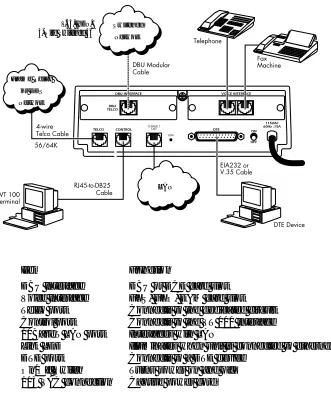
REAR PANEL
The Express 5210 is equipped with a DB-25 connector labeled DTE. Connections to the dedicated circuit and VT 100 interface are provided through the 8-pin telco jacks labeled TELCO and
Chapter 2. Installation
CONTROL, respectively. A 10BaseT LAN port is also provided. Pin assignments for these connectors are given in the appendix Pinouts on page A-1. The Express 5210 rear panel is shown in Figure 2-1.
Figure 2-1. Express 5210 Rear View
Item Function
DBU Interface Voice Interface Telco port Control port 10BaseT LAN port Link LED
DTE port On/Off Switch 115 VAC connection
DBU or DCE card slot FXS, FXO, E&M card slot Connects to the dedicated circuit Connects to the VT 100 interface Interfaces with LAN
Illuminates when unit is connected to ethernet hub Connects to a DTE device
Turns power on and off Captive power cord
LAN Frame Relay
or DDS
Network
V.34, ISDN, 4-Wire Switched 56
Switched
Chapter 2. Installation
2-4 Express 5210 User Manual 61200208L1-1
DBU and Voice Interface Card Slots
The Express 5210 rear panel has two card slots for the installation of dial backup, voice, and DCE interface cards. To insert cards, perform the following procedure:
1. Remove power from the Express 5210 (the cards are not hot-swappable).
2. Slide the card into the corresponding rear slot until the card panel is flush with the Express 5210 chassis.
3. Push card locks in (until they click) to secure the card and ensure proper installation.
Telco Connector
The TELCO connector is an eight-position modular jack which provides connection to a dedicated 56/64 kbps network. See Table A-1 in the Pinouts appendix for the TELCO connector's pin
assignments.
Control Port
The eight-position modular jack labeled CONTROL provides connection to a VT 100 EIA-232 compatible interface. This enables the Express 5210 to be configured through a terminal instead of the front panel. Use the VT 100 terminal cable (provided) for this connection. See Table A-2 in the Pinouts appendix for the connector pin assignments. A description of the operation of this port is covered in the section VT 100 Terminal Connection and Operation on page 3-2.
Chapter 2. Installation
10BaseT LAN Connector
The LAN port is an 8-pin modular connector that provides a 10BaseT ethernet LAN interface. This interface is used for SNMP and TELNET management and can also route non-management data to any of the IP addresses known to the Express 5210. When illuminated, the Link LED (located on the rear panel) indicates proper connection to a 10BaseT hub. The pin assignments for this connector are listed in Table A-3 of the appendix Pinouts.
DTE Connectors
Connect a DTE device to the DTE connector using either an EIA-232 DTE cable or an ADTRAN V.35 DTE adapter cable. The maximum cable lengths recommended are 50 feet for the EIA-232 and 100 feet for the V.35. The pin assignments are listed in Table A-4 of the appendix Pinouts.
The V.35 adapter cable is recommended for use with data rates above 19.2 kbps. A low capacitance EIA-232 cable works up to 56 kbps. The DTE port is configured through the front panel or the VT 100 control port and can operate in asynchronous or
Chapter 2. Installation
Chapter 3
Menu Navigation
The Express 5210 can be configured using the front panel, terminal interface, or a TELNET session. IP routing functions, statistical information, testing options, and dialing functions are also accessible from all interfaces; however, the terminal and TELNET menu interfaces offer a more detailed menu structure.
This chapter explains the terminal and front panel methods of operation. TELNET operation is similar to the terminal operation. The terminal interface description follows, and the front panel interface description begins on page 3-9. An overview of the menu structure (which corresponds with the remaining chapters of this manual) is presented on page 3-12. Information on setting up VT 100 and TELNET sessions is presented in the chapter Using the
Utilities Disks on page 4-1.
TERMINAL INTERFACE
Chapter 3. Menu Navigation
3-2 Express 5210 User Manual 61200208L1-1
VT 100 Terminal Connection and Operation
To control the Express 5210 using a VT 100 terminal, perform the following procedure:
1. Set the Express 5210 baud rate to match the terminal through the front panel (default rate is 9600 bps). Select 1CONFIG, then CONTROL PORT.
2. Using the provided VT 100 terminal adapter cable, connect the COM port of a VT 100 compatible terminal or equivalent to the eight-pin modular jack labeled CONTROL on the rear of the Express 5210. This connection is used for both local and remote configuration.
3. Open the connection and press the terminal keyboard's Enter key repeatedly until the first menu appears.
4. Pressing any key selects LOCAL LOGIN, which is used to configure the Express 5210 unit connected to the terminal. Pressing ^R (Ctrl R) selects REMOTE LOGIN, which is used to configure a remotely located Express 5210 unit. For remote applications, enter the DLCI (data link connection identifier) of the remote unit at the prompt. Then press Enter.
5. Enter the password. The factory default password is adtran (all lower-case). The main menu will appear, as shown in Figure 3-1.
In the lower left-hand corner of the terminal screen, L, R,or T is dis-played, indicating the type of interface the current screen represents (lo-cal, remote, or TELNET).
Chapter 3. Menu Navigation
Terminal Menu Navigation
The Express 5210 uses a multilevel menu structure that contains both menu items and data fields. All menu items and data fields dis-play in the terminal menu window, through which you have com-plete control of the Express 5210. The callouts in Figure 3-1 illustrate the terminal menu layout. The sections following the figure de-scribe each callout.
Figure 3-1. Top-level Terminal Menu Window
Menu Path
The first line of the terminal menu window (the menu path) shows the session’s current position in the menu structure. For example, Figure 3-1 shows the top-level menu with the cursor on the CONFIGURATION submenu; therefore, the menu path reads EXPRESS
5210/CONFIGURATION. Left Pane
Right Pane Menu Path
DBU Status
Signaling Status Navigation Help
Chapter 3. Menu Navigation
3-4 Express 5210 User Manual 61200208L1-1
Left and Right Window Panes
When you first start a terminal menu session, the terminal menu window is divided into left and right panes. The left pane shows the list of available submenus, while the right pane shows the contents of the currently selected submenu.
Window Pane Navigation
Use the following chart to assist you in moving between and within the two window panes.
To move... Press one of these keys...
From left pane to right pane Tab Enter Right arrow
From right pane to left pane Tab Escape Left arrow
Within each pane Up arrow
Chapter 3. Menu Navigation
Right Window Pane Notation
The right window pane shows the contents of the currently selected menu. These contents can include both submenu items and data fields. The following chart explains the notation used to identify these items.
l
Additional Terminal Menu Window Features This notation... Means that...
[data] More items are available when selected.
<data> An action is to be taken, such as activating a test. Menu item is
highlighted when scrolled to
You can enter data in this field.
Menu item is underlined when scrolled to
The field contains read-only information.
Login Type Displays L when menu reflects the local unit, R for a re-mote unit, and T during a telnet session.
System Name Displays the name entered in the SYSTEM NAME field
(see page 11-3).
DSU Status Displays the current state of the incoming network cir-cuit.
Signaling Status Displays the current LMI state of the network interface. DBU Status Displays the current state of the DBU service (available
when a DBU card is installed).
Chapter 3. Menu Navigation
3-6 Express 5210 User Manual 61200208L1-1
Navigating Using the Keyboard Keys
You can use various keystrokes to move through the terminal menu, to manage a terminal menu session, and to configure the system. Press Ctrl-Z to activate a pop-up screen listing the navigation key-strokes.
Moving through the Menus
To do this... Press this key...
Return to the home screen. H
Jump between two menu items.
Press J while the cursor is located on a menu item, and you jump back to the main screen.
Go to another menu item, press J, and you jump back to the screen that was displayed the first time you pressed J. Press J anytime you want to jump between these items.
J
Highlight items. Arrows
Select a highlighted menu item or descend one menu level. Enter
Cancel an edit. Escape
Close pop-up help screen. Escape
Move between the left and right panes. Tab
Arrows
Move to the top of a screen. A
Move to the bottom of a screen. Z
Chapter 3. Menu Navigation
Session Management Keystrokes
Configuration Keystrokes
To do this... Press this...
Log out of a session. Ctrl-L
Invalidate the password entry and return to the login screen. Ctrl-S Refresh the screen.
During normal operation, only the portion of the screen that has changed is refreshed. This option should only be necessary if the display picks up incorrect characters.
Ctrl-R
To do this... Press this key...
Restore factory default settings.
When in the IP SETUP menu, this setting restores the factory defaults based on the location of the cursor.
F
Copy selected items to the clipboard.
The amount of information you can copy depends on the cursor location when you press C:
• If the cursor is over an editable field, only that item is copied. • If the cursor is over the index number of a list, then all of the
items in the row of the list are copied.
C
Paste the item stored in the clipboard, if the information is compatible.
You must confirm all pastes—except those to a single editable field.
P
Increment the value of certain types of fields by one when you paste information into those fields.
Chapter 3. Menu Navigation
3-8 Express 5210 User Manual 61200208L1-1
Decrement the value of certain types of fields by one when you paste information into those fields.
<
Insert a new list item.
For example, add a new item to the ADDRESS TABLE by pressing I while the cursor is over the index number.
I
Delete a list item.
For example, delete an item from the ADDRESS TABLE by
pressing D while the index number is active.
D
Chapter 3. Menu Navigation
FRONT PANEL INTERFACE
The Express 5210 front panel (shown in Figure 3-3 on page 3-15) uses a multilevel menu structure containing both configurable menu items and read-only data fields. Information is displayed in the LCD window. Use the following chart to assist you in using the front panel interface.
To do this... Press this...
Activate a menu item (see the following note) Arrow Keys
Select an active (flashing) menu item Enter
Stop the current activity and return to the previous menu Cancel Select menu items or enter numeric information Number Keys
Edit the next entry in a routing table Shift-Next
Edit the previous entry of a routing table Shift-Prev
Add an entry to a routing table Shift-Add
Delete the displayed routing table entry Shift-Delete
Chapter 3. Menu Navigation
3-10 Express 5210 User Manual 61200208L1-1
LED Descriptions
The Express 5210 front panel has seven LED indicators: TD, RD, ETH, TDN, RDN, ALM, and TST. These LEDs are identified as follows:
Possible Alarm Conditions
DDS Alarm Conditions • Open loop on network • No frame synchronization • OOS/OOF
Frame Relay Alarm Condition
• Network frame relay signaling state down LED This LED is active when...
TD the DTE port is transmitting data. RD the DTE port is receiving data.
ETH the 10BaseTLAN port is transmitting or receiving data. TDN the network port is transmitting data.
RDN the network port is receiving data.
ALM an alarm condition exists. Alarm conditions are described in the section following this table.
Chapter 3. Menu Navigation
Front Panel Operation Example
The following steps and Figure 3-2 illustrate how to select Express 5210 options:
1. Activate CONFIGURATION (CONFIG) by using the arrow keys or pressing 1. The cursor will flash on the number next to the activated selection. Press Enter.
2. Use the arrow keys to view submenu items. 3. Choose an item on the submenu such as DTE PORT.
4. Activate DTE PORT by using the arrow keys or pressing 1. Press Enter.
5. Activate PROTOCOL options by using the arrow keys or pressing 1. Press Enter.
6. Press the arrow keys until the desired protocol is displayed. Press Enter.
Figure 3-2. Example of Front Panel Navigation DISABLE
FRAME RELAY
DTE PORT PROTOCOL SDLC
CONFIG FXS/FXO/E&M OPTIONS PHYS LYR OPTS TRANS BOP
NETWORK PORT PROTOCOL OPTS TRANS ASYNC
DIAL BACKUP ADDR TABLE PPP SYNC
CONTROL PORT PPP ASYNC
Chapter 3. Menu Navigation
3-12 Express 5210 User Manual 61200208L1-1
EXPRESS 5210 MENU STRUCTURE
The menu structure for both the terminal and front panel interfaces are basically the same. The opening menu is the access point to all other operations and each MAIN menu item leads to functions and submenus which identify and access specific parameters. The following table describes the menu structure and references the corresponding chapters.
Main Menu Item
Description For More Information
Configuration Sets network operating parameters for the DTE, voice, network, and dial backup interfaces. Also provisions system options.
Overview: page 6-1 DTE Port: page 7-1 Voice Cards: page 8-1 Network Port: page 9-1 Dial Backup: page 10-1 System: page 11-1 IP Setup Sets IP routing tables and displays
read-only routing information.
See page 12-1. View Statistics Displays status information for the
DTE port, network port, ethernet port, DBU cards, protocol, system, and the voice cards.
See page 13-1.
Test Activates voice tests and PVC loop-back testing functions.
See page 14-1. Dial Provides access to dialing functions
(only available when DBU card is in-stalled).
See page 15-1.
Voice testing is only available when a voice card is installed.
Chapter 3. Menu Navigation
When DTE PORT is selected, the PROTOCOL enabled determines the se-lections for PHYSICAL LAYER OPTIONS, PROTOCOL OPTIONS, and AD
-DRESS TABLE. See the chapter DTE Port Configuration on page 7-1 for more information.
Chapter 3. Menu Navigation
Chapter 4
Using the Utilities Disks
OVERVIEW
ADTRAN delivers PC software utilities with the Express 5210. These utilities are located on the three diskettes that came with your shipment. They also include MIB files (located in the MIB directory).
The utilities make setting up TELNET sessions and interfacing with the terminal menus easier. The utilities all run on Microsoft Windows 3.1 or higher. The following sections describe the TELNET and VT 100 utilities.
TELNET UTILITY
The TELNET utility delivered with the Express 5210 provides enhancements to standard TELNET programs that make it easier to work with Express 5210 options.
The TELNET menus include SESSION, EDIT, OPTIONS, CAPTURE,
and HELP (see the menu tree in Figure 4-1 on page 4-2).
Review the readme file (Readme.txt) for the latest information about the utilities.
Chapter 4. Using the Utilities Disks
4-2 Express 5210 User Manual 61200208L1-1
Figure 4-1. TELNET Menu Tree
Session Menu
Click on SESSION to open the TELNET session.
Connect
Opens dialog box for setting HOST NAME and PORT parameters for a
TELNET session. Also lets you EDIT ENTRY, ADD NEW entry, and
DELETE stored entries. When the parameters are set, click CONNECT
to make the connection. Click CANCEL to end the session.
Host Name
Connect Port
Session Disconnect Edit Entry Transfer Cfg Add New
Exit Delete
Connect
Edit Copy
Paste
Background
Telnet Options Colors Bold
Local Echo Text Auto Repeat
Capture Buffer Size Save Buffer As Screen Capture
Chapter 4. Using the Utilities Disks
Host Name
Accepts and stores host names. You may enter a name, an IP address, or a domain name directly into this field. Click on the drop-down arrow to display a complete list of previously stored host names.
Port
Provides several port options. You may enter port numbers directly into this field to connect to non-standard ports, or you may select the drop-down combo-box to display the following options:
Edit Entry
Changes either the unit name or the IP address of each host. Press either Tab, Return,or a period(.) after each number in the IP address to move to the next field. If you press Return or (.) while the cursor is located in each IP field, that field entry is deleted.
Add New
Prompts you for the same information as the EDIT ENTRYdialog
box for a new host. When enabled, the USE DNS (domain name
server) feature allows users to request DOMAIN LOOK UP via a DNS
server on the network, rather than specifying an IP address. The name then appears in the HOST NAMEfield.
Delete
Removes a host name from the list; simply select the host name you want to remove and, at the prompt, click DELETE.
Connect
Establishes the TELNET session.
TELNET Establishes a TELNET session
ECHO Provides a loopback for troubleshooting DISCARD Bit bucket; discards data
DAYTIME Returns the time
Chapter 4. Using the Utilities Disks
4-4 Express 5210 User Manual 61200208L1-1
Disconnect
Terminates the TELNET session.
To re-establish the session, select CONNECT from the SESSIONmenu
or press ENTER three times. This action restores the previous
connection. Transfer Cfg
This feature is used primarily for sending configuration files to the unit.
Exit
Ends the TELNET session and closes the TELNET screen.
Edit Menu
Provides COPY and PASTE commands.
Options Menu
Provides viewing alternatives for the terminal screen. Colors
This option changes the color of the background window (BACKGROUND), bold highlights (BOLD), and text (TEXT). Local Echo
Echoes each character that you enter. AutoRepeat
Repeats characters you select from the keyboard if you hold down the key.
Capture Menu
Chapter 4. Using the Utilities Disks
Buffer Size
Disables terminal window scroll bars when set to zero. (This is the normal setting for the Express 5210.) This number represents the number of lines to capture in the memory buffer.
Save Buffer As
Saves screen capture to a file. Screen Capture
Copies the text on the current TELNET screen to the clipboard. You can open any word processor and paste the clipboard contents into the program. This option is helpful when debugging.
Help Menu
Provides on-line help for using the ADTRAN Utilities. Contents
Opens the on-line help. IP Status
Displays the local port address and the status of the connection. About
Displays version and owner information.
VT 100 UTILITY
Chapter 4. Using the Utilities Disks
4-6 Express 5210 User Manual 61200208L1-1
Figure 4-2. VT 100 Utilities Menu Tree
Session Menu
Opens VT 100 terminal emulation session. Connect
Opens the specified serial port for a VT 100 session. Connect
Session Disconnect File Transfer Exit
Edit Copy
Paste
Port Settings
Refresh Screen Transmit Wakeup Connect Transmit Refresh VT 100 Options
Colors BackGround
Local Echo Bold Auto Repeat Text
File Start Cfg Capture
Capture Buffer Size Stop Cfg Capture Save Buffer As
Screen Capture
Chapter 4. Using the Utilities Disks
Disconnect
Closes the specified serial port at the end of a VT 100 session. File Transfer
This portion of the menu does not apply to this product.
Edit Menu
Identical to the TELNET EDIT MENU(see Edit Menu on page 4-4).
Port Menu
Changes serial COM port SETTINGS. Provides data rate settings from 300-57600 bps.
Options Menu
Provides terminal screen commands. Refresh Screen
Redraws the screen. Connect
Provides the options TRANSMIT WAKEUP and TRANSMIT REFRESH. Transmit Wakeup
Provides a control sequence that puts the Express 5210 Control port on-line in terminal mode.
Transmit Refresh
Provides a control sequence to automatically refresh the screen when connecting. This is the default setting for the Express 5210. Colors
Chapter 4. Using the Utilities Disks
4-8 Express 5210 User Manual 61200208L1-1
Local Echo
Echoes each character that you enter. AutoRepeat
Repeats characters you select from the keyboard if you hold down the key.
Capture Menu
Identical to the TELNET CAPTURE MENU (see Capture Menu on page 4-4).
Help Menu
Provides on-line help and information about the version number. Contents
Opens on-line help. About
Chapter 5
Applications
This chapter provides examples of some common Express 5210 data and voice applications. The data examples include SNA/ SDLC with local spoofing, transparent, and LAN applications. The voice applications (which begin on page 5-9) include switched, daisy-chaining, PLAR circuits, and direct FXS/FXO. The configuration selections given in these examples may need modification based on your network configuration.
DATA APPLICATIONS
SNA/SDLC with Local Spoofing
Chapter 5. Applications
5-2 Express 5210 User Manual 61200208L1-1
Different roles can be assumed for each SDLC session. Disconnec-tion starts the role determinaDisconnec-tion procedure again.
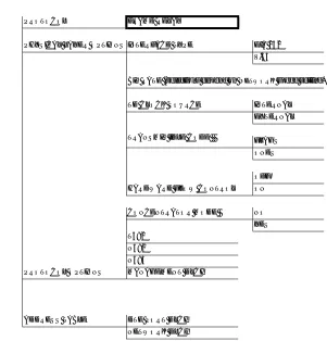
The Express 5210 uses LLC protocol (mode 2) to transport SDLC information frames. This protocol ensures a reliable link across frame relay, providing protection from frame loss and excessive delays. The encapsulation method uses the RFC 1490 format. See Table 5-1 for an example of how to configure the Express 5210 for this application.
Chapter 5. Applications
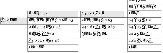
Table 5-1. SNA/SDLC Application Configuration Settings
HOST 5210 REMOTE 5210
DTE Port
Protocol SDLC SDLC
Physical Layer INTERFACE TYPE=EIA-232 INTERFACE TYPE=EIA-232
Options BIT RATE=19.2K BIT RATE=19.2K
TD CLOCK SOURCE=INTERNAL TD CLOCK SOURCE=INTERNAL TRANSMIT IDLE CODE=FLAGS TRANSMIT IDLE CODE=FLAGS
Protocol POLL/RESPONSE TIMEOUT=3 POLL/RESPONSE TIMEOUT=3
Options MINIMUM POLL TIMER=0 MINIMUM POLL TIMER=0 SLOW POLL RATIO=1 SLOW POLL RATIO=1
DISCONNECT THRESHOLD=10 DISCONNECT THRESHOLD=10 TRANSMIT DELAY=0 TRANSMIT DELAY=0
CTS OPTION=FOLLOW RTS CTS OPTION=FOLLOW RTS DATA FORMAT=NRZI DATA FORMAT=NRZI
Address Table ENTRY #1 ENTRY #1
PU ADDRESS=C0 PU ADDRESS=C0 GROUP ADDRESS=0 GROUP ADDRESS=0 LLC2 SSAP=04 LLC2 SSAP=04 LLC2 DSAP=04 LLC2 DSAP=04 OUTGOING DLCI=120 OUTGOING DLCI=17
Network Port
Physical Layer LOOP RATE=64K LOOP RATE=64K
Options CLOCK SOURCE=FROM NTWK CLOCK SOURCE=FROM NTWK
Frame Relay SIGNAL TYPE=ANSI T1.617-D SIGNAL TYPE=ANSI T1.617-D
Options T391=10 T391=10
N391=6 N391=6
N392=3 N392=3
N393=4 N393=4
Chapter 5. Applications
5-4 Express 5210 User Manual 61200208L1-1
Transparent Application
In cases when the user protocol is not supported by the
Express 5210, the transparent mode may be used. Transparent bit-oriented protocol (BOP) or transparent asynchronous protocol may be selected. This can be used for point-to-point connections only because the Express 5210 is transparent to the protocol address formats.
In the TRANSPARENT BOP protocol, the Express 5210 accepts an HDLC-like protocol and encapsulates the information field of the HDLC frames, transporting them across the frame relay network to the specified virtual circuit and remote Express 5210 port number. The incoming frames must be spaced with at least one flag byte (0x7E) and contain two bytes of CRC16 at the end of each frame. Asynchronous protocols are supported by using the TRANSPARENT
ASYNC mode. The Express 5210 buffers async characters and encapsulates the data portion of each character for transport across frame relay using a programmable DLCI and remote Express 5210 port number.
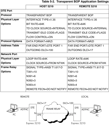
See Figure 5-2 and Table 5-2 for an example of a transparent BOP configuration. See Figure 5-3 and Table 5-3 for an example of a transparent asynchronous application.
Chapter 5. Applications
Table 5-2. Transparent BOP Application Settings
Figure 5-3. Transparent Async Application
HOST 5210 REMOTE 5210
DTE Port
Protocol TRANSPARENT BOP TRANSPARENT BOP
Physical Layer INTERFACE TYPE=V.35 INTERFACE TYPE=V.35
Options BIT RATE=64K BIT RATE=64K
TD CLOCK SOURCE=INTERNAL TD CLOCK SOURCE=INTERNAL TRANSMIT IDLE CODE=FLAGS TRANSMIT IDLE CODE=FLAGS FLOW CONTROL=ON FLOW CONTROL=ON
Protocol Options DATA FORMAT=NRZI DATA FORMAT=NRZI
Address Table FAR END PORT=DTE PORT 1 FAR END PORT=DTE PORT 1 OUTGOING DLCI=100 OUTGOING DLCI=17
Network Port
Physical Layer LOOP RATE=64K LOOP RATE=64K
Options CLOCK SOURCE=FROM NTWK CLOCK SOURCE=FROM NTWK
Frame Relay SIGNAL TYPE=ANSI T1.617-D SIGNAL TYPE=ANSI T1.617-D
Options T391=10 T391=10
N391=6 N391=6
N392=3 N392=3
N393=4 N393=4
Chapter 5. Applications
5-6 Express 5210 User Manual 61200208L1-1
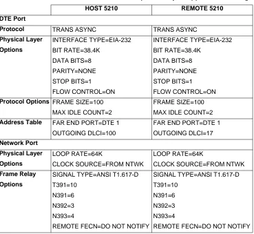
Table 5-3. Transparent Async Application Settings
HOST 5210 REMOTE 5210
DTE Port
Protocol TRANS ASYNC TRANS ASYNC
Physical Layer INTERFACE TYPE=EIA-232 INTERFACE TYPE=EIA-232
Options BIT RATE=38.4K BIT RATE=38.4K DATA BITS=8 DATA BITS=8 PARITY=NONE PARITY=NONE STOP BITS=1 STOP BITS=1
FLOW CONTROL=ON FLOW CONTROL=ON
Protocol Options FRAME SIZE=100 FRAME SIZE=100 MAX IDLE COUNT=2 MAX IDLE COUNT=2
Address Table FAR END PORT=DTE 1 FAR END PORT=DTE 1 OUTGOING DLCI=100 OUTGOING DLCI=17
Network Port
Physical Layer LOOP RATE=64K LOOP RATE=64K
Options CLOCK SOURCE=FROM NTWK CLOCK SOURCE=FROM NTWK
Frame Relay SIGNAL TYPE=ANSI T1.617-D SIGNAL TYPE=ANSI T1.617-D
Options T391=10 T391=10
N391=6 N391=6
N392=3 N392=3
N393=4 N393=4
Chapter 5. Applications
LAN Application
The Express 5210’s 10BaseT ethernet port allows IP routing between the ethernet interface and other IP interfaces visible to the unit. TELNET management and SNMP management are also available via the ethernet interface.
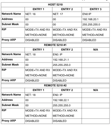
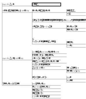
WAN interfaces may be numbered or unnumbered. Figure 5-4 depicts a numbered WAN interface. For purposes of this example, assume a subnet mask of 255.255.255.0. Routes to the remote LANs are established using static routes or RIP. Routes to the remote WAN interfaces are established using static routes, inverse ARP, or RIP. Once routes are established, IP traffic can flow between any two IP addresses shown in Figure 5-4. See Table 5-4 for an example configuration. The options listed in the table are found in the IP SETUP menu under INTERFACES.
Chapter 5. Applications
5-8 Express 5210 User Manual 61200208L1-1
Table 5-4. LAN Application Settings
HOST 5210
ENTRY 1 ENTRY 2 ENTRY 3
Network Name NET: 16 NET: 17 EN0:IP
Address 00 00 192.168.20.1
Subnet Mask 00 00 255.255.255.0
RIP MODE=TX AND RX MODE=TX AND RX MODE=TX AND RX METHOD=NONE METHOD=NONE METHOD=NONE
Proxy ARP DISABLED DISABLED DISABLED
REMOTE 5210 #1
ENTRY 1 ENTRY 2 N/A
Network Name NET: 18 EN0: IP
Address 00 192.168.21.1
Subnet Mask 00 255.255.255.0
RIP MODE=TX AND RX MODE=TX AND RX METHOD=NONE METHOD=NONE
Proxy ARP DISABLED DISABLED
REMOTE 5210 #2
ENTRY 1 ENTRY 2 N/A
Network Name NET: 18 EN0: IP
Address 00 192.168.22.1
Subnet Mask 00 255.255.255.0
RIP MODE=TX AND RX MODE=TX AND RX METHOD=NONE METHOD=NONE
Chapter 5. Applications
VOICE APPLICATIONS
Voice over frame relay can be accomplished using the Express 5210 with an optional dual voice card installed (Dual FXO, FXS, or E&M card). The following sections describe voice application examples using the Express 5210. Examples include switched mode (page 5-9), daisy-chaining (page 5-11), PLAR mode (page 5-12), and direct FXS/FXO (page 5-13).
Switched Mode Application
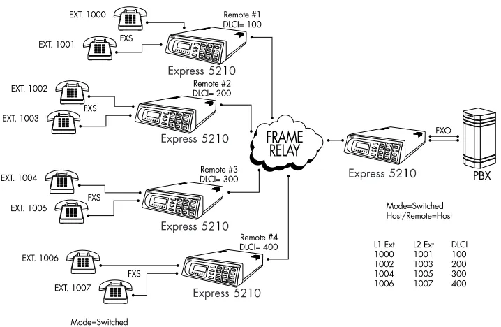
Switched mode is used to multiplex several remote extensions (up to 40) to two host ports (see Figure 5-5). This enables many remote users to have access to a limited number of access lines on a call-by-call basis. The host unit typicall-by-cally connects two extensions to a PBX via an FXO module. The remote units connect to telephone sets via FXS modules.
The host unit is programmed with the extensions and DLCI information for all of the remote units. This information is communicated to the remote units over the network. External Call Origination
When the telephone set on a remote Express 5210 is taken off-hook, the remote Express 5210 generates dial tone and waits for an extension to be entered by the user. Once the extension is entered, the remote Express 5210 transmits this information to the host Express 5210, where it is compared to extension information in the extension/DLCI table. If the extension is not located, the host assumes the number is external and attempts to seize an available port and dial the extension on the PBX. If no port is available, a trunk busy (fast busy) is returned to the remote port. After the extension is dialed, the data link is established and the call remains up until the remote Express 5210 terminates the call.
External Call Reception
Chapter 5. Applications
5-10 Express 5210 User Manual 61200208L1-1
are trying to reach. The host looks up the extension in the extension/DLCI table and routes the call appropriately. If the extension does not exist, the Express 5210 generates a trunk busy signal back into the PBX. Otherwise, the host routes the call to the appropriate port. When the remote party answers the call, the data link is established and the call remains up until the remote
Express 5210 hangs up or until a loss of line current is detected on the FXO port.
Internal Calls
Chapter 5. Applications
Figure 5-5. Switched Mode Application
Daisy-Chaining Over Frame Relay
Chapter 5. Applications
5-12 Express 5210 User Manual 61200208L1-1
Figure 5-6. Daisy-Chaining Application
PLAR Mode Application
PLAR (private line automatic ringdown) mode connects up to two remote telephone sets to one or two local telephone sets without a PBX. PLAR mode runs over a point-to-point DDS network or over a frame relay network. This mode requires the use of FXS modules on both ends for connection to the telephone sets. In PLAR mode, taking a phone off-hook rings the opposite end of the circuit. See Figure 5-7.
For PLAR mode, the DLCI for each voice port must be
Chapter 5. Applications
Figure 5-7. PLAR Mode Application
Direct Mode Application
Direct mode is used to set up a typical FXS/FXO extension
arrangement. In this mode, the local unit is connected to a PBX via an FXO module. The remote unit uses an FXS module to connect the telephone sets. In this arrangement, the local PBX extensions are extended across the frame relay or point-to-point DDS circuit. In direct mode, the Express 5210 is transparent to the telephone circuit. All signalling information is generated/detected by the attached PBX/telephone.
For direct mode, the DLCI for each voice port must be
Chapter 5. Applications
5-14 Express 5210 User Manual 61200208L1-1
Chapter 6
Configuration Overview
LOCAL AND REMOTE CONFIGURATION
The Express 5210 can be configured and managed locally and remotely. The unit supports multiple management sessions, allowing users to access configuration options simultaneously without interrupting each other’s activity.
Configuration Methods
The following configuration methods are supported:
• Configure a local Express 5210 using the front panel or a VT 100 interface.
• Configure a remote Express 5210 using a VT 100 REMOTE LOGIN
session established through a local unit. See the section
Terminal Interface on page 3-1 for information on selecting local
and remote configuration.
• Establish a TELNET session which allows you to control an Express 5210 through the terminal menus (see the section
TELNET Utility on page 4-1 for more information).
Chapter 6. Configuration Overview
6-2 Express 5210 User Manual 61200208L1-1
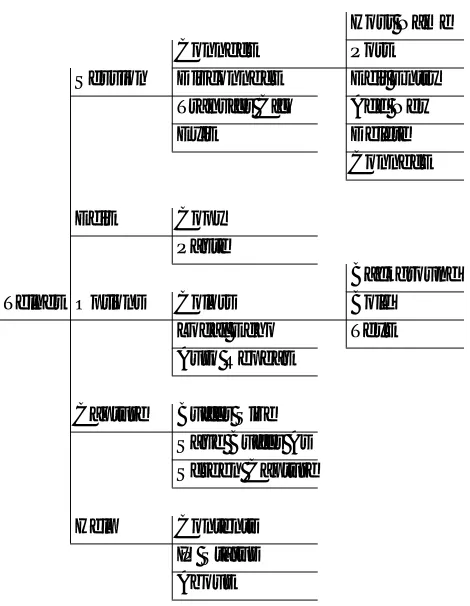
Configuration Menu
The CONFIGURATION menu (Figure 6-1) consists of submenus relating to specific interfaces or functions of the Express 5210 requiring setup:
DTE PORT
FXS/FXO/E&M OPTIONS (available when a voice card is installed) NETWORK PORT
DIAL BACKUP (available when a DBU card is installed) CONTROL PORT (front panel only)
SYSTEM
For detailed information on the individual branches of the CONFIGURATIONmenu, see the following chapters:
DTE Port Configuration on page 7-1 Voice Configuration on page 8-1 Network Port Configuration on page 9-1 Dial Backup Configuration on page 10-1 System Configuration on page 11-1
A CONFIGURATION menu tree is given in Figure 6-2 on page 6-5.
Configure the NETWORK PORT before the DTE PORT. Selections made will affect the choices available for the DTE PORT.
When configuring the DTE PORT, select the PROTOCOL first. This selec-tion determines which parameters will be available for the PHYSICAL
Chapter 6. Configuration Overview
.
Chapter 6. Configuration Overview
Chapter 7
DTE Port Configuration
Configure the PROTOCOL, PHYSICAL LAYER OPTIONS, PROTOCOL
OPTIONS, and ADDRESS TABLE for the DTE port located on the rear of the Express 5210 by selecting DTE PORTfrom the CONFIGURATION
menu. Figure 7-1 illustrates the terminal configuration menu for the DTE PORT.
Figure 7-1. DTE Port Configuration Menu Configure the NETWORK portbefore the DTE port. Selections made will affect the choices available for the DTE port.
Chapter 7. DTE Port Configuration
7-2 Express 5210 User Manual 61200208L1-1
See Figure 7-2 for the front panel menu tree leading to the
PROTOCOL selection. Definitions for each choice follow, categorized by the selected protocol.
Figure 7-2. Front Panel Protocol Menu Tree When configuring the DTE port, select the PROTOCOL first. This selec-tion determines which parameters will be available in the other three cat-egories (PHYSICAL LAYER OPTIONS, PROTOCOL OPTIONS, and ADDRESS TABLE).
In this chapter the terminal selections are listed first, followed by the front panel selections (if the names differ).
DISABLE FRAME RELAY
1 PROTOCOL SDLC
TRANS BOP 1 CONFIG 1 DTE PORT 2 PHYS LYR OPTS TRANS ASYNC
PPP SYNC 3 PROTOCOL OPTS PPP ASYNC
Chapter 7. DTE Port Configuration
Port Disabled Protocol (DISABLE)
Follow the menu tree shown in Figure 7-3 to disable the DTE PORT
PROTOCOL. If the DTE port is not in use, select PORT DISABLED. PHYSICAL LAYER, PROTOCOL, and ADDRESSTABLE options are not available when the port is disabled.
Figure 7-3. Port Disabled Menu Tree
Frame Relay Protocol
The FRAME RELAYprotocolis a synchronous protocol used to concentrate two different devices into a common frame relay link to the network. While configured for FRAME RELAYprotocol, the Express 5210 accepts frame relay frames from a router or a FRAD and routes to/from the network port based on the DLCI address. The address can be modified or preserved from the DTE and network side based on the frame relay address table. FECN, BECN, DE, and C/R states are not changed as frames are transferred between the DTE and the Telco ports. The menu tree in Figure 7-4 shows the choices available when the FRAME RELAYprotocol is selected.
Physical Layer Options (PHYS LYR OPTS)
Interface Type (INTERFACE)
Select the connector type for the DTE interface. The choices are EIA-232 and V.35. See Table A-4 in the appendix Pinouts for the connector pin assignments.
Bit Rate
Select the operating speed of the DTE interface.
CONFIG DTE PORT PROTOCOL PORT DISABLED
Chapter 7. DTE Port Configuration
7-4 Express 5210 User Manual 61200208L1-1
TD Clock Source (TD CLOCK SRC)
Set the clock source to INTERNAL or EXTERNAL. Transmit Idle Code (TX IDLE CODE)
Enable the Express 5210 to transmit FLAGS or all ONES. When
operating in FRAME RELAYprotocol, configure this option to
transmit FLAGS.
Hardware Flow Control
This option determines how the Express 5210 responds to congestion during DBU operation. The following chart explains the choices:
Off No flow control is used and the Express 5210 drops frames during severe congestion.
Chapter 7. DTE Port Configuration
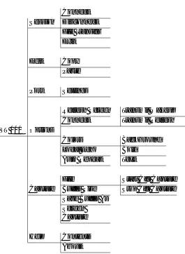
Figure 7-4. Frame Relay Protocol Menu Tree
Protocol Options (PROTOCOL OPTS)
Concentrator Mode (CON MODE)
When set to OFF, the Express 5210 inspects data for proprietary
traffic such as voice, remote configuration, and PVC loopback data. This allows frame relay and internally generated traffic (such as voice traffic) to travel the same DLCI.
T392
Set the timeout between polling intervals. This parameter needs to be a few seconds longer than the T391 setting of the attached frame relay device.
PROTOCOL FRAME RELAY
PHYSICAL LAYER OPTIONS INTERFACE TYPE EIA 232 V.35
BIT RATE (selections depend on NETWORK speed setting)
TD CLOCK SOURCE INTERNAL
EXTERNAL
TRANSMIT IDLE CODE FLAGS
ONES
OFF
HARDWARE FLOW CONTROL ON
CONCENTRATOR MODE NO
YES T392
N392
N393
PROTOCOL OPTIONS MANAGEMENT DLCI
ADDRESS TABLE DTE PORT DLCI
Chapter 7. DTE Port Configuration
7-6 Express 5210 User Manual 61200208L1-1
N392 and N393
T