ISSN (Print) : 2320 – 3765 ISSN (Online): 2278 – 8875
I
nternational
J
ournal of
A
dvanced
R
esearch in
E
lectrical,
E
lectronics and
I
nstrumentation
E
ngineering
(A High Impact Factor, Monthly, Peer Reviewed Journal)Website: www.ijareeie.com
Vol. 6, Issue 10, October 2017
Design of Low Complexity ASIC
Implementation of IFFT for MIMO OFDM
A.Laxmi Prasanna1, Dr.B.L.Malleswari2, B.Kavitha3
PG Scholar, Dept. of ECE, SWEC, Hyderabad, TS, India Principal & Professor, Dept. of ECE, SWEC, Hyderabad, TS, India
Assistant Professor, Dept. of ECE, Hyderabad, TS, India
ABSTRACT- This project mainly focuses on the realization of an efficient logic design of IFFT with projection techniques. A desirable properties of the VLSI circuits are the high speed operation. The use of IFFT design technique can provide high speed operation at lower silicon area requirement, compared to other CMOS designs. For increased data rates wireless transmission, OFDMs are widely used. OFDMs are merged with arrays of antenna at the tranx & the recx side to expand the system volume on frequency & time variant channels. Here we design MIMO OFDM in Matlab. The parallel IFFTs protected in this project by redundant module and parseval module. Here we consider IFFTs with length N=16. This project designed using ASIC Technology. IFFTs are designed for faster speed and less routing area with special units. The system is realised using verilog. Fault tolerance has applied to protect IFFTs proposed scheme that join the use of ECC & parseval checks. It is simulated using NC (Native code complier) of cadence and synthesized using RC (RTL code complier) of cadence tool. The physical layout is designed for arrangement of standard cells (PD-physical design) in cadence. This project results shows the preferred technique can additionally reduce the area, operating time and improves the error correction rates over wired or wireless communication systems.
KEYWORDS:- Error correction codes, IFFT, Parseval check, MIMO, OFDM.
I.INTRODUCTION
In communication and signal processing circuits difficulty increases every year. This is because of CMOS scaling technology that it includes addition of extra transistors on single chip. The increased complexity leads circuit more suspect to errors. In today’s technology as scaling expands soft errors also increases[1]. An error where given signal is wrong this can effect the system operation i.e. is called soft errors.
Soft errors are defined in two ways in signal processing they are chip level and system level. Chip level errors has been occurred when particles hits chip and when data being handle hits with noise, typically data on channel is system level errors[2]. The system is said to continue to run correctly in the event of non success of some of it’s components is done by fault tolerant[3]. Fourier transforms are captivating because of there best showing and throughput. Throughput is compared to system with fault tolerance. Parallel transformations (IFFTs) reduces computation time and improves performance by factor[4]. Signal is transferred when it is converted from 1 state to another state. The core architecture employee’s IFFT with ECC technique and SOS to achieve error free data, high speed and reduces the area as compared with existing system. This architecture is implemented in ASIC. By using the core architecture we are widely using it for MIMO OFDM for wireless technologies, power line networks, 4G mobile communications, audio broad casting. Here IFFT in MIMO OFDM is used as modulation[5]. Inter symbol and interference are two problems in today’s modern communication. Purpose of OFDM is to increase the quality of the signal is strong or not against the attenuation of a signal and narrow band interference. OFDM is arrogate as the modifying method in technologies like wireless because of bulky data delusion and loss of signal through channel. To defeat these complication we are designing[6] .
ISSN (Print) : 2320 – 3765 ISSN (Online): 2278 – 8875
I
nternational
J
ournal of
A
dvanced
R
esearch in
E
lectrical,
E
lectronics and
I
nstrumentation
E
ngineering
(A High Impact Factor, Monthly, Peer Reviewed Journal)Website: www.ijareeie.com
Vol. 6, Issue 10, October 2017
1.Fast Fourier Transform algorithm change the signal from time dominion to frequency dominion. It computes transformation through DFT computations. It is used in convolution of two signals .
2. Error tolerant technique for parallel transformations (IFFT) protects transformations from errors. In my work error
correction using hamming codes. Here error correction is based on encoder of hamming codes and decoder in order to get the required data with error free.
3. Fault tolerant technique based on Parseval’s checks is used to distinguish errors parallel in multiple IFFTs . Parseval check is the property used to define the power. It defines the power whether it is same in time state to frequency state or vice versa.
4. The transformations in parallel increases the range of error correction codes . Generating parity for parallel transformations also helps in diminish the entanglement in the ECC.
5. Here we are mainly concentrating on low complexity by reducing the complex multiplication in IFFTs the area will reduce and also power will be reduced.
II.PROPOSED PROTECTION SCHEME FOR PARALLEL FFTS
Many techniques or methods has been evolved to protect the FFTs. Sum ofSquare check is one of the technique that is
used to detect errors. The parseval theorem is based on SOS check that states in/pt to FFT are equivalent to the ot/pt of the FFTs. This is used to identify errors with little overheads as one multiplication is required for each input and output sample[9]. For parallel FFT, the ECC technique can combine with SOS check to reduce protection overhead. The SOS check alone can identify errors and the ECC will apply the correction this can be finished by equivalent parity bit for all FFTs. The parseval check is applied on FFTs to identify errors. When an error is identified, the out turn of the parity FFT is adjoin as the sum of inputs to the original FFT as input. Then parseval check is also connected to each real FFT.
Figure.1 Parallel ffts with parity-sos-ecc
If the error is detected using S1....S4 , the correction can be finished by FFT in error using the output of parity FFT(P) and the remaining outputs. For example if an error arise in the first FFT, s1 will be set and the error will be corrected by R1c=P-S2-S3-S4.
ISSN (Print) : 2320 – 3765 ISSN (Online): 2278 – 8875
I
nternational
J
ournal of
A
dvanced
R
esearch in
E
lectrical,
E
lectronics and
I
nstrumentation
E
ngineering
(A High Impact Factor, Monthly, Peer Reviewed Journal)Website: www.ijareeie.com
Vol. 6, Issue 10, October 2017
The in/pt & out/pt of FFT is given to the magnitude sum block. It compares the in/pt and ot/pt for verifying the FFT output. If input and output are equal then FFT is soft error Free. The parallel FFTs is nothing but parallel arrangement of FFTs to perform operation fast as compared with series arrangement of FFTs. Parellel FFTs with fault tolerant parity–SOS-ECC is implemented in FFT architecture which consists of Ram, selector, address generator, cordic, rotation Factor. If the cordic technique is applied for transformation then effects of FFT action will give efficient outcome and cordic provides sin and cosine terms to FFT in/pt bits[10]. The selector is nothing but memory track way buffer which evaluate respective memory for in/pt samples. When the active in/pt signal is assets & there was some in/pt data, the address generator blocks assign a memory position for each in/pt sample. Now when the twofold ram receives the write address signal from the address generator block, it will rescue both memory track way along with the in/pt samples.
Figure.3 FFT architecture implementation
When rotation factor and FFT block gets start signal, then FFT block sends information to the cordic generator for computing required twiddle factors consisting of sine & cosine terms Cordic is managed by rotation factor. Now when address block gets read signal to Ram, it sends in/pt Data samples along with memory track way in FFT block. The twiddle factors are appeal to the ot/pt of the butterflies and bit reverse samble is done[11]. The FFT and separate protection scheme techniques have implemented using verilog. The design system is mapped to ASIC for minimizing resources.
III. EXTENSION PROTECTION SCHEME FOR PARALLEL IFFTS ERROR CORRECTION & DETECTION ON HAMMING CODES
ISSN (Print) : 2320 – 3765 ISSN (Online): 2278 – 8875
I
nternational
J
ournal of
A
dvanced
R
esearch in
E
lectrical,
E
lectronics and
I
nstrumentation
E
ngineering
(A High Impact Factor, Monthly, Peer Reviewed Journal)Website: www.ijareeie.com
Vol. 6, Issue 10, October 2017
IFFTS PARALLEL WITH FAULT TOLERANT PARITY-SOS-ECC
Figure.7 IFFT parallel with fault tolerant parity-SOS-ECC
PARSEVAL CHECK IMPLEMENTATION
Figure.8 Parseval Check for IFFT implementation
IFFT ARCHITECTURE IMPLEMENTATION
Parellel IFFTs with fault tolerant parity–SOS-ECC is implemented in IFFT architecture which consists of Ram, selector, address generator, cordic, rotation Factor. If the cordic technique is applied for IFFT computation then properties of IFFT operation will give efficient result.
Fig.9 IFFT architecture Implementation
IV. APPLICATION FOR EXTENSION SYSTEM MIMO OFDM IMPLEMENTATION
ISSN (Print) : 2320 – 3765 ISSN (Online): 2278 – 8875
I
nternational
J
ournal of
A
dvanced
R
esearch in
E
lectrical,
E
lectronics and
I
nstrumentation
E
ngineering
(A High Impact Factor, Monthly, Peer Reviewed Journal)Website: www.ijareeie.com
Vol. 6, Issue 10, October 2017
Figure.10. Block diagram of MIMO OFDM Matlab Implementation
INTERNAL BLOCK DIAGRAM IMPLEMENTATION OF QPSK MODULATOR
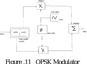
Figure .11 QPSK Modulator
In QPSK 2 sine curves i.e, sine & cos are consider as basic functions for modulation. Modulation is attained by alter the phase of basic function depending on the message symbols. QPSK modulation is symbol/data based where 1 symbol contains 2 bits. QPSK modulation the signal has two components i.e, in-phase & quadrature. Because it has 2 basic functions. Each of odd bits i.e quadrature arm & even bits i.e In-phase arm. The arm on In-phase signal was accumulated by cos component & the signal on quadrature arm was acumulated by sine component. QPSK modulated signal was acquired by joining the signal both In-phase & quadrature arm.The internal block diagram of IFFT in OFDM is implemented as my proposed work. In communication applications DFT is important unit for OFDM. DFT is a tool to act upon frequency analysis of discreate time signal. For discreate purpose DFT is continous fourier transform. For the input as real sequence, the DFT outputs them as complex sequence numbers. If the given input is real or compound, the model of adders and multipliers are fromed. If N-point DFT is applied, the arthimatic unit of order O(N2) i.e., N2 multiplications & N(N-1) additions.
INTERNAL BLOCK DIAGRAM IMPLEMENTATION OF QPSK DEMODULATOR
Figure.12 QPSK Demodulator
ISSN (Print) : 2320 – 3765 ISSN (Online): 2278 – 8875
I
nternational
J
ournal of
A
dvanced
R
esearch in
E
lectrical,
E
lectronics and
I
nstrumentation
E
ngineering
(A High Impact Factor, Monthly, Peer Reviewed Journal)Website: www.ijareeie.com
Vol. 6, Issue 10, October 2017
bits on in-phase arm & on quadrature arm were remapped to get detected message stream. FFT and IFFT used in OFDM to map digitally modulated in/pt data onto orthogonal alongside conveyor.
V. RESULTS
LOGICAL SIMULATION RESULTS
This logical simulation result shown into the Simulink block in Matlab 2014b.The Matlab 2014b is a user friendly software. Here the figure shows the mimo ofdm implementation.
Figure. 13 Matlab simulation result
In the above figure, the subsystems are designed and implemented through AISC.
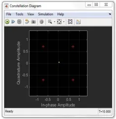
Figure.14 Simulation result for modulation.
ISSN (Print) : 2320 – 3765 ISSN (Online): 2278 – 8875
I
nternational
J
ournal of
A
dvanced
R
esearch in
E
lectrical,
E
lectronics and
I
nstrumentation
E
ngineering
(A High Impact Factor, Monthly, Peer Reviewed Journal)Website: www.ijareeie.com
Vol. 6, Issue 10, October 2017
MATLAB OF PROPOSED RESULT
Figure.16 . Matlab simulation result for FFT 16 proposed
In MATLAB arithmetic tool block mainly consists of Add/Sub, Mul and div blocks. Here we have designed a FFT by taking arithmetic blocks of 2 bit. By using this mathematical function, we generated a code.
Figure.17. Internal block implementation of above subsystem
MATLAB OF EXTENSION RESULT
ISSN (Print) : 2320 – 3765 ISSN (Online): 2278 – 8875
I
nternational
J
ournal of
A
dvanced
R
esearch in
E
lectrical,
E
lectronics and
I
nstrumentation
E
ngineering
(A High Impact Factor, Monthly, Peer Reviewed Journal)Website: www.ijareeie.com
Vol. 6, Issue 10, October 2017
Figure.19 Internal block implementation of above subsystem
NETLIST SIMULATION RESULT
Figure.20 Simulation in NC
ENCOUNTER (SYSTEM ON CHIP -SOC)
ISSN (Print) : 2320 – 3765 ISSN (Online): 2278 – 8875
I
nternational
J
ournal of
A
dvanced
R
esearch in
E
lectrical,
E
lectronics and
I
nstrumentation
E
ngineering
(A High Impact Factor, Monthly, Peer Reviewed Journal)Website: www.ijareeie.com
Vol. 6, Issue 10, October 2017
COMPARISON RESULTS
Table.1 Power Analysis in 180 nm technology
Sl.no Name of the system Leakage Power(nw) Dynamic Power(nw) Total Power(nw)
1. Proposed 1539.035 116954269.457 116955808.492
2. Extension
245.858
99933062.318
99933408.176
Table.2 Area Analysis of Proposed System
Sl.no Name of the
System
Technology Total Area
1. Proposed 180nm 293159
2. Extension 180nm 69103
From above tables, there is a decrease in area and power. ie., it consumes less area and low Power. And the Proposed & extension is done in 180nm technology. The Implementation is done in ASIC.
VI. CONCLUSION
This project proposed the ASIC implementation of the IFFT architecture for communication to get error free data i.e IFFTs are used in many signal processing applications. Here we used hamming encoder & decoder to detect & correct the data. This proposed work is done in 180nm technology. When comparing with the previous proposed background they have implemented in an FPGA technology. IFFTs are more efficient as compared to FFT. In IFFT the divide & conquer technique is implemented so operating time and signal processing time is less compared to FFT. In this proposed work protection against parallel IFFTS has implemented. The parseval check is utilized to detect & locate the errors & the parity IFFT is used for correction. The proposed technique was estimated both in terms of implementation complexity & error detection capabilities. The results reveals that the technique, which uses a parity IFFT and set of parseval’s checks that from an ECC, provides best results in terms of implementation complexity & error free data. This architecture can be used in many ofdm applications in real time environment.
VII.FUTURE SCOPE
There is a ultimate scope in this project as we can apply it for multi bit data rate faults based applications. The IFFT can further increases to higher bit rate i.e, 32. The design Instead of IFFT an DCT algorithm can be taken out in ASIC Implementation. SOS-ECC technique can detect and correct only single bit error, this can extended to mutli bit errors by using trillis code and further area can reduced as compared to IFFT. Here proposed work is done in 180nm technology. Further it can be implemented by DCT algorithm in 90 and 45nm technology in ASIC. So , the overall reliability of the system can increase with error free data.
REFERENCES
[1] R. Baumann, “Soft errors in advanced computer systems,” IEEE Des. Test Comput., vol. 22, no. 3, pp. 258–266, May/Jun. 2005.
ISSN (Print) : 2320 – 3765 ISSN (Online): 2278 – 8875
I
nternational
J
ournal of
A
dvanced
R
esearch in
E
lectrical,
E
lectronics and
I
nstrumentation
E
ngineering
(A High Impact Factor, Monthly, Peer Reviewed Journal)Website: www.ijareeie.com
Vol. 6, Issue 10, October 2017
[3] A. L. N. Reddy and P. Banerjee, “Algorithm-based fault detection for signal processing applications,” IEEE Trans. Comput., vol. 39, no. 10, pp.1304–1308, Oct. 1990.
[4] T. Hitana and A. K. Deb, “Bridging concurrent and non-concurrent error detection in FIR filters,” in Proc. Norchip Conf., Nov. 2004, pp.75–78.
[5] S. Pontarelli, G. C. Cardarilli, M. Re, and A. Salsano, “Totally fault tolerant RNS based FIR filters,” in Proc. 14th IEEE Int. On-Line Test Symp. (IOLTS), Jul. 2008, pp. 192–194.
[6] B. Shim and N. R. Shanbhag, “Energy-efficient soft error-tolerant digital signal processing,” IEEE Trans. Very Large Scale Integr. (VLSI) Syst., vol. 14, no. 4, pp. 336–348, Apr. 2006.
[7] E. P. Kim and N. R. Shanbhag, “Soft N-modular redundancy,” IEEE Trans. Comput., vol. 61, no. 3, pp. 323–336, Mar. 2012.
[8] J. Y. Jou and J. A. Abraham, “Fault-tolerant FFT networks,” IEEE Trans. Comput., vol. 37, no. 5, pp. 548–561, May 1988.
[9] S.-J. Wang and N. K. Jha, “Algorithm-based fault tolerance for FFT networks,” IEEE Trans. Comput., vol. 43, no. 7, pp. 849–854, Jul. 1994.
[10] G. L. Stüber, J. R. Barry, S. W. McLaughlin, Y. Li, M. A. Ingram, and T. G. Pratt, “Broadband MIMO-OFDM wireless communications,” Proc. IEEE, vol. 92, no. 2, pp. 271–294, Feb. 2004.
[11] P. Reviriego, S. Pontarelli, C. J. Bleakley, and J. A. Maestro, “Area efficient concurrent error detection and correction for parallel filters,” IET Electron. Lett., vol. 48, no. 20, pp. 1258–1260, Sep. 2012.
[12] Z. Gao et al., “Fault tolerant parallel filters based on error correction codes,” IEEE Trans. Very Large Scale Integr. (VLSI) Syst., vol. 23, no. 2, pp. 384–387, Feb. 2015.
[13] R. W. Hamming, “Error detecting and error correcting codes,” Bell Syst. Tech. J., vol. 29, no. 2, pp. 147–160, Apr. 1950.
[14] P. Reviriego, C. J. Bleakley, and J. A. Maestro, “A novel concurrent error detection technique for the fast Fourier transform,” in Proc. ISSC, Maynooth, Ireland, Jun. 2012, pp. 1–5.
BIOGRAPHY
Ms. A.Laxmi Prasanna has completed B.E in ECE Department from Sri Sai Jyothi Engineering college, Gandipet, Hyderabad. Presently pursuing Masters in VLSI System Design in Sridevi
Women‟s Engineering College, Vattina-gulapally, Gandipet, Hyderabad, India.
Dr.B.L.Malleswari working as professor and Principal in Sridevi Women’s Engineering college. She has got 80 National and International Conferences. Also 40 National and international publications. She is specialized in communications and GPS.