A New Guess-and-Determine Attack on the
A5/1
Stream Cipher
Jay Shah and Ayan Mahalanobis
Indian Institute of Science Education and Research, Pune, India jayshah [email protected]; [email protected]
Abstract. In Europe and North America, the most widely used stream cipher to ensure privacy and confidentiality of conversations in GSM mobile phones is theA5/1. In this paper, we present a new attack on theA5/1 stream cipher with an average time complexity of 248.5, which is much less than the brute-force attack with a complexity of 264. The attack has a 100% success rate and requires about 5.65GB storage. We provide a detailed description of our new attack along with its implementation and results.
Keywords:A5/1, GSM, guess-and-determine attack, stream ciphers
1
Introduction
The most widely used stream cipher to ensure privacy and confidentiality of conversations in GSM mobile phones in Europe and North America is theA5/1. TheA5/1 was developed in 1987, then GSM was not considered for use outside Europe. The description of theA5/1 was initially kept secret, but its design was disclosed in 1999 by reverse engineering [6]. The GSM organization later confirmed the correctness of the algorithm [5].
There are multiple versions of the encryption algorithm which belong to theA5 family: A5/0 is a dummy cipher with no encryption;A5/1 is the originalA5algorithm ensures over-the-air communication privacy and confidentiality of conversations in GSM mobile phones; A5/2 is an intentionally weaker encryption algorithm created for export; while A5/3 is a strong encryption algorithm created as part of the 3rd Generation Partnership Project (3GPP)which is currently responsible for maintaining and developing GSM technical spec-ifications around the world [12].
Anderson [1], Golic [11] and Babbage [2] were the pioneers in cryptanalyzing theA5/1 encryption algorithm when only a rough outline of theA5/1 was leaked. After A5/1 was reverse engineered, it was analyzed by Biryukov, Shamir and Wagner [5]; Biham and Dunkel-man [4]; Ekdahl and Johansson [8]; Maximov, Johansson and Babbage [15]; Barkan and Biham [3]; Keller and Seitz [13]; and a few other researchers.
1.1 Current Research
the same key is used regardless of whether the phone encrypts using A5/1,A5/2, orA5/3 algorithm. Therefore, the attacker can mount a man-in-the-middle attack, in which the attacker impersonates the mobile to the network, and the network to the mobile (by using a fake base station). The attacker might useA5/1 for communication with the network and A5/2 for communication with the mobile. But due to the flaw, both algorithms encrypt using the same key. The attacker can obtain the key through a passive attack onA5/2. The attacker who is in the middle can eavesdrop, change the conversation, perform call theft, etc. The attack applies to all traffic including short message service (SMS) [3].
1.2 Our Contributions
In this paper we describe a newguess-and-determineattack on theA5/1 stream cipher. This attack has an average time complexity of 248.5, which is much less than a brute-force attack of 264. For everypossible19 bits of the registerR
1, we require storage of 100MB to determine registers R2 and R3 given a known keystream KS. Our attack can be briefly described as follows: we assume that the registerR1 is full with 19 bits and registersR2 and R3 will be filled progressively as the attack progresses. At any stage of this attack, R1 is completely filled and R2 and R3 are partially filled. We call these states as state candidates. Once all three registers are completely filled, we call that state candidate a complete state candidate. This attack has a 100% success rate and requires about 5.65GB storage. With the knowledge of only 11 bits of the known keystream, the attack algorithm is able to determine a set of 64-bit complete state candidates which may contain the key. With every additional clocking round of the attack, the number of complete state candidates increases. Thus, the probability of finding the key among all the complete state candidates increases with every additional round after 11 clocking rounds. We provide a detailed description of our new attack along with its implementation and results in Sections 4, 5 and 6.
2
Description of the
A5/1
Stream Cipher
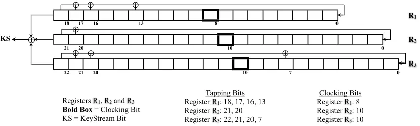
⊕
⊕
⊕
R3
KS
0
0
0
21 18
20
22 21
Registers R1, R2 and R3 Bold Box= Clocking Bit KS = KeyStream Bit
R1
R2 17 16 13
20 7
⊕ ⊕
⊕ ⊕
⊕
8
10
10
Tapping Bits Register R1: 18, 17, 16, 13 Register R2: 21, 20 Register R3: 22, 21, 20, 7
Clocking Bits Register R1: 8 Register R2: 10 Register R3: 10
TheA5/1 stream cipher is built from three short linear feedback shift registers (LFSRs) of lengths 19, 22, and 23 bits, denoted byR1,R2andR3respectively. The rightmost bit in each register is labeled as bit zero. The tapping bits of R1 are at bit positions 13, 16, 17, 18; the tapping bits ofR2 are at bit positions 20, 21; and the tapping bits ofR3 are at bit positions 7, 20, 21, 22 (Table 1).
Table 1.TheA5/1 Register Parameters
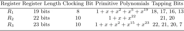
Register Register Length Clocking Bit Primitive Polynomials Tapping Bits
R1 19 bits 8 1 +x+x2+x5+x19 18, 17, 16, 13
R2 22 bits 10 1 +x+x22 21, 20
R3 23 bits 10 1 +x+x2+x15+x23 22, 21, 20, 7
The tapping bits are predetermined according to the corresponding primitive polynomials for the registers. A polynomial of degreenover the finite fieldGF(2) (i.e., with coefficients either 0 or 1) is primitive if it has polynomial order 2n−1. For each register, when the register is clocked, its tapping bits are XORed together and the result is stored in the rightmost bit of the left-shifted register. The three registers are maximal length LFSRs with periods 219−1, 222−1, and 223−1 respectively [14].
TheA5/1 keystream generator works as follows [6]. First, an initialization phase is run. At the start of this phase, all bits of the registers are set to 0. Then the key setup and theInitialization Vector (IV)setup are performed. During the initialization phase, all three registers are clocked and the key bits followed by the IV bits are XORed with the most significant bits (MSBs) of all three registers. Thus, the initialization phase takes an overall of 64 + 22 = 86 clock-cycles after which initial stateSi is achieved.
Based on this initial state Si, a warm-up phase is performed where the generator is clocked for 100 clock-cycles and the output is discarded. This results directly in state Sw producing the first output bit 101 clock-cycles after the initialization phase. During the warm-up phase and the stream generation phase, the registersR1, R2, andR3 are clocked irregularly according to the majority function rule [7] depending on theclocking bits (CBs) of the registers. The majority function is a function fromninputs to one output. The value of the operation is true when at least n
2 arguments are true, and false otherwise.
The registers are clocked in a stop/go fashion using the following majority rule: Each register has a single clocking bit (bit 8 forR1, bit 10 forR2, and bit 10 forR3) which decides the clocking pattern for its respective register. In each clock cycle, the majority function of the clocking taps is calculated and only those registers whose CBs agree with the majority function are clocked. At each step either two or three registers are clocked, and that each register has a probability of moving 3 out of 4 times. It is this clocking pattern which makes the stream cipher generate output bits which are random.
During encryption, a total of four cases are possible for clocking pattern of the registers. They are:
Case 3: CB1=CB36=CB2 (ClockR1 andR3 only) Case 4:CB1=CB2=CB3(Clock all three registers)
whereCBi denotes theclocking bit for registeri;i= (1,2,3).
After clocking, an output bit is generated from the values of R1, R2, and R3 by XOR-ing their most significant bits (MSBs), as shown in Equation 1. This XORed bit is called thekeystream bit (KS).
R1[18]⊕ R2[21]⊕R3[22] =KS[i], (1)
where KS[i] denotes the ith keystream bit, i= 0 on initialization and increases by 1 after every clocking round.
After warm-up phase, theA5/1 produces 228 output bits. For every clock cycle, 114 bits are used to encrypt uplink traffic, while the remaining 114 bits are used to decrypt downlink traffic [9].
3
Known Attacks on the
A5/1
Here we discuss the knownguess-and-determineattacks on theA5/1. A guess-and-determine attack [16] is a known-plaintext attack on stream ciphers where the attacker guesses some bits of the cipher and the remaining bits are determined from the known keystream bits. The known plaintext attack is an attack model where the attacker has access to both the plaintext and its encrypted ciphertext. This can be used to reveal the secret key used for encrypting the known plaintext to the known ciphertext. These include Anderson’s At-tack [1], Golic’s AtAt-tack [11], Biham-Dunkelman’s AtAt-tack [4], Keller-Seitz’s AtAt-tack [13] and Gendrullis-Novotny-Rupp’s Attack (also known as the Modified Keller-Seitz Attack) [10]. All these attacks assume to have 64 bits of the keystream (KS) known.
3.1 Guess-and-Determine Attacks
The first guess-and-determine attack on theA5/1 was proposed by Anderson [1]. Anderson suggested to guess all bits of registersR1andR2and the lower half of registerR3(i.e., 19 + 22 + 11 = 52 bits), to determine the remaining bits ofR3by Equation 1. In the worst-case, each of the 252determined state candidates need to be verified against the known keystream. This attack was not implemented as Biham-Dunkelman’s Attack and Keller-Seitz’s Attack had lesser complexity.
Pornin and Stern [17] proposed aSoftware-Hardware trade off attack that is based on Golic’s approach. But in contrast to Golic’s approach, they guess the clocking sequence at the very beginning. The increased assumptions and complexity of the attacks make the actual implementation very difficult and impractical.
The Biham-Dunkelman attack [4] is expected to be a thousand times faster than the Anderson’s attack [4] or Keller-Seitz’s attack [13]. The attack requires 247A5/1clockings and about 220.8 bits of plaintext data, which is equivalent to 2.36 minutes of conversation. The attacker guesses 12 bits (i.e.,R1[(9,18)]∼R1[13]),R2[0],R3[22] andR3[10]), and determines the remaining bits of registersR1andR2by Equation 1 and the known keystream bits. The attack algorithm assumes that register R3 is not clocked (i.e., R1[8] = R2[10] 6= R3[10]) for 10 consecutive rounds. Such an event will occur once out of 220 possible cipher states. The attacker must know exactly the location of the information-leaking event where register R3 is unclocked for 10 consecutive rounds. This is a big assumption. Thus, the attacker will need to probe about 220 different starting locations by trial-and-error before the event actually occurs. Also, the probability that such an event, where register R3 is not clocked for consecutive 10 rounds occurs is close to zero. This attack requires a lot of data and precomputation space. Hence this attack is not practical for implementation.
Keller and Seitz designed a new attack [13] based on the attack proposed by Anderson. But unlike Anderson, they took into account the asynchronous clocking of theA5/1 stream cipher. According to their algorithm, the attacker guesses registers R1 andR2 completely and determines all bits of registerR3by Equation 1. The attack was divided into two phases: a determination phase in which a possible state candidate consisting of the three registers ofA5/1 after itswarm-up phase[6] is generated, and a subsequentpost-processing-phase in which the state candidate is checked for consistency. In the determination phase, the authors try to reduce the complexity of the simpleguess-and-determine attack by early recognizing contradictions that could occur by guessing the clocking bit ofR3 such thatR3will not be clocked. Hence, all states arising out of the contradictory guess neither need to be computed further on nor checked afterwards. The authors further reduce the complexity by not only discarding the incorrect possibilities for R3[22] in case of contradiction, but also limit the number of choices to the one of not-clockingR3, if this is possible without any contradiction. If a case arises whereR1[8] =R2[10] andR3[10] has to be guessed, then the authors suggest to always consider the caseR1[8] =R2[10] =R3[10] and clock registerR3 with registerR1 and register R2. This leaves out the possible case of R1[8] = R2[10] 6= R3[10]. Thus, the success probability of this attack is approximately 18%, and the number of state candidates inspected by Keller and Seitz to the number of valid states is 86
471≈0.18.
Gendrullis, Novotny and Rupp [10] (GNR) proposed a modification to the Keller-Seitz attack. Unlike Keller-Seitz [13], the authors only discard the wrong possibilities for the clocking bit of registerR3that would lead to a contradiction. But if no contradiction exists, they check all possibilities of the clocking bit ofR3, which means the case of clocking and not-clockingR3. Thus, every possible state candidate is taken into account, hence giving us a success probability of 100%.
Barkan-Biham-Keller [3] also proposed another attack along these lines. However, in the precomputation phase of such an attack huge amounts of data need to be computed and stored. For example, with three minutes of ciphertext available, one needs to precompute about 50 TB of data to achieve a success probability of about 60%. These are practical obstacles that make the implementation of such attacks very difficult.
4
A New Attack on the
A5/1
Our approach is based on the guess-and-determine attack proposed by Anderson [1], but with several modifications. With 64 bits of keystream (KS) known, all bits of register R1 are guessed (known) and all bits of registersR2 andR3are determined. But unlike the ap-proaches of Anderson [1], Golic [11], Biham-Dunkelman [4] and Keller-Seitz [13], we consider all possible cases i.e., no case is discarded. At the end, we come up with about 248.5possible state candidates, which is much smaller than the exhaustive search where we have 264 state candidates. Hence this attack is better than the exhaustive search approach.
The attack consists of two phases, thedetermination phase and the post-processing-phase. The determination phase is again divided into two parts, the processing-phase1 and the processing-phase2.
4.1 Determination Phase
Thedetermination phasegenerates all possible state candidates after thewarm-up phase[6] is completed. Lett2andt3denote the number of times the registersR2andR3are clocked, respectively. Every time a register is clocked, increment the counter for that register by one. Initialize the algorithm by giving the input of known keystream bits (KS) and guessing all bits of the smallest registerR1 (Figure 2).
Processing-Phase1 Compute the most significant bits (MSBs) of registerR2and register
R3 using the MSB of registerR1 and KS bit by Equation 1. If the values of three of these bits are known, the fourth can be computed easily by the above equation. If R2[21] and
R3[22] are unknown, then there exist four possible combinations for the unknown bits; i.e. 00, 01, 10 and 11. But the above equation reduced the number of possibilities to two. The two possible combinations that satisfy the equation are:
– If R1[18] =KS[i], then R2[21] =R3[22] = 0 orR2[21] =R3[22] = 1.
– If R1[18]6=KS[i], then R2[21] = 0,R3[22] = 1 orR2[21] = 1,R3[22] = 0.
INITIALIZE
Are R2[21] AND R3[22] filled?
Replicate block twice.
Determine R2[21] AND R3[22] by Equation 1.
Fill each block with a specific valid combination.
Is t2≥ 10 AND t3≥ 11?
TERMINATE
Go to Processing Phase2
Clock registers. Increase counters.
Equation 1: KS[i] =R1[18] ⊕ R2[21] ⊕ R3[22]
t2 = no. of times R2 is clocked
t3 = no. of times R3 is clocked
NO
YES
YES
NO
Is R2[21] filled but R3[22] filled? Determine R3[22] by
Equation 1 YES
NO
Is R3[22] filled but R2[21] filled? Determine R2[21] by
Equation 1 YES
NO
Fig. 2.Determination Phase of the Attack (Processing-Phase1)
Processing-Phase2 Consider the clocking bits of registers R2 and R3. There are three possibilities:
– If R2[10] is filled andR3[10] is vacant,then replicate the state candidate twice, fill one copy withR3[10] = 0, and the other copy withR3[10] = 1
– If R2[10] is vacant andR3[10] is filled,then replicate the state candidate twice, fill one copy withR2[10] = 0, and the other copy withR2[10] = 1
– If R2[10] and R3[10] are both vacant,then replicate the state candidate four times, fill the first copy withR2[10] = 0, R3[10] = 0; the second copy withR2[10] = 0,R3[10] = 1; the third copy withR2[10] = 1, R3[10] = 0; and the fourth copy with R2[10] = 1,
R3[10] = 1.
Thus, all possible combinations are taken into consideration (Figure 3).
NO
Replicate Block 4 times
Fill the replicated Blocks accordingly: Block 1: R2[10] = 0, R3[10] = 0
Block 2: R2[10] = 0, R3[10] = 1
Block 3: R2[10] = 1, R3[10] = 0
Block 4: R2[10] = 1, R3[10] = 1
Replicate Block twice
Fill one Block with R3[10] = 0
Fill other Block with R3[10] = 1
Are R2[10] AND R3[10] filled?
Is R2[10] filled but R3[10] vacant?
Is R3[10] filled but R2[10] vacant?
YES
YES
Replicate Block twice
Fill one Block with R2[10] = 0
Fill other Block with R2[10] = 1
Now for each Block, do the following:
If R1[8] = R2[10] = R3[10], then replicate this new Block twice and fill each Block with a
valid combination for R2[20] AND R3[21] by Equation2.
If R1[8] ≠ R2[10] = R3[10], then replicate this new Block twice and fill each Block with a
valid combination for R2[20] AND R3[21] by Equation3.
If R2[10] ≠ R1[8] = R3[10], then R3[21] = R1[17] ⊕ R2[21] ⊕ KS[i+1]
If R3[10] ≠ R1[8] = R2[10], then R2[20] = R1[17] ⊕ R3[22] ⊕ KS[i+1]
Also, if R3[7] is vacant, then duplicate Block twice.
Fill one Block with R3[7] = 0, and other Block with R3[7] = 1
NO
NO
Equation2: R1[17] ⊕ KS[i+1] = R2[20] ⊕ R3[21] Equation3: R1[18] ⊕ KS[i+1] = R2[20] ⊕ R3[21]
YES
Are R2[20] AND R3[21]
filled?
YES NO
Fig. 3.Determination Phase of the Attack (Processing-Phase2)
bits are vacant, there are four possible combinations for these bits; i.e., 00, 01, 10 and 11. But Equation 2 and Equation 3 reduce them to two possibilities. This reduces the number of possible cases by half i.e., 50% save.
If only one of these bits is vacant, there are two possibilities for the vacant bit i.e., 0 or 1. But this is reduced to only one possibility (Figure 3). For example, if R2[10]6=R1[8] =
Follow this protocol tillt2<10 andt3<11. Once this condition is not satisfied, i.e., the first timet2 ≥10 andt3 ≥11, stop. At this moment, registersR2 and R3 are completely determined for the known KS and registerR1. The number of bits between the clocking bit (CB) and the MSB for registerR2is 10 and for registerR3 is 11. Hence, registerR2 has to be clocked at least 10 times and registerR3has to be clocked at least 11 times to determine all the bits of that register.
Acomplete state candidateis a state candidate with all bits filled. The minimum number of KS bits required to obtain a set of complete state candidates is eleven. This will happen when both registers R2 andR3 are clocked together for 10 consecutive clocking cycles and registerR3is clocked again in the next round.
4.2 Post-Processing-Phase
The post-processing-phase checks for the key from the set of complete state candidates obtained after the determination phase. As discussed in Section 4.1, the minimum number of rounds needed to perform the post-processing-phase is 11. The number of complete state candidates increases with every additional round. Hence, the probability of finding the key increases with every additional round.
In this phase we generate output bits by performing normalA5/1 encryption with each of the complete state candidates obtained from thedetermination phase. Match these output bits bit-wise with the known KS bits. If the KS bits and output bits match, continue clocking and generating output bits till a contradiction of bit-wise matching occurs. If all the output bits match the given 64 KS bits, the complete state candidate is the key. Hence, we have found the key among all the complete state candidates.
5
Analysis of the Attack
We now discuss each phase of the attack step-by-step. After initialization, we perform the first step of implementation, i.e., the determination phase. The state candidate has all bits of registerR1and registersR2andR3vacant. According to the protocol, the determination phase determines the most significant bits (MSBs) of registersR2andR3in the processing-phase1; the clocking bits of R2 and R3 (i.e., R2[10] andR3[10]), bit R3[7] and if possible, bitsR2[20] and R3[21] by processing-phase2.
Now we analyze the first stage of the determination phase i.e., the processing-phase1. If vacant, the MSBs of registers R2 and R3 have to be determined. The number of possible combinations reduces from four to two by Equation 1. Thus saving two combinations, i.e., a 50% save. During the implementation of further rounds, there is a possibility where only one of the MSBs ofR2 orR3 is vacant. We determine these vacant bit(s) by Equation 1.
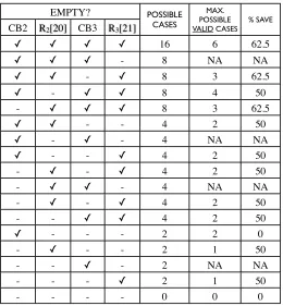
EMPTY? POSSIBLE
CASES
MAX. POSSIBLE VALID CASES
% SAVE
CB2 R2[20] CB3 R3[21]
✓ ✓ ✓ ✓ 16 6 62.5
✓ ✓ ✓ - 8 NA NA
✓ ✓ - ✓ 8 3 62.5
✓ - ✓ ✓ 8 4 50
- ✓ ✓ ✓ 8 3 62.5
✓ ✓ - - 4 2 50
✓ - ✓ - 4 NA NA
✓ - - ✓ 4 2 50
- ✓ - ✓ 4 2 50
- ✓ ✓ - 4 NA NA
- ✓ - ✓ 4 2 50
- - ✓ ✓ 4 2 50
✓ - - - 2 2 0
- ✓ - - 2 1 50
- - ✓ - 2 NA NA
- - - ✓ 2 1 50
- - - - 0 0 0
Fig. 4.All possibilities during Processing-Phase2
Whenever the CB of registerR3is vacant, the bitR3[21] has to be vacant too. Hence there are some cases in the following table which arenot applicable(NA). The last column depicts the percentage of the total possible cases that are discarded due to the attack algorithms.
In the determination phase, a total of 7 bits (i.e.,R2[21],R2[20],R2[10], R3[22],R3[21],
R3[10] andR3[7]) have to be determined. These 7 bits would have 27 = 128 possible com-binations. But our algorithms give only 24 valid possible comcom-binations. Thus saving 104 combinations i.e., a saving of 81.25%.
IfR3[7] is not considered, the first round of implementation will always generate 12 state candidates. On an average, the second round generates 60 state candidates and the third round generates 300 state candidates. The number of state candidates (till round 10) can be approximated by the formula 12∗5n−1, wherendenotes thenthround,n∈
6
Discussion
We discuss in detail a probabilistic approach to determine the time complexity, the storage requirement and success probability of our new attack. The results of this probabilistic approach are also corroborated by experimental data. According to these results, the average number of rounds necessary to get the key is 15.5 and the average number of complete state candidates obtained after 15.5 rounds is 248.5.
We conclude this section with a comparison of our attack implementation results with the guess-and-determine attacks already known.
6.1 Time complexity
Now we understand the exact time-complexity of our attack algorithm. According to the algorithm, work done is during:
– Checking to see if a cell in a register is vacant or full
– Replication of state candidates
– Filling up vacant bits
It is reasonable to assume that the checking and filling of bits take negligible amount of time. Hence, we can safely assume that the unit of our time complexity measurement should be the number of replications needed, where one unit of time is one replication. The algorithm starts with registersR2andR3vacant and registerR1filled (guessed). At the end, it creates about 248.5 complete state candidates, i.e., 248.5replications.
The number of bits between the clocking bit (CB) and the most significant bit (MSB) for registerR2is 10 and for registerR3is 11. Hence, the number of times the registersR2andR3 have to be clocked to determine all the bits of that register is at least 10 and 11 respectively. The minimum number of KS bits required to obtain a set of complete state candidates (with no vacant bits) is 11. This will occur when both registers R2 and R3 are clocked together for 10 consecutive clocking cycles and register R3 is clocked again in the following round. With every clocking round, the number of complete state candidates increases. Hence, the probability of finding the key increases with every additional round of clocking, after 11 rounds.
According to themajority function of theclocking rule for theA5/1, a register will get clocked 3 out of 4 times. At every clocking cycle, at least two registers will get clocked. Let n1 be the event that registers R2 and R3 are clocked together, and n2 be the event that register R1 is clocked either with register R2 or with register R3. The probabilities that eventsn1andn2occur are given byP(n1) andP(n2) respectively. Letn02be the event that only registers R1 and R2 are clocked. Let n002 be the event that only registers R1 and R3 are clocked. The probabilities that events n02 and n002 occur are given by P(n02) and P(n002) respectively. Hence, one concludes thatP(n1) =P(n2) = 12. Thus:
P(n1) +P(n2) = 1 and P(n2) =P(n02) +P(n002) = 1 4 +
1
4. (2)
i.e.,
P(n1) +P(n02) +P(n
00
Registers R2 andR3 have to be clocked at least 10 and 11 times respectively to determine all bits of that register, i.e., to obtain a set of complete state candidates. We assume that they were clocked n1or n2respectively for the attack to stop.
LetX be the random variable denoting the number of clocking cycles needed to obtain complete state candidate. Letx1 be the number of clocking cycles needed for event n1,x2 for n02 and x3 for n200. Here, x1 = 10, x2 = 10 andx3 = 11. Then the expectation for this variableX is defined as
E[X] = x1∗P(n1) +x2∗P(n 0
2) +x3∗P(n002)
P(n1) +P(n02) +P(n002)
= 10∗ 1
2+ 2∗(10∗ 1 4+ 11∗
1 4) 1
2+ 1 4+
1 4
= 15.5
An Experiment We implement normal encryption of A5/1 using random inputs for all three registers. The aim of this experiment is to determine the average number of clocking rounds needed for register R2 and R3 to be clocked at least 10 and 11 times respectively. We performed this experiment thrice, each time with 250 inputs. The average number of clocking rounds needed turned out to be 15.51 with a standard deviation of 1.785. Hence, the experimental results corroborate with the theoretical proof.
So we conclude, that the minimum number of clocking cycles necessary to obtain a set of complete state candidates is 11, and after 15.5 rounds there is a very high probability that the set of complete state candidates contain the key. Experimental results show us that after 11 rounds we get about 240complete state candidates.
6.2 Storage Requirement and Success Probability
As discussed in Section 4.1, the minimum number of KS bits required to generate a set of complete state candidates (all bits filled) is 11. With every additional clocking round, the number of complete state candidates increase. We can start the post-processing-phase of the attack after round 11 simultaneously with the determination phase of the attack. Hence, the probability of finding the key also increases with every round. But we require at least 64 KS bits for the post-processing-phase of the attack to check for the key.
In Table 2, we describe the data obtained from our humble experiments with this at-tack. The four columns of the table are: number of clocking rounds; total number of state candidates obtained after that round; total number of complete state candidates obtained; and the percentage of complete state candidates over the total number of state candidates for that particular round. All values of the experimental data in the table are approximated to one decimal place.
Remark: In each round, the number of possible choices reduce to at least half of the number for an exhaustive search (refer Figure 4). Hence, a minimum saving of 50% takes place in every round over exhaustive search (all possible choices). As stated in Section 6.1, the average number of rounds to get the key is around 15.5. In each round, we save at least half the possible cases. Hence for 15.5 rounds we save (12)15.5cases. Thus, the average number of complete state candidates obtained after 15.5 rounds will be (264)(1
2)
Table 2.Storage Requirement and Success Probability
No. of Rounds Total State Candidates Complete State Candidates CompleteT otal ×100
11 245.2 239.2 1.6%
12 246.0 242.5 9.0%
13 246.7 244.5 22%
14 246.9 245.3 30%
15 247.1 246.1 50%
would be among the set of complete state candidates obtained after the 15th round, with a probability higher than 50%.
Storage For each guess of 19 bits of registerR1, we require storage of 100MB to determine registersR2andR3and the known keystream KS. If we do not find the key for this choice of 19 bits for registerR1, then we discard this guess and make a new guess for register R1. In the worst case scenario, we would check all 219 possible choices for registerR1. The attack has a 100% success probability and requires about 5.65GB storage.
Comparison of the known guess-and-determine attacks on the A5/1 We conclude this section with a comparison of our attack with other guess-and-determine attacks already known. The following table (Table 3) lists the necessary amount of known keystream bits (KS), the time complexity and the success probability for each attack.
Table 3.Comparison of the known guess-and-determine attacks on the A5/1
Attack KS bits Time Success Notes
complexity probability Storage
Anderson’s Attack[1] 64 252 100%
-Golic’s Attack[11] 64 240.16 100% Additionally solve 64x64 Linear System of Equations Biham-Dunkelman’s Attack[4] 220.8 247 63%
-Keller-Seitz’s Attack[13] 64 251.24 18%
-GNR’s Attack[10] 64 254.02 100%
-BSW’s Attack[5] 64 248 60%
-Our Attack 64 248.5 100% 5.65GB
7
Conclusion
Our attack is based on the guess-and-determine approach proposed by Anderson [1], but with several modifications. In this attack, all bits of the first register R1 are assumed to be known and all bits of registers R2 and R3 are determined with 64 bits of the known
This attack has an average time complexity of 248.5, which is much smaller than an exhaustive search. The average number of rounds necessary to obtain the correct key from the set of complete state candidates is 15.5. With every round of clocking after 11 rounds, the number of complete state candidates increases. Thus, the probability of finding the key increases with every clocking round. One can do the post-processing phase for a round simultaneously with the determination phase for the next round, and thus save time. The attack is successful with 100% probability and requires about 5.65GB storage. With this we conclude that our attack is better than all known guess-and-determine attacks on theA5/1 stream cipher.
References
1. Anderson, R.,A5 (was: Hacking digital phones), http://yarchive.net/phone/gsmcipher.html, Newsgroup Communication, 1994.
2. Babbage, S.,A Space/Time Tradeoff in Exhaustive Search Attacks on Stream Ciphers, Euro-pean Convention on Security and Detection, 1995.
3. Barkan, E., Biham, E., and Keller, N.,Instant Ciphertext-only Cryptanalysis of GSM Encrypted Communication, Technical Report CS-2006-07, Technion, 2006.
4. Biham, E. and Dunkelman, O., Cryptanalysis of the A5/1 GSM Stream Cipher, In Proc. of Indocrypt’00, vol 1977 of LNCS. Springer-Verlag, 2000.
5. Biryukov, A., Shamir, A. and Wagner, D.,Real Time Cryptanalysis of A5/1 on a PC, In Proc. of FSE’00, vol 1978 of LNCS, pp 1-18. Springer-Verlag, 2001.
6. Briceno, M., Goldberg, I., and Wagner, D.,A Pedagogical Implementation of the GSM A5/1 and A5/2 “voice privacy” Encryption Algorithms, http://cryptome.org/gsm-a512.html, 1999. 7. Donald, E.,Introduction to Combinatorial Algorithms and Boolean functions. The Art of
Com-puter Programming. 4.0, Upper Saddle River, NJ: Addison-Wesley. pp 64-74, 2008.
8. Ekdahl, P. and Johansson, T.,Another Attack on A5/1, IEEE Transactions on Information Theory, 49(1), pp 284-289, 2003.
9. Gendrullis, T., Hardware-Based Cryptanalysis of the GSM A5/1 Encryption Algorithm, Diploma thesis, Ruhr-University Bochum 2008.
10. Gendrullis, T., Novotny, M., and Rupp, A.,A Real-World Attack Breaking A5/1 within Hours, Proc. of CHES’08, vol 5154 of LNCS, pp 266-282. Springer-Verlag, 2008.
11. Golic, J.,Cryptanalysis of Alleged A5 Stream Cipher, In Proc. of Eurocrypt’97, vol 1233 of LNCS, pp 239-255. Springer-Verlag, 1997.
12. Hillebrand, Friedhelm,GSM and UMTS: The creation of Global Mobile Communication, Wiley 2002.
13. Keller, J., and Seitz, B., A Hardware-Based Attack on the A5/1 Stream Cipher, http://pv.fernuni-hagen.de/docs/apc2001-final.pdf, 2001.
14. Kostopoulos, G., Sklavos, N., Galanis, M., and Koufopavlou, O., VLSI Implementation of GSM Security: A5/1 and W7 Ciphers, In Proc. of IEEE Workshop on Wireless Circuits and Systems (IEEE WoWCAS’04), Canada, 2004.
15. Maximov, A., Johnasson, T. and Babbage, S.,An Improved Correlation Attack on A5/1, In Proc. of SAC’04, vol 3357 of LNCS, pp 239-255. Springer-Verlag, 2005.
16. Menezes, A., van Oorschot, P., and Vanstone, S., Handbook of Applied Cryptography, CRC Press, 1997.