INSTALLATION GUIDE
NEC America, Inc.
NEC America reserves the right to change the specifications, functions, or features in this document at any time without notice. NEC America has prepared this document for use by its employees and customers. The information contained herein is the property of NEC America and shall not be reproduced without prior written approval from NEC America.
Copyright 1996
TABLE OF CONTENTS
Page
Chapter 1 - Introduction . . . 7
General Description of UCD-XL . . . 7
Installation Overview. . . 8
Components. . . 8
Installation Steps . . . 8
Additional Documentation . . . 9
Manual Organization. . . 9
Chapter 2 - Installation . . . 11
Installing UCD-XL . . . 11
UCD-XL Monitor. . . 12
UCD-XL Mediator. . . 18
UCD-XL Messenger . . . 23
UCD-XL Administrator . . . 26
Miscellaneous Set Up . . . 29
Chapter 3 - Configuring UCD-XL . . . 31
Application Characteristics . . . 31
Primary Configuration Parameters . . . 32
Facilities . . . 33
OAI Configuration . . . 33
User-Defined Parameters . . . 35
Monitor User-defined Parameters . . . 36
Messenger User-defined Parameters . . . 37
Mediator User-defined Parameters . . . 38
Administrator User-defined Parameters. . . 40
Chapter 4 - Database Requirements . . . 41
Instructions . . . 41
Group Identification Database . . . 42
Port Assignment Database . . . 44
ANI Pattern Database . . . 44
Chapter 5 - MAT Assignments . . . 47
Chapter 6 - Initialization and Termination . . . 49
Initialization . . . 49
Termination . . . 49
Appendix A - Error Messages. . . 51
Error Messages from UCD-XL Monitor . . . 51
Error Messages from UCD-XL Messenger . . . 58
Error Messages from UCD-XL Mediator . . . 60
Error Messages from UCD-XL Administrator . . . 62
Page
Appendix B - UCD-XL Utilities . . . 69
LIST OF FIGURES
Figure Title Page
LIST OF TABLES
Table Title Page
3-1 UCD-XL Component Characteristics. . . 31
3-2 Primary Configuration Parameters . . . 32
3-3 Facilities . . . 33
3-4 Monitor Parameters. . . 34
3-5 Messenger Parameters . . . 35
3-6 Monitor User-defined Parameters . . . 36
3-7 Messenger User-defined Parameters . . . 37
3-8 Mediator User-defined Parameters . . . 38
3-9 Administrator User-defined Parameters . . . 40
4-1 Group Identification Database . . . 42
4-2 Port Assignment Database . . . 44
4-3 ANI Pattern Database . . . 45
C-1 RJ-45 Pin Assignments for NEC Multi-8/16 Board . . . 72
C-2 Adapter for Multi-8/16 to PBX . . . 72
C-3 Adapter for Multi-8/16 to VMS . . . 73
C-4 RJ-45 and DB-25 Pin Assignments for DigiCHANNEL . . . 74
Chapter 1
Introduction
General Description of UCD-XL
UCD-XL is an Open Applications Interface (OAI) application that expands the capabilities of Uniform Call Distribution (UCD) in the NEAX2400 PBX. Although the PBX is limited to 60 extensions in a UCD group, this application can route a call to any extension in a group of any size (subject to a practical limit of 150 voice mail ports). Multiple UCD groups are supported. The application also monitors the calls and maintains cumulative statistics which can be reported.
UCD-XL has the ability to distribute calls to groups based upon the automatic number identification (ANI) of the call. Separate statistics are maintained for ANI patterns.
UCD-XL, which resides on the User Application Processor (UAP), may communicate with a voice mail system (VMS) via the standard Message Center Interface (MCI) link, as shown in Figure 1-1. When an incoming call is connected to a voice port, a message is sent to the VMS, identifying the originator and the port. The VMS, in turn, sends a message to the UAP controlling a message waiting lamp (MWL). UCD-XL passes this MCI message unaltered to the PBX.
Figure 1-1 UCD-XL Environment with a VMS
UCD-XL is able to receive calls across a CCIS network of PBXs. However, all extensions comprising the managed groups must reside on the PBX connected to the User Application Processor. Office codes are supported, and may be omitted or truncated in MCI messages.
If UCD-XL detects a failure of the OAI link with the PBX, the application will switch to passive mode. In this passive mode, UCD-XL passes MCI messages between the PBX and the VMS. Once the OAI link is reestablished, UCD-XL will restore full functionality.
VMS
MCI
UAP (UCD-XL) NEAX2400
OAI voice ports
Installation Overview
This guide describes the procedures to follow and specific information to use during the installation and configuration of UCD-XL.
Components
There are a minimum of four component applications to UCD-XL.• Monitor Provides call processing functions; specifically, Monitor intercepts calls and routes them to a port of an appropriate UCD group.
• Mediator Receives and transmits MCI messages between the PBX and the VMS.
• Messenger Connects calls to ports, and checks port status. UCD-XL may have more than one Messenger.
• Administrator Generates statistics of UCD call activity, and provides the capability to dynamically trace UCD call activity.
During installation, components are configured sequentially. The Mediator component is required only if a Voice Mail System will be used for one of the UCD groups. After installation, each can be configured separately using the APM, as described on page 31.
Installation Steps
Briefly, the installation and set up of UCD-XL involves the following sequence of steps. These steps are described in detail in the chapters of this guide.• Software Installation - First load the UCD-XL software from the release
media. Log in to the APM Platform Management Menu, select the Installation of Applications/Packages option, and follow the instructions provided in the APM Installation Manual to complete this part of the installation. Refer to page 11 for more information.
• Application Configuration - UCD-XL is internally supported by the APM,
and must be configured in the APM environment. UCD-XL is comprised of (at least) four internal components, of which three must be configured. Either respond to the prompts during installation, or use the instructions provided in the APM Operations Manual to make the entries contained in this section. Refer to page 31 for more information.
• Database Requirements - UCD-XL requires two databases which are
• Initialization/Termination - All UCD-XL components must be initialized and
terminated through the APM Operations Menu. These actions and their sequencing among the components are discussed on page 49. Use the
instructions provided in the APM Operations Manual. Refer to page 49 for more information.
• Backups - It is recommended that a backup of the “oai” filesystem be made on
diskettes (device name “/dev/rfd0”) or cartridge tape (“/dev/rct0”) immediately after completing the installation and configuration of UCD-XL and its
databases. Refer to the SCO UNIX System Administrators Guide for instructions.
Additional
Documentation
In addition to this guide, use instructions in the following manuals to aid with this installation:
• Applications Manager (APM) Installation Manual - Contains step-by-step
instructions for installing the software from the release media.
• NEAX2400 System Manuals - Give very detailed explanations about the
assignments that need to be made through the Maintenance Administration Terminal (MAT) commands on the NEAX2400.
• Applications Manager (APM) Operations Manual - Explains how
applications like UCD-XL are configured in the APM environment, and how its databases are created, using the entries and values provided in this chapter.
Manual Organization
This guide contains the following chapters:
Chapter 1: Introduction A brief explanation of UCD-XL.
Chapter 2: Installation How to install UCD-XL. Chapter 3: Configuration How to configure UCD-XL. Chapter 4: Database Requirements A description of database
re-quirements.
Chapter 5: MAT Assignments How to make data settings for the MAT.
Chapter 6: Initialization/Termination How to initialize and terminate UCD-XL.
Appendix A: Error Messages UCD-XL error messages. Appendix B: Utilities UCD-XL Utilities.
Chapter 2
Installation
This chapter provides instructions for installing the UCD-XL software. In addition to the information in this chapter, you can refer to the Applications Manager
(APM) Installation Manual for more information on installing software from
release media.
Installing UCD-XL
Begin the installation of UCD-XL by loading the UCD-XL software from the release media. Log in to the APM Platform Management Menu, select the Installation of Applications/Packages option, and follow the instructions provided in the APM Installation Manual to complete this part of the installation.
When the software has been loaded, the installation software displays the message
E34H< 9^cdQ\\QdY_^ @b_SUTebU V_b C3? E>9H
The installation software issues the following prompts, one at a time.1
4_ i_e gQ^d d_ S_^VYWebU E34H< =_^Yd_b Qd dXYc dY]U i _b ^/ 4_ i_e gQ^d d_ S_^VYWebU E34H< =UTYQd_b Qd dXYc dY]U i _b ^/
4_ i_e gQ^d d_ S_^VYWebU _^U _b ]_bU =UccU^WUbc Qd dXYc dY]U i _b ^/ 4_ i_e gQ^d d_ S_^VYWebU E34H< 1T]Y^YcdbQd_b Qd dXYc dY]U i _b ^/
If you type n and press Enter after any of the above prompts, the installation software issues the next prompt in the sequence.
If you type y and press Enter after any of the above prompts, the installation software immediately begins the configuration of that component, before issuing the next prompt in the above sequence. Once the configuration of a component begins, see the appropriate section:
• UCD-XL Monitor on page 12. • UCD-XL Mediator on page 18. • UCD-XL Messenger on page 23. • UCD-XL Administrator on page 26.
After one or more components have been successfully configured, the installation software performs some set-up tasks that require you to enter the root password. That procedure is described in Miscellaneous Set Up on page 29.
If, at any time, you quit the installation of UCD-XL, the installation software displays the following message and prompt:
9^cdQ\\QdY_^ QR_bdUT
@bUcc 5^dUb [Ui d_ bUdeb^ d_ dXU 1@= @\QdV_b] ]U^e
This usually means that the configuration data for the current component has been lost. After pressing the Enter key, you may repeat the installation procedure from the beginning (re-loading the UCD-XL software), or you may manually configure the components as described on page 31.
UCD-XL Monitor
The primary function of the UCD-XL Monitor is to intercept calls and route them to an available port of an appropriate UCD group. The Monitor is a required component of UCD-XL.To configure the UCD-XL Monitor, perform the following steps. 1. The installation software displays the message
DXU bUS_]]U^TUT ^Q]U V_b dXU S_]`_^U^d Yc E34H<O=_^Yd_b
The installation software issues the prompt
9c dXYc QSSU`dQR\U/ i _b ^
2. If you want UCD-XL_Monitor to be the name of the Monitor component, type
y and press Enter. Go to step 4.
If you want to assign a different name, type n and press Enter. The installation software issues the prompt
5^dUb dXU TUcYbUT ^Q]U V_b dXU =_^Yd_b .
3. Type the new name for the UCD-XL Monitor and press Enter. Any embedded blanks in the name will be converted to underscores. The installation software displays the message
DXU =_^Yd_b S_]`_^U^d cXQ\\ RU ^Q]UT ,=_^Yd_b ^Q]U.
where <Monitor name> is the name assigned to the UCD-XL Monitor. 4. The installation software issues the command
CU\USd dXU c_ebSU Q^T TUcdY^QdY_^ \Y^[c Vb_] dXU V_\\_gY^W \Ycd*
K!M c_ebSU* ?19!D3@ TUcd* @2H!D3@ D3@9@ `b_d_S_\
K"M c_ebSU* ?19!H"% TUcd* @2H!H"% H"% `b_d_S_\
K)M _dXUb c`USYVi
KaM aeYd Y^cdQ\\QdY_^
The installation software issues the prompt
7. Type in the destination link and press Enter.
The source and destination links are names that identify sets of OAI communication characteristics between the UAP (source) and the PBX (destination). These names are defined under the System Configuration Menu of APM System Administration. Refer to the APM Operations Manual for further information.
8. After entering the selection (or entering the names of the source and destination links), the installation software displays the following message:
C_ebSU gY\\ RU ,c_ebSU \Y^[ ^Q]U. 4UcdY^QdY_^ gY\\ RU ,TUcdY^QdY_^ \Y^[ ^Q]U.
where <source link name> and <destination link name> are the names of the source and destination links, respectively. (The names are automatically converted to uppercase.)
9. The installation software issues the prompt
GY\\ i_e TYcdbYRedU SQ\\c RQcUT e`_^ 1>9 TQdQ bUaeYbY^W ecU _V dXU 1>9 @QddUb^ 4QdQRQcU/ i _b ^
Type y for yes or n for no, and press Enter.
If you answer yes, you must provide records for the ANI Pattern Database after the installation is complete. (See page 44.) The following message displays:
DXU 1>9 @QddUb^ 4QdQRQcU gY\\ RU ecUT
If you answer no, the following message displays:
1>9RQcUT TYcdbYRedY_^ gY\\ ^_d _SSeb
10.The installation software issues the prompt
C`USYVi dXU TUVQe\d VbUaeU^Si _V `_bd Y^c`USdY_^c Y^ ]Y^edUc TUVQe\d Yc # >?D5* DXYc fQ\eU ]Qi RU _fUbbYTTU^ V_b Y^TYfYTeQ\ Wb_e`c Y^ dXU 7b_e` 4QdQRQcU
11.Type the frequency of port inspections, and press Enter. If you do not want the Monitor to verify the statuses of the ports of a group, specify 0 here and in the appropriate record of the Group Identification Database.
Note: Keep in mind that if the Monitor mistakenly thinks a port is busy, it will not con-nect any calls to that port, even though the port is really free. An inspection will rectify such errors.
The installation software displays the message
9^c`USdY_^c gY\\ _SSeb UfUbi ,Y^c`USdY_^ VbUaeU^Si. ]Y^edUc
12.The installation software issues the command
CU\USd dXU di`U _V cdQdYcdYSc Vb_] dXU V_\\_gY^W \Ycd*
K!M Q\\ cdQdYcdYSc ]QZ_b Q^T ]Y^_b
K"M ]QZ_b cdQdYcdYSc _^\i
K#M ^_^U
KaM aeYd Y^cdQ\\QdY_^
The installation software issues the prompt
5^dUb RbQS[UdUT fQ\eU .
13.Type the number corresponding to the statistics you want, and press Enter. Major statistics cover call activity per group, and include incoming call count, abandoned call count, queued call count, and average and maximum durations of queued calls. Minor statistics apply to each port within a group, and include connected call count and average and maximum durations of connected calls. The installation software displays the following message:
,cdQdYcdYSc di`U. gY\\ RU `b_fYTUT
where <statistics type> is the statistics type you selected.
14.If you selected option [3] above, the installation continues with step 16. Other-wise, the installation software displays the following prompt:
CU\USd dXU cdQdYcdYSc S_\\USdY_^ `UbY_T Vb_] dXU V_\\_gY^W \Ycd*
K!M X_eb\i
K"M TQY\i
KaM aeYd Y^cdQ\\QdY_^
5^dUb RbQS[UdUT fQ\eU .
15.Type the number corresponding to the statistics collection period you want, and press Enter.
The first option, “hourly”, means that statistics are computed and recorded at the top of every hour. The second option, “daily”, means statistics are computed and recorded at midnight of every day. The installation software displays the
following message:
CdQdYcdYSc gY\\ RU S_\\USdUT ,cdQdYcdYSc S_\\USdY_^ `UbY_T.
where <statistics collection period> is the statistics collection period
16.The installation software issues the following message and prompt:
DXU =_^Yd_b S_]]e^YSQdUc gYdX _^U _V ]_bU =UccU^WUbc Ri ]UQ^c _V
´bUaeUcd RY^cµ Y^ cXQbUT ]U]_bi DXU aeQ^dYdi _V bUaeUcd RY^c ^UUTUT
Yc RQcUT e`_^ SQ\\ dbQVVYS f_\e]Uc CU\USd Vb_] dXU V_\\_gY^W \Ycd*
K!M c`USYVi aeQ^dYdi
K"M " RY^c !"))) SQ\\cX_eb
K#M # RY^c # $))) SQ\\cX_eb
K$M $ RY^c % SQ\\cX_eb
KaM aeYd Y^cdQ\\QdY_^
5^dUb RbQS[UdUT fQ\eU .
17.Type the number corresponding to the number of request bins you want, and press Enter. If you choose option [2], [3], or [4], go to step 19. If you choose [1], the installation software issues the prompt
9^fQ\YT _`dY_^ 8_g ]Q^i bUaeUcd RY^c/ .
18.Type in the number of request bins you want and press Enter. 19.The installation software displays the following message:
,bUaeUcd RY^c. bUaeUcd RY^c gY\\ RU Q\\_SQdUT
where <request bins> is the number of request bins you selected.
20.The installation software issues the prompt:
21.Type y or n to indicate whether or not you will use UCD-XL for voice mail ac-cess, and press Enter.
If you respond with an n, the installation software displays the following message:
DXU =UTYQd_b S_]`_^U^d gY\\ ^_d RU S_^VYWebUT
and installation of the UCD-XL Monitor continues with step 25.
If you respond with a y, the installation software displays the following message:
E34H< =UTYQd_b Yc ^USUccQbi d_ ]Q^QWU dXU =39 \Y^[ DXU bUS_]]U^TUT ^Q]U V_b dXU S_]`_^U^d Yc E34H<O=UTYQd_b
The installation software issues the prompt
9c dXYc QSSU`dQR\U/ i _b ^
22.If you want UCD-XL Mediator to be the name for the Mediator component, type y and press Enter. The installation continues with the message displayed in step 23. If you want to assign a different name, type n and press Enter. The installation software displays the following message:
5^dUb dXU TUcYbUT ^Q]U V_b dXU =UTYQd_b
23.Type in the new name for the Mediator and press Enter. The installation software displays the following message:
DXU =UTYQd_b S_]`_^U^d cXQ\\ RU ^Q]UT ,=UTYQd_b ^Q]U.
where <Mediator name> is the name assigned to the UCD-XL Mediator.
Note: After the Monitor has been configured, the configuration of the Mediator begins immediately with step 3 on page 18.
24.The installation software issues the prompt
GXQd Yc dXU c_ebSU _V dXU ]QY\R_h ^e]RUb dXQd gY\\ RU `\QSUT Y^ dXU =39 ]UccQWU V_b Q TYbUSd SQ\\ d_ dXU F=C/
K!M QSdeQ\ \Y^U _V dXU SQ\\ K"M ]i \Y^U `XicYSQ\ UhdU^cY_^ KaM aeYd Y^cdQ\\QdY_^
5^dUb RbQS[UdUT fQ\eU .
25.The installation software issues the prompt
9c dXYc S_^VYWebQdY_^ _V dXU =_^Yd_b QSSU`dQR\U/ i _b ^
If you are satisfied with this configuration, type y and press Enter. This ends the installation of UCD-XL Monitor.
If you made a mistake during this configuration, type n and press Enter; installation of the UCD-XL Monitor starts over at step 1 on page 12.
26.The installation software displays the following messages (if installing for the first time):
_QYedY\cQed_SVW be^^Y^W
_QYedY\cQed_SVW* ,=_^Yd_b ^Q]U. Q``\YSQdY_^ S_^VYWebUT
_QYedY\cQed_SVW dUb]Y^QdUT ^_b]Q\\i
E34H< =_^Yd_b S_^VYWebQdY_^ S_]`\UdUT
If you are upgrading UCD-XL, you will see the following messages:
_QYedY\cQed_SVW be^^Y^W
_QYedY\cQed_SVW* ,=_^Yd_b ^Q]U. Yc Q\bUQTi S_^VYWebUT
_QYedY\cQed_SVW* BUS_^VYWebU i^/
Answer y to change the configuration, and n to keep the original setting.
UCD-XL Mediator
The UCD-XL Mediator receives and transmits MCI messages between the PBX and the VMS. If you are not using a Voice Mail System, you do not need to configure the UCD-XL Mediator.If you have just finished configuring the UCD-XL Monitor, go to step 3 below to configure the UCD-XL Mediator; otherwise, begin configuration of the UCD-XL Mediator with step 1.
1. The installation software displays the following message
DXU bUS_]]U^TUT ^Q]U V_b dXU Q``\YSQdY_^ Yc E34H<O=UTYQd_b
The installation software issues the prompt
9c dXYc QSSU`dQR\U/ i _b ^
If UCDXL_Mediator is the name you want to use for the Mediator component, type y and press Enter. Mediator installation continues with step 3.
If you want to assign a different name, type n and press Enter. The installation software issues the prompt
5^dUb dXU TUcYbUT ^Q]U V_b dXU =UTYQd_b .
2. Type the desired name for the Mediator and press Enter. Any embedded blanks in the name will be converted to underscores. The following message displays:
DXU =UTYQd_b S_]`_^U^d cXQ\\ RU ^Q]UT ,=UTYQd_b ^Q]U.
where <Mediator name> is the name assigned to the UCD-XL Mediator. 3. The installation software issues the command
CU\USd dXU =39 ]UccQWU cUd d_ ecU Vb_] dXU V_\\_gY^W \Ycd*
K!M cdQ^TQbT =39 TUcSbYRUT Y^ 5D9!"! c`USYVYSQdY_^ K"M Uh`Q^TUT =39 ]ecd cUd 1CI4* cic ! Y^TUh "$& RYd # KaM aeYd Y^cdQ\\QdY_^
>_dU* I_eb F=C ]ecd ce``_bd dXU TUcYbUT ]UccQWU cUd
The installation software issues the prompt
4. Type the number corresponding to the MCI message set you want, and press
Enter.
For either MCI option, you must also configure the PBX to enable the MCI. See MAT Assignments, on page 47.
The installation software displays the following message:
=39 ]UccQWU cUd gY\\ RU ,=39 ]UccQWU cUd.
where <MCI message set> is the MCI message set you selected.
5. The installation software issues the prompt
C`USYVi TUfYSU ^Q]U _V dXU =39 `_bd d_ dXU @2H ´aµ d_ aeYd .
To quit the installation, type q and press Enter.
6. Type the UNIX device name of the MCI port to the PBX, and press Enter. If you have installed a Digiboard for serial communications, the device names range from “ttyi1a” to “ttyi1p”.1
If the specified device does not exist or corresponds to the virtual terminal you are using, the installation software displays an appropriate message and prompts you for the device name again. Type another UNIX device name of the MCI port to the PBX, and press Enter.
7. The installation software issues the command
CU\USd dXU RQeT bQdU V_b dXU @2Hµc =39 `_bd Vb_] dXU V_\\_gY^W \Ycd*
K!M !" K"M "$
K#M $(
K$M )& K%M !)"
KaM aeYd Y^cdQ\\QdY_^
The installation software issues the prompt
5^dUb RbQS[UdUT fQ\eU .
8. Type the number corresponding to the baud rate you want, and press Enter. The baud rate must match the configuration on the PBX side. See MAT Assignments, on page 47.
9. The installation software issues the command
CU\USd dXU `QbYdi _V dXU @2Hµc =39 `_bd Vb_] V_\\_gY^W \Ycd*
K M ^_^U
K!M _TT
K"M UfU^
KaM aeYd Y^cdQ\\QdY_^
The installation software issues the prompt
5^dUb RbQS[UdUT fQ\eU .
10.Type the number corresponding to the parity you want, and press Enter. The parity must match the configuration on the PBX side. See MAT Assignments, on page 47.
11.The installation software issues the command
CU\USd dXU aeQ^dYdYUc _V TQdQ Q^T cd_` RYdc Vb_] V_\\_gY^W \Ycd*
K!M ' TQdQ ! cd_`
K"M ' TQdQ " cd_`
K#M ( TQdQ ! cd_`
K$M ( TQdQ " cd_` KaM aeYd Y^cdQ\\QdY_^
The installation software issues the prompt
5^dUb RbQS[UdUT fQ\eU .
12.Type the number corresponding to the data and stop bits you want, and press
Enter.
The quantities must match the configuration on the PBX side. See MAT Assignments, on page 47.
The installation software displays the following message
@2Hµc =39 `_bd Yc TUf,=39 @2H `_bd TUfYSU ^Q]U.* ,RQeT bQdU. RQeT ,`Qb Ydi. `QbYdi ,TQdQ RYdc. RYdc ,cd_` RYdc. cd_`
where:
<MCI PBX port device name> is the device name you entered for the MCI port to the PBX;
<baud rate> is the baud rate you selected for the port; <parity> is the parity you selected for the port;
13.The installation software issues the prompt
C`USYVi TUfYSU ^Q]U _V dXU =39 `_bd d_ dXU F=C ´aµ d_ aeYd .
To quit the installation, type q and press Enter.
14.Type the UNIX device name (must be different from the device name for the port to the PBX) of the MCI port to the VMS, and press Enter.
If the specified device does not exist, is the same as the device name for the PBX port, or corresponds to the virtual terminal you are using, the installation software displays an appropriate message and prompts you for the device name. Type another UNIX device name for the MCI port to the VMS, and press Enter. 15.The installation software displays the following message
F=Cµc =39 `_bd Yc TUf,=39 F=C `_bd TUfYSU ^Q]U.* ,RQeT bQdU. RQeT ,`Qb Ydi. `QbYdi ,TQdQ RYdc. RYdc ,cd_` RYdc. cd_`
where:
<MCI VMS port device name> is the device name you entered for the MCI port to the VMS;
<baud rate> is the baud rate you selected for the PBX port; <parity> is the parity you selected for the PBX port;
<data bits> and <stop bits> are the number of data bits and stop bits you se-lected for the PBX port.
Note: It is assumed that the communication characteristics for the VMS are the same as for the PBX. If this is not the case, you may modify Mediator’s configuration through the APM. See page 38.
16.If you have not configured the Monitor during this session, the installation soft-ware issues the following prompt
5^dUb dXU Q``\YSQdY_^ ^Q]U _V dXU =_^Yd_b Qc [^_g^ d_ dXU 1@= TUVQe\d Yc E34H<O=_^Yd_b .
17.Type the name which was assigned to the Monitor and press Enter, or press
En-ter to accept the default of UCDXL_Monitor. The installation software issues
the message
=_^Yd_bµc ^Q]U Yc ,=_^Yd_b ^Q]U.
18.The installation software issues the prompt:
4_ i_e gQ^d E34H< d_ _]Yd _VVYSU S_TUc Vb_] =39 ]UccQWUc/ i _b ^
19.If your PBX network uses office codes but you do not want them conveyed to the VMS, type y and press Enter. The installation of Mediator continues with step 20. If you do not use office codes or you want them included in MCI mes-sages, type n and press Enter. The installation continues with step 22.
20.If you responded with y, the installation software issues the prompt:
21.Enter the number of digits (from 1 to 4) comprising an office code. UCD-XL will use this value to truncate or erase any office code that precedes an extension number identifying a calling, called, or intermediate party. If you specify 0 (the default), office codes will be included in MCI messages to the VMS.
22.The installation software displays one of the following messages, depending upon your responses:
?VVYSU S_TUc _V ,_VVS_TU \U^WdX. TYWYdc gY\\ RU _]YddUT
or:
?VVYSU S_TUc YV WYfU^ gY\\ RU `ed Y^ =39 ]UccQWUc
23.The installation software issues the prompt
9c dXYc S_^VYWebQdY_^ _V dXU =UTYQd_b QSSU`dQR\U/ i _b ^
If you made a mistake during this configuration, type n and press Enter; installation of the UCD-XL Mediator starts over at step 1 or step 3, as appropriate.
If you are satisfied with this configuration, type y and press Enter. 24.The installation software displays the following messages:
_QYedY\cQed_SVW be^^Y^W
_QYedY\cQed_SVW* ,=UTYQd_b ^Q]U. Q``\YSQdY_^ S_^VYWebUT
_QYedY\cQed_SVW dUb]Y^QdUT ^_b]Q\\i
E34H< =UTYQd_b S_^VYWebQdY_^ S_]`\UdUT
UCD-XL
Messenger
UCD-XL uses Messengers to check the statuses of the ports of its UCD groups, and to connect calls to the ports. At least one Messenger is required; a total of three Messengers may be needed as call traffic increases.
To configure the UCD-XL Messenger(s), perform the following steps. 1. The installation software issues the command
DXU aeQ^dYdi _V =UccU^WUbc Yc b_eWX\i RQcUT e`_^ SQ\\ dbQVVYS f_\e]Uc CU\USd Vb_] V_\\_gY^W \Ycd*
K!M ! =UccU^WUb !#$)) SQ\\cX_eb
K"M " =UccU^WUbc #% %))) SQ\\cX_eb K#M # =UccU^WUbc & SQ\\cX_eb KaM aeYd Y^cdQ\\QdY_^
The installation software issues the prompt
5^dUb RbQS[UdUT fQ\eU .
2. Type the number corresponding to the number of Messengers you need (as de-termined by the estimated traffic), and press Enter. Then repeat steps 3 through 7 until all Messengers have been named.
3. For each Messenger you request, the installation software displays the follow-ing message
DXU bUS_]]U^TUT ^Q]U V_b =UccU^WUb n Yc E34H<O=UccU^WUbn
where n is a value between 1 and the number of Messengers you requested (maximum of 3).
4. The installation software issues the prompt
9c dXYc QSSU`dQR\U/ i _b ^
5. For each Messenger, if the recommended name is acceptable, type y and press
Enter. Installation of the Messenger(s) continues with step 7.
For each Messenger, if the recommended name is not acceptable, type n and press Enter.
The installation software issues the prompt
5^dUb dXU TUcYbUT ^Q]U V_b =UccU^WUb n .
where n is the number of a specific Messenger (maximum of 3).
7. The installation software displays the following message for each Messenger
=UccU^WUb n cXQ\\ RU ^Q]UT ,=UccU^WUb n ^Q]U.
where n is the number of a specific Messenger (maximum of 3), and
<Messenger #n name> is the name assigned to that Messenger.
8. If you have just configured the UCD-XL Monitor, the installation continues with step 15. Otherwise, the installation software issues the command
CU\USd dXU c_ebSU Q^T TUcdY^QdY_^ \Y^[c Vb_] dXU V_\\_gY^W \Ycd*
K!M c_ebSU* ?19!D3@ TUcd* @2H!D3@ D3@9@ `b_d_S_\
K"M c_ebSU* ?19!H"% TUcd* @2H!H"% H"% `b_d_S_\
K)M _dXUb c`USYVi
KaM aeYd Y^cdQ\\QdY_^
The installation software issues the prompt
5^dUb RbQS[UdUT fQ\eU .
9. Type the number corresponding to your source and destination links, and press
Enter. After any entry but [9], installation continues with step 12.
If you choose [9], the installation software issues the prompt
9^fQ\YT _`dY_^ C`USYVi c_ebSU \Y^[ .
10.Type in the source link and press Enter. The installation software issues the prompt
C`USYVi TUcdY^QdY_^ \Y^[ .
11.Type in the destination link and press Enter.
12.After entering the selection (or entering the names of the source and destination links), the installation software displays the following message:
C_ebSU gY\\ RU ,c_ebSU \Y^[ ^Q]U. 4UcdY^QdY_^ gY\\ RU ,TUcdY^QdY_^ \Y^[ ^Q]U.
where <source link name> and <destination link name> are the names of the source and destination links, respectively. (The names are automatically converted to uppercase letters.) For further information about these names, see the APM Operations Manual.
13.The installation software issues the prompt
15.The installation software issues the prompt
9c dXYc S_^VYWebQdY_^ _V dXU =UccU^WUbc QSSU`dQR\U/ i _b ^
If you need to change something in this configuration, type n and press Enter. Installation of the UCD-XL Messenger(s) starts over at step 1.
If you are satisfied with this configuration, type y and press Enter. 16.The installation software displays the following message:
_QYedY\cQed_SVW be^^Y^W
For each Messenger, the following message displays:
_QYedY\cQed_SVW* ,=UccU^WUb n ^Q]U. Q``\YSQdY_^ S_^VYWebUT
where <Messenger #n name> is the name assigned to that Messenger. The installation software displays the following messages
_QYedY\cQed_SVW dUb]Y^QdUT ^_b]Q\\i
E34H< =UccU^WUb S_^VYWebQdY_^c S_]`\UdUT
UCD-XL
Administrator
The UCD-XL Administrator generates statistics and traces call activity within UCD-XL. The UCD-XL Administrator is required only if statistics will be maintained.
To configure the UCD-XL Administrator, perform the following steps. 1. The installation software displays the message
DXU bUS_]]U^TUT ^Q]U V_b dXU S_]`_^U^d Yc E34H<O1T]Y^
The installation software issues the prompt
9c dXYc QSSU`dQR\U/ i _b ^
2. If UCDXL_Admin is the name you want to use for the Administrator compo-nent, type y and press Enter. Installation continues with step 4.
If you want to assign a different name, type n and press Enter. The installation software issues the prompt
5^dUb dXU TUcYbUT ^Q]U V_b dXU 1T]Y^YcdbQd_b .
3. Type the desired name for the Administrator and press Enter. Any embedded blanks in the name will be converted to underscores.
4. The installation software displays the message
DXU 1T]Y^YcdbQd_b Q``\YSQdY_^ cXQ\\ RU ^Q]UT ,1T]Y^YcdbQd_b ^Q]U.
where < Administrator name> is the name assigned to the Administrator. 5. The installation software issues the prompt
C`USYVi dXU TUfYSU ^Q]U _V dXU dUb]Y^Q\ d_ RU ecUT Ri dXU
E34H< 1T]Y^YcdbQd_b UW ddi!" ´aµ d_ aeYd .
To quit the installation, type q and press Enter.
6. Type the UNIX device name of the Administrator’s terminal, and press Enter. The names for virtual terminals range from “tty01” to “tty12”. If you have in-stalled a Digiboard for serial communications, device names range from “ttyi1a” to “ttyi1p”. The current terminal is not a valid entry, and will not be ac-cepted.1
If the specified device does not exist or corresponds to the virtual terminal you are using, the installation software displays an appropriate message and prompts you for the device name.
7. The installation software displays the message
DXU dUb]Y^Q\ TUfYSU gY\\ RU TUf,dUb]Y^Q\ TUfYSU ^Q]U.
where <terminal device name> is the device name assigned to the Administrator’s terminal.
8. The installation software issues the command
CU\USd dXU dUb]Y^Q\ di`U Vb_] V_\\_gY^W \Ycd*
K!M Q^cYOQ
K"M fd!
K)M _dXUb c`USYVi
KaM aeYd Y^cdQ\\QdY_^
The installation software issues the prompt
5^dUb RbQS[UdUT fQ\eU .
9. Type the number corresponding to the Administrator’s terminal type, and press
Enter. Use “ansi_a” for virtual terminals, “vt100” for dumb terminals. After
any entry but [9], installation continues with step 12.
If you choose [9], the installation software issues the prompt
9^fQ\YT _`dY_^ C`USYVi dUb]Y^Q\ di`U .
10.Type the Administrator’s terminal type and press Enter. 11.The installation software displays the following message:
DXU dUb]Y^Q\ di`U gY\\ RU ,1T]Y^YcdbQd_b dUb]Y^Q\ di`U.
where <Administrator terminal type> is the Administrator terminal type you selected.
12.The installation software issues the prompt
5^dUb dXU 1T]Y^YcdbQd_bµc `Qccg_bT TUVQe\d Yc ²QT]³ .
Press Enter to accept the default of adm.
13.Type the password for the UCD-XL Administrator, and press Enter. Embedded blanks in the password are converted to underscores. Do not specify more than 10 characters. The installation software issues the prompt
DXU `Qccg_bT gY\\ RU ,1T]Y^YcdbQd_bµc `Qccg_bT. 9c dXYc S_bbUSd/ i _b ^
where <Administrator’s password> is the password selected for the UCD-XL Administrator.
14.If the password is correct, type y and press Enter.
If the password is not correct, type n and press Enter. Installation of the UCD-XL Administrator will repeat from step 12.
15.The installation software issues the prompt
16.Type the desired number of lines comprising a page in a statistics report. The minimum quantity is 10 lines. If no value is specified, 60 lines are used. If the value is valid, the installation software displays the message
1 bU`_bd gY\\ XQfU ,. \Y^Uc `Ub `QWU
17.If the Monitor is configured, the installation continues with step 20. Otherwise, the installation software issues the prompt
5^dUb dXU ^Q]U _V dXU =_^Yd_b Qc [^_g^ d_ dXU 1@= TUVQe\d Yc E34H<O=_^Yd_b.
18.Type the name which was assigned to the Monitor and press Enter, or press
En-ter to accept the default of UCDXL_Monitor. The installation software issues
the message
=_^Yd_bµc ^Q]U Yc ,=_^Yd_b ^Q]U.
19.The installation software issues the prompt
GY\\ i_e TYcdbYRedU SQ\\c RQcUT e`_^ 1>9 TQdQ bUaeYbY^W ecU _V dXU 1>9 @QddUb^ 4QdQRQcU/ i _b ^
Type y for yes or n for no, and press Enter. If you answer yes, you must provide records for the ANI Pattern Database after the installation is complete. (See
page 44.) Depending on your answer, the installation software displays one of the following messages:
DXU 1>9 @QddUb^ 4QdQRQcU gY\\ RU ecUT
or
1>9RQcUT TYcdbYRedY_^ gY\\ ^_d _SSeb
20.The installation software issues the prompt
9c dXYc S_^VYWebQdY_^ _V dXU 1T]Y^YcdbQd_b QSSU`dQR\U/ i _b ^
21.If you made a mistake during this configuration, type n and press Enter; instal-lation of the UCD-XL Administrator starts over at step 1.
22.If you are satisfied with this configuration, type y and press Enter. 23.UCD-XL displays the following messages:
_QYedY\cQed_SVW be^^Y^W
Miscellaneous Set
Up
1. At this point, the configurations of one or more UCD-XL components have been saved, but the terminals and ports have not yet been set up to work with UCD-XL.
The installation software issues the prompt
I_e ]ecd RU dXU E>9H CicdU] 1T]Y^YcdbQd_b b__d d_ cUd e` dXU 1T]Y^YcdbQd_b dUb]Y^Q\ Q^T_b =39 `_bdc
9V i_e [^_g dXU b__d `Qccg_bT Q^T gYcX d_ S_^dY^eU U^dUb ´iµ+ _dXUbgYcU U^dUb ´^µ _b ´aµ d_ QR_bd dXU Y^cdQ\\QdY_^*
2. To abort the installation of UCD-XL, type n or q and press Enter. If you wish to continue, type y and press Enter.
The installation software issues the prompt
@\UQcU 5^dUb DXU ceb__d @Qccg_bT*
3. Type the root password and press Enter.
Some informational messages will appear as each terminal and port device is disabled by UNIX.
4. Upon conclusion, the installation software displays the following message and prompt:
9^cdQ\\QdY_^ _V E34H< Yc S_]`\UdU
@bUcc 5^dUb [Ui d_ bUdeb^ d_ dXU 1@= @\QdV_b] =U^e*
5. Press Enter to go to the APM Platform Management Menu and the APM.
End of procedure.
Chapter 3
Configuring UCD-XL
This chapter provides instructions for configuring UCD-XL. You can refer to the
Applications Manager (APM) Operations Manual for more information about
configuring the software.
Application Characteristics
UCD-XL is configured into the APM system using the Add function of the Application Configuration option on the APM System Administration menu.
Note: This chapter describes an alternate method for configuring the components of UCD-XL when the installation procedure on page 11 is not performed.
1. Enter the APM option from the APM Platform Management menu. 2. Enter the System Administrator password at the APM password screen. 3. Enter the Application Configuration option from the System Administration
menu.
This section contains the information that should be entered to the configuration file for UCD-XL. The Monitor, Messenger, and Administrator components must be configured; the Mediator component is optional.
• Monitor: Provides call processing functions; specifically, Mon-itor intercepts calls and routes them to a port of an ap-propriate UCD group.
• Mediator: Receives and transmits MCI messages between the PBX and the VMS. This is required only when UCD-XL will be used for voice mail access.
• Messenger: Connects calls to ports, and checks port status. UCD-XL may have more than one Messenger. • Administrator: Generates statistics of UCD call activity, and provides
the capability to dynamically trace UCD call activity. For specific instructions on how to enter the following information, see the APM Operations Manual.
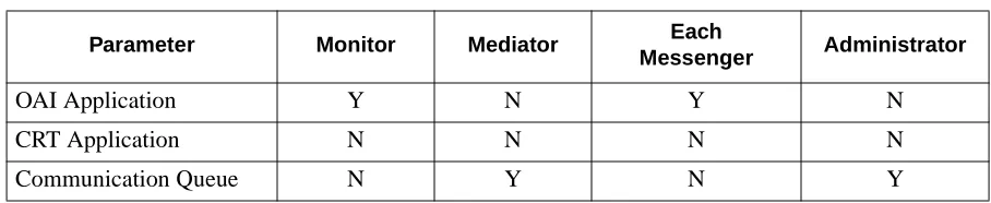
When adding UCD-XL to the APM Application Configuration file, characterize each of its components as follows:
Table 3-1 UCD-XL Component Characteristics
Parameter Monitor Mediator Each
Messenger Administrator
OAI Application Y N Y N
CRT Application N N N N
Parameter definitions:
• OAI Application Indicates whether or not (Yes or No) this com-ponent communicates with the NEAX2400 using OAI processes.
• CRT Application Indicates whether or not (Yes or No) this com-ponent runs on the same screen as the APM, rendering the APM temporarily inaccessible. •
Communication Queue
Indicates whether or not (Yes or No) thisnon-OAI component needs an IPC queue to com-municate with other processes.
Primary Configuration Parameters
On the APM’s Application Configuration Entry screen, make the entries shown below to the parameters indicated for each component.
The component names shown below are examples only. Queue key values may be changed if they conflict with another application.
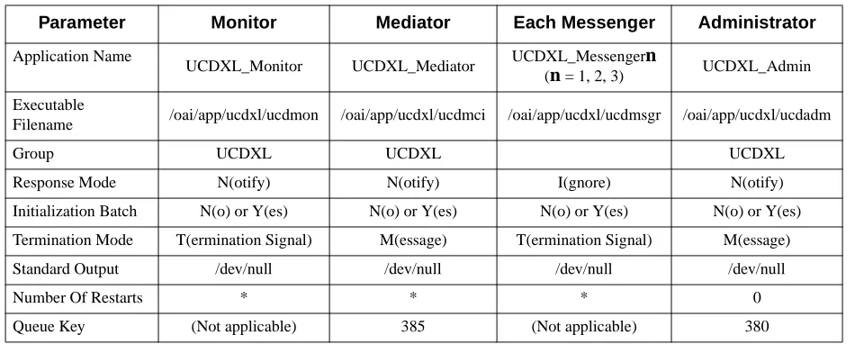
Parameter definitions:
• Application Name Specifies the name to be displayed in the APM menus and identifies the component. This name is displayed as entered. Lower case letters and
punc-Table 3-2 Primary Configuration Parameters
Parameter Monitor Mediator Each Messenger Administrator
Application Name
UCDXL_Monitor UCDXL_Mediator UCDXL_Messengern
(n = 1, 2, 3) UCDXL_Admin
Executable
Filename /oai/app/ucdxl/ucdmon /oai/app/ucdxl/ucdmci /oai/app/ucdxl/ucdmsgr /oai/app/ucdxl/ucdadm
Group UCDXL UCDXL UCDXL
Response Mode N(otify) N(otify) I(gnore) N(otify)
Initialization Batch N(o) or Y(es) N(o) or Y(es) N(o) or Y(es) N(o) or Y(es)
Termination Mode T(ermination Signal) M(essage) T(ermination Signal) M(essage)
Standard Output /dev/null /dev/null /dev/null /dev/null
Number Of Restarts * * * 0
• Initialization Batch Indicates whether or not (Yes or No) the compo-nent is to be initialized automatically when the OAI system is initialized.
• Termination Mode Indicates how the APM is to notify the compo-nent to terminate.
• Standard Output Designates the file into which component output is redirected.
• Number of Restarts Indicates how many times the APM may restart the component after it terminates erroneously. • Queue Key Indicates the unique number of the queue that is
to be assigned to the component.
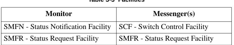
Facilities
According to instructions in the APM Operations Manual, designate the following NEAX2400 facilities for UCD-XL Monitor and all UCD-XL Messengers, using the Facilities command on the APM Configuration Entry screen.
OAI Configuration
Using the OAI-Conf command on the Application Configuration Entry screen, select the entry shown for each of the following parameters required by the Monitor component. Use the instructions provided for this option in the APM Operations Manual.
Note: Italicized entries may be changed.
Table 3-3 Facilities
Monitor
Messenger(s)
Table 3-4 Monitor Parameters
Parameter Entry Description
Database Name #1
/oai/db/cur/ucdgrps Filename of the UCD-XL Group Identification Database.
Database Name #2 /oai/db/cur/ucdports Filename of the UCD-XL Port Assignment Database. Timeout Value #1
30
Default frequency of port inspection, in minutes. This may be overridden by the value given for a group in the Group Identification Database (see page 42). If the group’s value is 0 and the default value is 0, inspections of that group will not occur.
Timeout Value #2 0 Unused by Monitor.
Tenant Number
0 Specifies the number of the tenant that UCD-XL
Monitor serves. (0 means all ports and tenants) Source Link Name
OAI1TCP
Identifies the port on the source side of the
communication link; entry should correspond to a link name in the APM system configuration file.
Destination Link Name
PBX1TCP
Identifies the port on the destination side of the communication link; entry should correspond to a link name in the APM system configuration file.
Association Recovery
15 Interval, in seconds, UCD-XL Monitor waits before
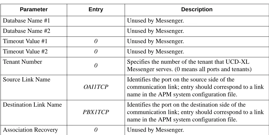
Using the OAI-Conf command on the Application Configuration Entry screen, make the entry shown for each of the following parameters required by each Messenger component; each Messenger has the same values for its parameters. Use the instructions provided for this option in the APM Operations Manual.
Note: Italicized entries may be changed.
User-Defined Parameters
Make the entries shown for each of the following user-defined parameters (UDPs) by using the UserDefined command on the APM’s Configuration Entry screen (for the Mediator and Administrator components), or on the OAI Configuration screen (for the Monitor and Messenger components).
Note: Italicized entries may be changed. The format X(xxxxx) indicates that only the first letter is significant.
Table 3-5 Messenger Parameters
Parameter Entry Description
Database Name #1 Unused by Messenger.
Database Name #2 Unused by Messenger.
Timeout Value #1 0 Unused by Messenger.
Timeout Value #2 0 Unused by Messenger.
Tenant Number
0 Specifies the number of the tenant that UCD-XL
Messenger serves. (0 means all ports and tenants) Source Link Name
OAI1TCP
Identifies the port on the source side of the
communication link; entry should correspond to a link name in the APM system configuration file.
Destination Link Name
PBX1TCP
Identifies the port on the destination side of the communication link; entry should correspond to a link name in the APM system configuration file.
Monitor
User-defined
Parameters
Make the following entries on the OAI Configuration screen. Italicized entries can be changed.
Table 3-6 Monitor User-defined Parameters
User Defined Entry Definition
#1 /oai/db/cur/ucdani
Pathname of the ANI Pattern Database. This is required only if you desire the distribution of calls based upon their ANI data. Otherwise, leave this parameter blank. #2 (blank) This parameter is no longer being used.
#3 A(ll stats)
Type of statistics collected. Select one of the following entries:
A(ll stats): All call activity, per group and per port. M(ajor): Call activity per group, including
incoming call count, abandoned call count, queued call count, and average and maximum durations of queued calls.
N(one): Do not collect statistics.
#4 H(ourly)
Statistics collection frequency. Select one of the following entries:
H(ourly): Statistics are collected at the top of the hour, each hour.
D(aily): Statistics are collected at midnight, each day.
If no statistics will be collected, this parameter is irrelevant.
#5 /oai/app/data/ucdxl Directory of the statistics file, trace file, and report file.
#6 /oai/app/ucdxl/ucdrptr Filename of the Reporter process, which stores the statistics and trace data in the statistics directory.
#7 20
Messenger
User-defined
Parameters
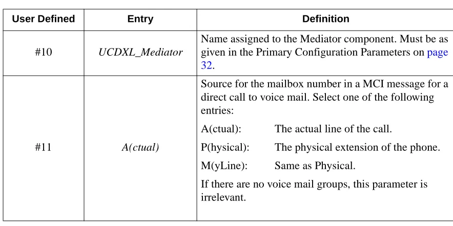
Make the following entries on the OAI Configuration screen. Italicized entries can be changed.
#10 UCDXL_Mediator
Name assigned to the Mediator component. Must be as given in the Primary Configuration Parameters on page 32.
#11 A(ctual)
Source for the mailbox number in a MCI message for a direct call to voice mail. Select one of the following entries:
A(ctual): The actual line of the call.
P(hysical): The physical extension of the phone. M(yLine): Same as Physical.
If there are no voice mail groups, this parameter is irrelevant.
Table 3-6 Monitor User-defined Parameters
User Defined Entry Definition
Table 3-7 Messenger User-defined Parameters
User Defined Entry Definition
#1 UCDXL_Monitor
Name assigned to the Monitor component. Must be the same as in the Primary Configuration Parameters on
page 32.
#2 125
Shared memory key. Can be changed if it conflicts with another application, but must be the same as in the Monitor’s configuration.
#3 165
Mediator
User-defined
Parameters
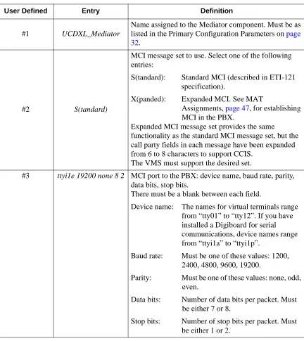
Make the following entries on the APM Configuration Entry screen. Italicized entries can be changed.
Table 3-8 Mediator User-defined Parameters
User Defined Entry Definition
#1 UCDXL_Mediator
Name assigned to the Mediator component. Must be as listed in the Primary Configuration Parameters on page 32.
#2 S(tandard)
MCI message set to use. Select one of the following entries:
S(tandard): Standard MCI (described in ETI-121 specification).
X(panded): Expanded MCI. See MAT
Assignments, page 47, for establishing MCI in the PBX.
Expanded MCI message set provides the same
functionality as the standard MCI message set, but the call party fields in each message have been expanded from 6 to 8 characters to support CCIS.
The VMS must support the desired set.
#3 ttyi1e 19200 none 8 2 MCI port to the PBX: device name, baud rate, parity,
data bits, stop bits.
There must be a blank between each field.
Device name: The names for virtual terminals range from “tty01” to “tty12”. If you have installed a Digiboard for serial communications, device names range from “ttyi1a” to “ttyi1p”.
Baud rate: Must be one of these values: 1200, 2400, 4800, 9600, 19200.
Parity: Must be one of these values: none, odd, even.
Data bits: Number of data bits per packet. Must be either 7 or 8.
#4 ttyi1f 19200 none 8 2
MCI port to the VMS: device name, baud rate, parity, data bits, stop bits.
Device name: The names for virtual terminals range from “tty01” to “tty12”. If you have installed a Digiboard for serial communications, device names range from “ttyi1a” to “ttyi1p”.
Baud rate: Must be one of these values: 1200, 2400, 4800, 9600, 19200.
Parity: Must be one of these values: none, odd, even.
Data bits: Number of data bits per packet. Must be either 7 or 8.
Stop bits: Number of stop bits per packet. Must be either 1 or 2.
#5 /oai/app/ucdxl/reader Filename of the Reader process, which receives MCI messages from the PBX and VMS ports.
#6 UCDXL_Monitor Name assigned to Monitor component. Must be as given
in the Primary Configuration Parameters on page 32.
#7 4
Number of digits, 4 maximum, comprising an office code. Specify a value other than 0 only if your PBX network uses office codes and you do not want them in the MCI messages that UCD-XL will send to a VMS.
#8 not used N/A
#9 not used N/A
#10 not used N/A
#11 not used N/A
#12 not used N/A
#13 not used N/A
#14 t (trace)
Establishes a trace of MCI messages being received from and transmitted to the VMS and PBX by the Mediator. MCI messages will be displayed in ASCII form, with spaces replaced by underscores, in the APM log and in the APM Status Window. This feature should only be used to validate MCI communication among the PBX, UCD-XL, and VMS. Be sure to turn off the trace, by terminating the Mediator and clearing UDP #14 (or setting it to “no trace”), before establishing the normal operation of UCD-XL.
Table 3-8 Mediator User-defined Parameters
Administrator
User-defined
Parameters
Make the following entries on the APM Configuration Entry screen. Italicized entries can be changed.
Table 3-9 Administrator User-defined Parameters
User Defined
Entry
Definition
#1 UCDXL_Admin
Name assigned to the Administrator component. Must be as given in the Primary Configuration Parameters on
page 32.
#2 tty12
Device name of Administrator’s terminal. Cannot be the device name of the current terminal.
The names for virtual terminals range from “tty01” to “tty12”. If you have installed a Digiboard for serial communications, device names range from “ttyi1a” to “ttyi1p”.
Note: Communication characteristics for the Administra-tor’s terminal are fixed at 9600 baud, no parity, 8 data bits, and 1 stop bit.
#3 ansi_a
Type of Administrator’s terminal. Select one of the following entries:
ansi_a: use this for virtual terminals. vt100: use this for dumb terminals.
#4 adm Administrator’s password, not more than 10 characters.
Do not use blanks.
#5 UCDXL_Monitor
Name assigned to the Monitor component. Must be as listed in the Primary Configuration Parameters on page 32.
#6 /oai/app/data/ucdxl Path to the statistics file, trace file, and report file.
#7 /oai/db/cur/ucdgrps Filename of the UCD-XL Group Identification Database.
#8 lp
Print command.
Can be a UNIX script. When printing, UCD-XL appends the appropriate filename to the end of the command.
Chapter 4
Database Requirements
UCD-XL requires two databases that are constructed through the APM: the Group Identification Database, and the Port Assignment Database. A third database is optional--the ANI Pattern Database. Database creation involves the following 5-step process for each required database:
1. Create Master Definition File - This step involves creating the master defini-tion file that defines the fields in the master database file.
Note: If you have installed UCD-XL as described on page 11, this step has been done for you.
2. Build Master Database File - This step involves entering data into the master database fields that were just defined in the master definition files in Step 1. This creates the records of the master database file.
3. Create Application Definition File - In this step, a definition file is created for each of the UCD-XL databases. This file defines the formats by which data from the corresponding master file are to be converted to meet the needs of UCD-XL.
Note: If you have installed UCD-XL as described on page 11, this step has been done for you.
4. Process Application Database - In this step, the records of the Application Da-tabase file are created. Data is drawn from the master daDa-tabase and converted to the formats specified in the corresponding application definition file.
5. Install Application Database - In this step, the UCD-XL components (if run-ning) are notified so that they can read the appropriate application database. Normally, the Master Definition file and the Application Definition file are provided when the UCD-XL software is installed. In this case, only steps 2, 4, and 5 above are necessary.
Instructions
The information required for all of the UCD-XL databases is provided in table form on the following pages. Using this information plus the procedural instructions provided in the APM Operations Manual, enter the Database Administration option on the APM System Administration Menu. Then build the UCD-XL databases, one at a time. Any messages displayed during these steps are addressed in the Process and Error Messages chapter of the APM Operations Manual.
Group
Identification
Database
The Group Identification Database identifies the groups that the application will manage. The name of the Group Identification master definition file must be
ucdgrps_m, and the name of the application definition file must be ucdgrps.
Note: The order of the fields in the application definition file differs from that in the master definition file. The “pos” column in the following table indicates the cor-rect positions of the fields in the application definition file.
Table 4-1 Group Identification Database Field
Descrip-tion
Master Definition File Application Definition File
Master Database
Type Size Min. Value Max. Value Pos Data Type Typical
Entry
Group ID N 3 1 999 1 short int 1
Group
Name A 24 3 ASCII Executive
Pilot
Number N 5 0 99999 4 long int 59432
Tenant
Number N 3 1 255 2 short int 1
Announce ment Message Number
N 3 0 58 5 short int 0
Voice Mail?
(Y or N) A 1 N 9 ASCII Y
Check ANI? (Y or N)
A 1 N 10 ASCII N
Call
Distribution Method
A 10 Round
Robin 8 ASCII
Round Robin
Port Inspection Period
N 2 0 60 7 int 15
Field Definitions:
• Group ID - A number that identifies the UCD group. The Group ID must
be unique. Records are ordered by group ID.
• Group Name - An alphanumeric string that identifies the UCD group in
reports.
• Pilot Number - The monitored number which a caller must dial in order
to access one of the ports in the group, or to be routed based upon ANI data (if the “Check ANI” flag is set). It must be assigned in the PBX using the AMNO command (see page 47). A non-zero pilot number must be unique among all groups.
Note: This value may be 0 if the group is only used as the destination of ANI-distributed calls as specified in the ANI Pattern Database.
• Tenant Number - A number that identifies the tenant to which all ports
in the group belong.
• Announcement Message Number - A number that identifies the
an-nouncement a caller will hear if all ports are busy. This applies only when an announcement package is used to handle call overflow. More than one group may be assigned the same announcement message number. If this value is 0, then calls to the applicable group will not be connected to an announcement message upon overflow. (The caller hears ringback tone while queued.) This announcement message number must be assigned in the PBX using the AADT command (see page 47).
• Voice Mail? (Y or N) - Is the group intended for use with a voice mail
system? Answer “Y” for yes or “N” for no. (Default is “N”.) If the answer is “Y”, then the Mediator component is required.
• Check ANI? (Y or N) - Shall calls to the pilot number of this group be
distributed to the proper group (not necessarily this one) based upon their ANI data? Answer “Y” for yes or “N” for no. (Default is “N”.) If the an-swer is “Y”, then the ANI Pattern Database is required and it is not nec-essary for this group to have any ports assigned to it.
• Call Distribution Method - The method by which a call will be
distrib-uted to a port within the group. Select one of the following entries (only the first letter is necessary):
RoundRobin - Calls are connected to the next idle port in a group that
follows the previous port used.
TopDown - Calls are connected to the lowest-numbered idle port in a
group.
Field Definitions (Continued):
• Port Inspection Period - Frequency of inspection of the group’s ports, in
minutes. If this value is 0, the default frequency configured for the Moni-tor component is used. If that value is 0 also, no inspection is performed. • Announcement Period - The number of seconds to wait between
at-tempts at connecting a queued call to an announcement message. If this value is 0, only one attempt is made. This value is irrelevant if the an-nouncement message number (above) is 0.
Port Assignment
Database
The ports of each group are identified in the Port Assignment Database. The name of the Port Assignment master definition file must be ucdports_m, and the name of the application definition file must be ucdports.
Field Definitions:
• Port Extension - A unique numeric value assigned to exactly one group.
The extension must be defined in the PBX. All extensions must belong to the same tenant. The records are ordered by extension.
• Group ID - A number that identifies the UCD group. This group must be
defined in the Group Identification Database.
Warning:A port extension should not be a UCD pilot number in the PBX. When UCD-XL connects a call to such an extension, the PBX will send its own MCI message, which may conflict with the one that UCD-XL generates, causing a VMS to re-spond to the call incorrectly
.
Table 4-2 Port Assignment Database
Field Description
Master Definition File
Application Definition
File
Master Data-base
Type Size Min. Value Max. Value Data Type Typical Entry
Port
Exten-sion N 5 100 99999 long int 3600
ucdani.
Field Definitions:
• ANI Pattern - A string of characters that represents a specific ANI
num-ber or a set of ANI numnum-bers. A pattern may consist of a combination of digits and/or asterisks, or it may be a special word (see below). An asterisk is a “wild card” character, representing any digit or set of digits. For ex-ample, “214*” matches any call originating in the 214 area code; “*” matches any call with ANI. If an asterisk is in the middle of a pattern (e.g. 21455*0000), it matches a single digit only.
There are three special patterns, identified by a single word (upper or low-er case):
DEFAULT - This represents any call that does not have ANI data or
whose ANI does not match any other pattern in the database. There must be a record in the ANI Pattern Database that specifies the
DE-FAULT pattern.
FOREIGN - This represents any call originating from outside the
North American Numbering Plan; i.e. ANI greater than 10 digits.
INTERNAL - This represents any call originating within the PBX
net-work; for example, an extension.
Note: The format of an ANI number is assumed to be a 3-digit area code followed by a 3-digit exchange and a 4-digit extension, as defined by the North American Num-bering Plan. The field is larger to accommodate international calls in the future.
• Primary Group - ID of the group to which a call will be usually directed
if its ANI number matches the specified pattern. This value must corre-spond to a record in the Group Identification Database.
Note: This group does not have to be the one whose pilot number was called, nor does it have to be one that has its “Check ANI” flag set.
• Overflow Group - ID of the group to which a call will be directed if its
ANI number matches the specified pattern and there are no ports available in the primary group. A non-zero value must correspond to a record in the Group Identification Database. If this value is zero or the overflow group has no available ports, the call will be handled in a manner dictated by the
Table 4-3 ANI Pattern Database
Field Description
Master Definition File
Application Definition
File
Master Data-base
Type Size Min. Value Max. Value Data Type Typical Entry
ANI Pattern A 16 default ASCII 214*
Primary
Group N 3 1 999 short int 16
Overflow
overflow method for the primary group (i.e. connected to an announce-ment message or simply queued).
Chapter 5
MAT Assignments
This guide assumes that data settings which affect the operation of all OAI software on a system-wide basis have already been assigned on the NEAX Maintenance Administration Terminal (MAT). Such settings include, for instance, system index values and assignment of Interface I/O Port Data in the Interface Processor (IP). For more information about these system data settings, and for instructions in making the following UCD-XL settings, consult the OAI System Manual for the NEAX2400 IMS.
AADT Command (Assignment of Announcement/Dictation Trunk):
This MAT command sets up the announcement message number, and is rele-vant only when a group is assigned an announcement message number (see
page 36).
AMNO Command (Assignment of Monitored Numbers):
Whenever a call comes into a monitored number, UCD-XL is informed. Use this MAT command to assign the monitored numbers that represent the pilot numbers for the groups in the Group Identification Database (see page 42).
ARNP2 Command (Assignment of Reverse Numbering Plan 2):
To set an office code, set RT to 0 and set ACC to the desired office code, max-imum of 4 digits. To delete an office code, set RT to 0 and respond Y at the prompt.
ASHU Command (Assignment of Station Hunting - UCD):
This MAT command defines the UCD group to which a monitored number de-grades. This should be a subset of a group defined in UCD-XL.
Note: The pilot number should not be a member of the Port Assignment Database. ASYD Command (Assignment of System Data):
Assign SYS (1), INDEX 246, BIT 3 the value of 1 for MCI expansion service. This is relevant only if using Expanded MCI.
Assign SYS (1), INDEX 28, BIT 5 to provide MWL control, and SYS (1), IN-DEX 29, BITS 0 - 5 to specify the MCI port for either standard or expanded MCI service.
Assign SYS(1), INDEX 240, BIT 5 the value of 1 to provide across CCIS (and hence to UCD-XL) the physical extension (my line) of a call from a remote PBX. If this value is 0, the actual extension (such as a virtual line) of the call is provided.
Chapter 6
Initialization and Termination
Initialization
UCD-XL must be initialized through the APM Operations Menu according to instructions provided in the APM Operations Manual. Although each of the configured components is initialized individually, the Monitor must be initialized prior to or in conjunction with any one or more Messengers. Although the Messenger(s) cannot function unless the Monitor is already running, the Administrator and Mediator function independently of the Monitor. When the Monitor is initialized, it will wait in STANDBY mode for at least one Messenger to start up before being capable of processing calls.
Initializing the Administrator brings up the logon screen on the Administrator’s terminal.
The Mediator must be initialized to provide MCI communication with the VMS. As an alternative, some or all of the UCD-XL components may be configured (by using the “initialization batch” field) to start automatically when the APM initializes the OAI system. See page 32.
Termination
Termination of any or all of the components of UCD-XL may be performed at any time according to instructions provided in the APM Operations Manual. If the Monitor is terminated, all Messenger components terminate automatically. If Mediator is terminated, MCI communication with the VMS ceases.
If the last Messenger is terminated, Monitor goes into STANDBY mode, and cannot process calls.
When Monitor is terminated, UCD-XL call processing ceases; Mediator and Administrator can still be running, but the Administrator is unable to provide a trace of call activity.