Issue 2
DIGITAL FEEDBACK ELIMINATOR
V-5335611
by
PagePac
®INTRODUCTION
The V-5335611 is designed to eliminate acoustic feedback. When a page is made, the message is digitized and saved. Upon completion of the live page, the message is released for broadcast over system speakers. (While this page is being broadcast, another page can be recorded). This eliminates the offensive squeal of feedback com-monly produced by telephones or microphones when making a page.
SPECIFICATIONS
FEATURES
• Comes with Power Supply • Automatic Gain Control (AGC) • Adjustable VOX Sensitivity • Two Input Channels:
Switch selectable for primary and priority or dual channels with equal priority
Both inputs are switch selectable for loop start (600 Ohms) or VOX activation
• Two Audio Outputs:
Loop Out (600 Ohms) to Page Controller Line Level (8 Ohms) to Amplified Speakers or Amplifier
• Background Music Input (adjustable) • Three Normally Open Output Relays:
Play, Record, Busy
• Four LED Indicators: Power On, Play, Record, and Busy
• Dip Switch Programmable • Message Cancelling
• Easy to install in new or existing systems • Solid State, DSP Storage and Playback • High Fidelity CD Quality Sound Reproduction
Access
• Loop Start Trunk Port of PBX • C. O. Line Position of Key System
• Page Port
• Line Level Audio Feed
Nominal Specifications
Input Impedance: 600 Ohms
Input Level: -10 dBm
Loop Out Output Impedance: 600 Ohms Line Level Output Impedance: 8 Ohms Output Level: -10 dBm (nominal) VOX Sensitivity: -20 dBm to -35 dBm Release time after last sensed audio: 3 seconds Maximum duration of recorded page:60 seconds
Maximum number of stored pages: 2 Primary/Priority Mode
4 Call Stacker Mode Frequency Response:
Page: 80 Hz to 7 kHz
Background Music: 50 Hz to 17 kHz
Nominal Power Requirements
-24VDC, 500mA, “B” BatteryDimensions/Weight
• 10.3"H x 7.8"W x 2.2"D(26.2cm x19.8cm x 5.6cm) • 2.6 lbs. (1.2 kg)
Environment
• Temperature: 0 to 40°C (32 to 104°F)
FCC Notice
This equipment has been tested and found to comply with the limits for Class A digital devices, pursuant to Part 15 of FCC Rules. These limits are designed to provide reasonable protection against harmful interference when the equipment is operated in a commercial environment. This equipment generates, uses, and can radiate radio frequency energy and, if not installed and used in accordance with the instruction manual, may cause harmful interference to radio communica-tions. Operation of this equipment in a residential area is likely to cause harmful interference in which case the user will be required to correct the interference at his own expense.
INSTALLATION/CONNECTIONS
Cabling
It is recommended that Category 3 or 5 twisted pair telephone wire be used for all wiring connec-tions to the V-5335611. A screw type connector strip is provided to allow connection of all wiring to the V-5335611.
Mounting
The V-5335611 is wall mountable using ½" screws.
Terminal Connection Access
NOTE: Remove the small right side panel to access all controls and terminations. To remove panel, loosen the two screws holding the panel in place and lift panel away from the board.
Audio Input
Line level or low level source. Do not connect to 70V or Voice-Coil audio output.
Setting Program Dip Switches
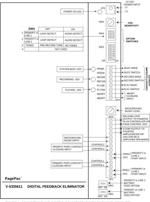
There are controls and switches on the board for programming the options of the V-5335611. Refer to Figure 1 (page 5) for location of switches and controls.
(Tip1/Ring1)
Primary or Call Stacker Line 1 Input
The primary input is the path normally used to access the unit for recording and playback of a page.(Tip2/Ring2)
Priority or Call Stacker Line 2 Input
Priority access will override primary input activity.
Control 1 Input (for Primary Port or Line 1)
Use External Dry Contact Closure to activate "Begin Recording" sequence. (Also see Note for SW4-3 Switch).Control 2 Input (for Priority Port or Line 2)
Use External Dry Contact Closure to activate "Begin Recording" sequence. (Also see Note for SW4-3 Switch).BGM Input
External low-level music source (Ex: V-2952). Access Method Switch Settings
Loop Start Trunk Port SW1 ON SW4-1 OFF
Key System C.O. Line Key SW1 ON SW4-1 OFF
Stand Alone Telephone Set SW1 ON SW4-1 OFF
Page Port w/Contact Closure SW1 OFF SW4-1 OFF
Page Port w/o Cont. Closure SW1 OFF SW4-1 ON
Valcom Page Ctrl. Output SW1 OFF SW4-1 ON
V-5335700 (PagePal) Output using C.C.
SW1 OFF SW4-1 ON
Access Method Switch Settings
Loop Start Trunk Port SW2 ON SW4-2 OFF
Key System C.O. Line Key SW2 ON SW4-2 OFF
Stand Alone Telephone Set SW2 ON SW4-2 OFF
Page Port w/Contact Closure SW2 OFF SW4-2 OFF
Page Port w/o Cont. Closure SW2 OFF SW4-2 ON
Valcom Page Ctrl. Output SW2 OFF SW4-2 ON
V-5335700 (PagePal) Output using C.C.
Line Out
8 Ohm output connects to PagePac® Amplifier Inputs, Self-Amplified Valcom Speakers or other audio devices.
NOTE: Connect “Play”contact closure to C1 and Ground of amplifier when using PagePac® Ampli-center. Set amplifier to Dry Loop 600 Ohms.
Loop Out
Connect to the telephone system input of a multi-zone controller, the 600 Ohm output connects to the PagePac® Plus Controller . Set controller to Loop Start.
R77 Adjustment Pot
Adjusts Background Music Output Level.
Abort
Option 1: To abort a message during “Play Sequence”, use an External Contact Closure input to manually stop message broadcasting.
Option 2: To abort a message during "Record Sequence", press any number on the dial pad of the telephone.
Contact Closure Outputs
(PLAY) PLYSW and PLYMK
Normally Open Contact Closure output that is closed while message plays.
(RECORD) RECSW and RECMK
Normally Open Contact Closure output that is closed while message records.
(BUSY) PRISW and PRIMK
Normally Open Contact Closure output that is closed when unit cannot accept any more pages.
All Dip Switches (OFF - Left) (ON - Right)
SW1: Primary Port or Line 1 Battery Feed
SW2: Priority or Line 2 Port Battery Feed
SW3 The 8-position dipswitch provides:
SW3-1: DTMF Signalling Options
SW3-2, SW3-3: Number of digits to receive before recording announcement.
SW3-4: Priority Port Mode
SW3-5: Message Playback Control
SW3-6, SW3-7: Pre-Page Alert Tones
SW3-8: Inter-Page Timing
No battery feed supplied to primary port OFF
Battery feed supplied to primary port ON
No battery feed supplied to priority port OFF
Battery feed supplied to priority port ON
No DTMF signal (single zone) OFF
DTMF signal accepted (multi-zone) ON
1 digit SW3-2 OFF SW3-3 OFF
2 digits SW3-2 ON SW3-3 OFF
3 digits SW3-2 OFF SW3-3 ON
4 digits SW3-2 ON SW3-3 ON
Records primary and priority pages, priority page broadcasts first
OFF
Priority page broadcasts in real time. Primary page in progress is recorded and is broadcast after priority page.
ON
Play message once OFF
Play message twice ON
No Tone SW3-6 OFF SW3-7 OFF
Single Tone SW3-6 ON SW3-7 OFF
Dual Tone SW3-6 OFF SW3-7 ON
Quad Tone SW3-6 ON SW3-7 ON
1 second between pages OFF
SW4 The 4-position dipswitch provides:
SW4-1: Primary or Line 1 Page Access
SW4-2: Priority or Line 2 Page Access
SW4-3: Pre-Record Tone (Enable/Disable)
NOTE: This option is effective only when the input is set for Loop Detect (SW4-1 OFF).
SW4-4: Normal or Call Stacker Mode
Other Switches and Controls
SW5: VOX Sensitivity - sets threshold for detec-tion of audio on the primary and priority ports. Turn clockwise to increase sensitivity.
LED Indicators
PLAY: Illuminates when announcement is playing.
RECORD: Illuminates during recording of the announcement.
BUSY: Illuminates if, for any reason the unit cannot accept any more pages.
POWER: Illuminates when -24VDC and GND is applied to the unit.
TECHNICAL ASSISTANCE
When calling, have a VOM and a telephone test set available and call from the job site. Call (540) 427-3900 and ask for PagePac Technical Support, or call (540) 427-6000 for Valcom 24-hour Auto-mated Support or visit our websites at
http://www.pagepac.com and www.valcom.com.
Should repairs be necessary, attach a tag to the unit clearly stating company name, address, phone number, contact person, and the nature of the problem. Send the unit to:
Valcom, Inc. PagePac® Repair Dept.
5614 Hollins Road Roanoke, VA 24019-5056
Loop Detect OFF
Audio Detect (VOX) ON
Loop Detect OFF
Audio Detect (VOX) ON
Normal (3 sec. delay of “Ready to Record” tone and “Recording Sequence”)
OFF Enable
No tones are issued when “Recording Sequence” is activated. Allows imme-diate “Record Activation”.
ON Disable
2 Inputs - Primary and Priority OFF
2 Inputs will function as Call Stacker ON
SW5 LEVEL SW5 LEVEL
0 -20dBm 8 -28dBm
1 -21dBm 9 -29dBm
2 -22dBm A -30dBm
3 -23dBm B -31dBm
4 -24dBm C -32dBm
5 -25dBm D -33dBm
6 -26dBm E -34dBm
On 1 2 3 4 SW4
SW3 12 3 4 5 6 7 8 Off JP3 SW5 JP2 R77 JP1 SW2 SW1 OFF ON
OFF ON
V-5335611 DIGITAL FEEDBACK ELIMINATOR
-24 VDC POWER INPUT (-) (+) VOX SENSITIVITY OPTION SWITCHES PRIMK PRISW RECMK RECSW PLYMK PLYSW ABORT ABORT BACKGROUND MUSIC LEVEL CONTROL2 CONTROL2 RING2 TIP2 RING1 TIP1
PRIORITY or LINE 2 BATTERY
FEED OPTION PRIMARY or LINE 1 BATTERY FEED OPTION
FIGURE 1: CONNECTIONS AND CONTROLS (ACCESSIBLE WITH SIDE PANEL REMOVED)
PRIORITY or LINE 2 PORT INPUT PRIMARY or LINE 1 PORT INPUT POWER ON LED
SYSTEM BUSY LED
RECORDING LED
PLAYING LED
BACKGROUND MUSIC INPUT PRIORITY PORT CONTACT CLOSURE INPUT
600 OHM LOOP OUTPUT TO PAGEPAC PLUS CONTROLLER OR PAGE CONTROL UNIT 8 OHM OUTPUT TO PAGEPAC AMPLICENTER OR VALCOM SELF-AMPLIFIED SPEAKERS SW4 PRIMARY or LINE 1 PRIORITY or LINE 2
LOOP DETECT AUDIO DETECT LOOP DETECT AUDIO DETECT
NOT USED ON OFF 1 2 3 4
TONES PRE-RECORD TONE NO TONES
CONTROL1 CONTROL1 PRIMARY PORT CONTACT
AUDIO T INPUT R
C1 GROUND
V-5335611
OUTPUT 70V Speakers LINE OUT
LINE OUT PLYSW PLYMK
FIGURE 2 - SIMPLIFIED BLOCK DIAGRAM OF TYPICAL CONFIGURATIONS
(Power connections not shown) AMPLIFIER
PAGE PORT ACCESS
TIP1 RING1 CONTROL1 CONTROL1
V-5335611
Page Port
Contact Closure (optional) TELEPHONE
SYSTEM
SINGLE ZONE AUDIO OUTPUT
PAGEPAC®AMPLICENTER
PAGEPAC® PLUS CONTROLLER
TIP1 RING1
V-5335611
Multi-Zone Control Unit VALCOM T
R Tip Ring
Zone Output TELEPHONE
SYSTEM
600 Ohm Audio Out PAGE PAL T
R
TIP1 RING1
V-5335611
Tip Ring C. O. LINE, CENTREX OR PABX STATION LEVEL ACCESS
C.C.Output CONTROL1 CONTROL1
STATION LEVEL ACCESS
V-5335611
600 OHM LOOP OUTPUT TIP1
RING1
Telephone System Input
70V Speakers connect to PagePac Plus
zone outputs
Generic Amplifier
V-5335611
TIP1 RING1
GENERIC AMPLIFIER ACCESS V-5335611
TIP1 RING1
LOOP START ACCESS
LOOP START TRUN K PORT, KEY SYSTEM CO LINE PORT OR STAND ARD TELEPHONE SET
TYPICAL ACCESS CONFIGURATIONS
TYPICAL OUTPUT CONFIGURATIONS
up to 150 Valcom Amplified Speakers
OR
Contact Closure if needed LINE OUT