© 2017, IRJET | Impact Factor value: 5.181 | ISO 9001:2008 Certified Journal | Page 5664
HYDROGEN AS A PETROL ADDITIVE IN 4 STROKE I C ENGINE
Ritesh Dhanotiya
1, Nitesh Kumar
2, Naveen S patil
3, Nikhil Kumar C
4, T Venkate Gowda
5,
Anil Kumar P R
61,2,3,4,
U. G. Students, Department. Of Mechanical Engineering, Sapthagiri College of Engineering, Bangalore,
Visvesvaraya Technological University, Belagavi, Karnataka, India
5, 6
Assistant Professors, Department of Mechanical Engineering, Sapthagiri College of Engineering,
Bangalore, Visvesvaraya Technological University, Belagavi, Karnataka, India
---***---Abstract
- Brown’s gas (HHO) has recently been introducedto the auto industry as a new source of energy. The present work proposes the design of a new device attached to the engine to integrate an HHO production system with the gasoline engine. The proposed HHO generating device is compact and can be installed in the engine compartment. This auxiliary device was integrated and tested on a gasoline engine. Pulsar DTSi 150cc four stroke single cylinder engine was procured for the project. Belt rope dynamometer, mounting frames and experiment setup were designed and fabricated. HHO gas kit was installed with engine. Performance analysis and emission analysis has been done by using Petrol and Petrol-HHO separately on engine. It has been found that around 10% reduction in fuel consumption is achieved by using petrol-HHO and appreciable amount of reduction in emission of pollutants such as CO, unburned hydro carbons and CO particularly during the idle 2 condition
1. INTRODUCTION
This paper illustrates what is the effect of the partial inclusion of the HHO gas into the conventional S.I engine along with the petrol. As we know that current global economy faces problems in the fossil fuels and fossil fuels end in the nearest future. Another reason is that, these fossil fuels are also harmful for the environment. It affects the protection layer of the earth i.e. Ozone layer as well as global warming effect & greenhouse effects. Internal combustion engine in which the combustion of fuel takes place inside the cylinder is known as I.C engine, the procedure of combustion are directly the motive fluid. Petrol & Diesel engine are the examples of this type, where the working substance is the product of combustion.
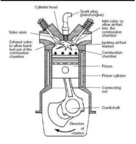
In this project we are using Spark Ignition Four Stroke I.C Engine. Basic working of Four Stroke Spark Ignition (S.I) Engine: Mainly, S.I engine working fuel is petrol which also termed as Gasoline. Petrol engine takes air and petrol mixture at required proposition which is taken into the intake manifold of an engine and ignited spark plug when the charge is compressed. The four stroke S.I engine was introduced in 1876 by Nicolaus August Otto. Four stroke S.I engine has 4-stroke means two revolution of crank-shaft in which piston comes from T.D.C to B.D.C in suction stroke & B.D.C to T.D.C in compression which one revolution of crankshaft. Then piston goes again T.D.C to B.D.C in
combustion stroke where spark plug ignite the airfuel mixture and again piston moves B.D.C to T.D.C in exhaust stroke to exhaust the flue gases generated in combustion of air-fuel mixture which is one another revolution. So total two revolution of the crankshaft.
[image:1.595.323.546.298.534.2]
Figure 1: Four-stroke Spark Ignition Engine
1.1
Desirable Properties of Good I.C Engine Fuel
High energy content per unit quantity of fuel.
Good combustion properties.
Availability in large quantities economically.
Free from fire hazards.
High stability with changes in temperature.
Low pollution
Easy to store & transport.
Products of combustion in gaseous form and noncorrosive.
2. THEORETICAL BACKGROUND
© 2017, IRJET | Impact Factor value: 5.181 | ISO 9001:2008 Certified Journal | Page 5665
to this reason there will be increasing in the mileage(kilometer per Litre). HHO gas is a supplement or as additive to conventional engine fuel system, it helps in combustion of the conventional engine fuels more efficiently & effectively. HHO gas is also called as Brown’s gas or oxy-hydrogen gas, it is water break in to two parts by the help of the electrolysis process of water, and hence it is two mole of hydrogen & one mole of oxygen.
2.1 Properties of HHO Gas
There are many unique and unusual properties that HHO Gas possesses. Below is a list of some of the properties.
Gas proves to be odorless, colorless and lighter than air.
In the production of HHO Gas, there is no evaporation process at all, the electric energy used being insufficient for evaporation.
The variable character of the energy content of HHO Gas is evidence that the gas has a unique structure with a chemical composition including bonds beyond those of valence type.
HHO Gas does not follow the fundamental PVT Law for gases.
HHO Gas demonstrates an anomalous adhesion to gases, liquids and solids. HHO Gas bonds to gaseous fuels (such as natural gas, magne gas fuel, and others) and also to liquid fuels (such as diesel, gasoline, liquid petroleum, and others).
Santilli describes the creation of the gaseous and combustible HHO from distilled water at atmospheric temperature and pressure via a process structurally different than evaporation or separation, which suggests the existence of a new form of water.
HHO is described to have the structure H-O-H where represents the new molecular bond and the conventional molecular bond. The transition from the conventional H-O-H configuration to the new H-O-H species is explained as being a change of the electric polarization of water caused by the electrolyzes.
2.2 HHO Gas Kit:
HHO gas kit is a device especially designed for the producing HHO gas by supplying 12 volts DC current. 12 volts DC current is supplied from the battery which has been already integrated with the vehicle this gas kit contains
HHO cell
Dryer
[image:2.595.346.519.87.250.2] Pulse modulator
Figure 2: HHO kit
2.3 HHO Cell
Two stainless steel electrodes are placed in the HHO cell and are connected with pulse with modulator circuit by external wiring. HHO cell is filled with electrolyte solution which contains mixture of water and electrolyte. The electrolytes used in the electrolytic solution are sodium hydroxide, potassium hydroxide and baking soda. Electrodes are dipped in the solution for passing the current.
2.
4 Dryer
The bubbler is simply a container half filled with water. HHO gas is fed to the bottom of the bubbler with a hose from your electrolyte tank and allowed to bubble through the water.
2.5 Pulse with Modulator
This electronic device is used to regulate the fluctuation of current and to protect the wires from the undesirable heat.
2.6 Measuring of Gas Flow Rate-Water
Displacement Test
© 2017, IRJET | Impact Factor value: 5.181 | ISO 9001:2008 Certified Journal | Page 5666
Table 1: flow rate of HHO gas at various current supply [image:3.595.57.264.202.418.2]3. EXPERIMENTAL SET-UP & ITS RESULT
Figure 3: An experimental set-up line diagram is shown as above
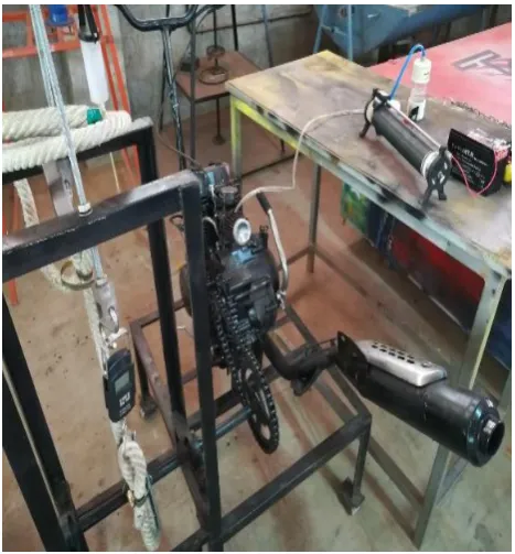
3.1 Construction
Petrol-HHO engine set up consists of four stroke pulsar 150-CC, single cylinder engine. The engine is attached to the bed of the Petrol-HHO engine set up by the help of fasteners. A 12 volt DC battery is fixed in the frame and the power from the battery is used to self-start and to power HHO gas kit. The output of HHO gas is connected to hose pipe after the air filter and before the carburetor.
Fuel is supplied from the petrol tank to burette with the help of valves and the fuel from the burette is supplied to the carburetor, from the carburetor the intake of petrol + HHO + air is supplied to the engine cylinder during the suction stroke.
During power stroke the crank shaft is driven by the piston and the crank shaft is coupled to the gear box by the help of clutch. A sprocket is attached at the output of the gear shaft. With the help of chain drive brake drum is driven by the gear shaft sprocket. Brake drum and sprocket is mounted on the shaft which is made up of MS.
The shaft is simply supported at the two ends by bush bearings. The bush bearings are mounted on the inverted V frame, top face of V frame slots are made for adjustment of
bush bearings in case of chain sprocket center distance is to be changed. One end of shaft is center drilled and the engine purpose of center drill is to take speed of output shaft by the help of tachometer. The flat belt is attached to the brake drum to apply the load by to and fro motion of lead screw while rotating the hand wheel. The applied load is shown in the spring balance. Two spring balances are attached to the belt one at the tight side and another at the slack side and tangential to the brake drum
.
[image:3.595.317.551.206.458.2]Figure 4: Following is the Experimental Set-up which we used to take experiments & result analysis
Table 2: Engine specification
Engine Type 4 stroke single cylinder natural air cooled
Bore*Stroke 58.5mm*56.40mm
Engine Displacement 149.01 cc
Maximum net power 14.09bhp @8500 rpm
Maximum net torque 12.76Nm @6500rpm
Compression ratio 9.5+/-0.5:1
3.2 Observation Table
Engine running on petrol without HHO kit Current(A) Flow rate(ml/min)
1.5 18
2.12 25.8
[image:3.595.303.545.525.673.2]© 2017, IRJET | Impact Factor value: 5.181 | ISO 9001:2008 Certified Journal | Page 5667
Table 3: Constant load and Varying speedEngine running with HHO kit
Table 4: Constant load and Varying speed
3.3 Results
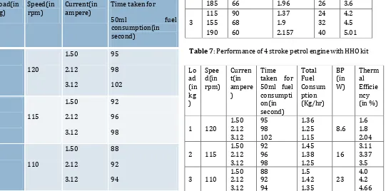
[image:4.595.43.584.437.705.2]Table 6: Performance of 4 stroke petrol engine without HHO kit (varying speed and varying load)
Table 7: Performance of 4 stroke petrol engine with HHO kit Load(in
kg) Speed(in rpm) Time taken for 50 ml fuel consumption(in second)
1 85 115 155 97 95 80 2 115 155 185 93 76 66 3 115 155 190 90 68 60 Load(in
kg) Speed(in rpm) Current(in ampere) Time taken for
50ml fuel
consumption(in second)
1 120
1.50 2.12 3.12 95 98 102
2 115
1.50 2.12 3.12 92 96 98
3 110
1.50 2.12 3.12 88 92 94
Table 5: Performance of 4 stroke petrol engine without HHO kit Load (in kg) Spe ed(i n rpm ) Time taken for 50ml of fuel consumpti on(in second) Total Fuel Consu mption (Kg/hr ) BP (in W) Therm al Efficie ncy (in %)
1 160 95 1.2 11.5 2.3
2 150 90 1.45 21.5 4.09
3 135 86 1.52 30 5.22
Lo ad (in kg ) Speed (in rpm)
Time taken for 50 ml fuel
consumptio n(in second)
Total Fuel Consumpti on (Kg/hr) BP (in W) Therma l Efficien cy (%) 2 115 155 185 93 76 66 1.4 1.7 1.96 16 22 26 2.9 3.1 3.6 3 115 155 190 90 68 60 1.37 1.9 2.157 24 32 40 4.2 4.5 5.01 Lo ad (in kg ) Spee d(in rpm) Curren t(in ampere ) Time taken for 50ml fuel consumpti on(in second) Total Fuel Consum ption (Kg/hr) BP (in W) Therm al Efficie ncy (in %)
1 120 1.50 2.12 3.12 95 98 102 1.36 1.25
1.15 8.6 1.6 1.8 2.04
2 115 1.50 2.12 3.12 92 96 98 1.45 1.38
1.25 16
3.11 3.37 3.5
3 110 1.50 2.12 3.12 88 92 94 1.5 1.42
1.35 23
© 2017, IRJET | Impact Factor value: 5.181 | ISO 9001:2008 Certified Journal | Page 5668
3.4 Calculations
Formulae used
1) Brake Power, BP = 2πNT/ 60
2) Total Fuel Consumption(for 50ml)= (50*3600* density of fuel)/(t*1000)
3) Specific fuel consumption = (TFC/BP) 4) Brake thermal efficiency =(BP)/(CV*TFC)
Engine running without HHO kit:
1) For m=2kg, N=115rpm
BP= (2*π*115*9.81*2)/60 = 16W
TFC= (50*3600*0.719)/ (76*1000) = 1.7kg/hr Thermal efficiency= (0.016*3600) / (13.138*1.7) = 2.5%
2) For m=3kg, N=110rpm
BP= (2*π*110*9.81*3) / 60 = 23W
TFC= (50*3600*0.719) / (94*1000) = 1.37kg/hr Thermal efficiency= (0.023*3600) / (13.138*1.3) = 4.9%
Engine running with petrol and HHO kit:
At 18ml/min flow rate of HHO gas
1) For m=2kg, N=115rpm
BP= (2*π*115*9.81*2) / 60 = 16W
TFC= (50*3600*0.719) / (92*1000) = 1.42kg/hr
Thermal efficiency= (0.016*3600) / (13.138*1.42) = 3.08%
2) For m=3kg, N=110rpm
BP= (2*π*110*9.81*3) / 60 = 23W
TFC= (50*3600*0.719) / (88*1000) = 1.47kg/hr
Thermal efficiency= (0.023*3600) / (13.138*1.47) = 4.27%
At 25.8ml/min flow rate of HHO gas:
1) For m=2kg, N=115rpm BP= (2*π*115*9.81*2) / 60 = 16W
TFC= (50*3600*0.719) / (96*1000) =1.35kg/hr Thermal efficiency= (0.016*3600) / (13.138 * 1.35) =3.25%
2) For m=3kg, N=110rpm
BP= (2*π*110*9.81*3) / 60 = 23W TFC= (50*3600*0.719) / (92*1000) = 1.4kg/hr
Thermal efficiency= (0.023*3600) / (13.138 *1.4) =4.5%
At 43.2ml/min flow rate of HHO gas
1) For m=2kg, N=115rpm
BP= (2*π*115*9.81*2) / 60 = 16W
TFC= (50*3600*0.719) / (98*1000) = 1.3kg/hr Thermal efficiency= (0.016*3600) / (13.138*1.3) = 3.4%
2) For m=3kg, N=110rpm
BP= (2*π*110*9.81*3) / 60 = 23W
TFC= (50*3600*0.719) / (94*1000) = 1.37kg/hr Thermal efficiency= (0.023*3600) / (13.138*1.37) = 4.6%
3.4 Charts
Charts 1: Time taken for 50ml fuel consumption (with and without HHO gas)
0 25 50 75 100 125 150
5 10 15 20 25 30
SF
C
(K
g/K
W
-h
r)
varying load and speed with
petrol
BP in W
© 2017, IRJET | Impact Factor value: 5.181 | ISO 9001:2008 Certified Journal | Page 5669
Chart 3: Engine running with HHO gas as petrol additive(flow rate-18ml/min)
Chart 4: Engine running with HHO gas as petrol additive (flow rate-25.8ml/min)
Chart 5: Engine running with HHO gas as petrol additive (flow rate-43.2 ml/min
)
3.5 Emission test
Chart 6: Carbon mono oxide emission
Chart 7: Oxygen emission
Chart 8: Hydrocarbon emission
© 2017, IRJET | Impact Factor value: 5.181 | ISO 9001:2008 Certified Journal | Page 5670
4. CONCLUSION
The impacts of using a small amount of H2/O2 mixture as an additive on the performance of a four-cylinder petrol engine were evaluated. The required amount of the mixture was generated using electrolysis of water considering on-board production of H2/ O2 mixture. Hydrogen which has about three times higher flame speed than petrol has the ability to enhance overall combustion generating higher peak pressure closer to TDC resulting in more work. The fuel consumption reduced to7 to 10% .The emissions of HC, O2 and CO were found to be reduced to 53%, 1.8% and 64.3% due to better combustion due to the higher temperature reached during the combustion. It is advantageous to use HHO gas (Brown’s gas) enriched air as a fuel in internal combustion engines. Significant impact on brake thermal efficiency and brake power is observed upon the addition of HHO gas (Brown’s gas) enriched air. Fuel consumption and exhaust emissions are reduced to considerable amount. Hydrogen fuel generated from electrolysis (utilizing automotive alternators) has been promoted for use with gasoline powered and diesel trucks. This project will help our society to be fuel efficient and eco-friendly.
REFERENCES
1. Ammar A. Al-Rouson, 2010. An International Journal on ‘Reduction of fuel consumption in gasoline engines by introducing HHO gas into intake manifold’, Published by Elsevier Ltd.
2. Prabhu, T.J., 2007. ‘Fundamentals of Machine Design’, (Published by Author).
3. Ganeshan, V., 2007. A text book of ‘Internal Combustion Engines’, Tata McGraw Hill Education Private Limited.