© 2018, IRJET | Impact Factor value: 6.171 | ISO 9001:2008 Certified Journal | Page 16
Modern Optimized Design Analysis of Connecting Rod of an Engine
Naman Gupta
1, Manas Purohit
2, Kartik Choubey
31,2 Student, Dept. of Mechanical Engineering, IES IPS Academy, Indore 3Dept. of Mechanical Engineering, IIST , Indore
---***---Abstract - Connecting rod is one of the important
components of the engine assembly, it acts as a mediator between piston assembly and crankshaft. It started from the sawmills to the engine various transmission forces. The connecting rod connects reciprocating piston to rotating crankshaft, transmitting the thrust of the piston to the crankshaft. It has two ends. The small end is connected to the piston by a gudgeon pin while other end is connected crankshaft using crank pin. The reciprocating motion generated during the transmission of brake power at piston head causes various stress to acts on the connecting rod. It is generally use to transmit the force through mechanism. So, it is important to reduce the weight with the consideration of the permissible limit for manufacturing of better connecting rod. This further analysis move towards von misses stress so that we get the better component with reduced weight, cost effective and provide better result than other components. This paper illustrate a general study on three designs of connecting rod along with modern structure.
Key Words: Connecting rod, Static Analysis,
Aluminium 7068, AISI 4340, Aluminium Boron Carbide, CREO, Hyper works, Finite element analysis.
1. INTRODUCTION
One source of energy in automobile industry in internal combustion engine, I.C. engine converts chemical energy into mechanical energy in the form of reciprocating motion of piston. Crankshaft and connecting rod convert reciprocating motion into rotary motion. The Automobile engine connecting rod is a high volume production, critical component. If connects reciprocating piston to rotating crankshaft, transmitting the thrust of the piston to crankshaft. Every vehicle that uses an internal combustion engine requires at least one connecting rod depending upon the number of cylinder in the engine. There were different types of materials and production method used in the creation of connecting rods. The major stresses induced in the connecting rod are combination of axial bending stress in operation. The axial stresses are produce due to cylinder gas pressure (compressive only) and the inertia force arising in account of reciprocating action (both tensile and compressive), whereas bending stresses are caused due to the centrifugal effects. It consist of three designs in the alienate frame work with weight reduction as compare to the general connecting rod. It reduce the cost with the similar permissible limit and better material for minimizing deflection in connecting rod.
Christy V Vazhappilly1, P.Sathiamurthi2[1], They show a
study on connecting rod, which performs the function of converting the reciprocating motion of the piston into angular effort of the crank. The objective of this study is to optimize connecting rod for its weight and manufacturing costs, taking into account the recent developments. An optimized solution is the minimum or the maximum value that an objective function can take under a given set of constraints. The optimization carried out here is not true in mathematical sense, since while reducing the mass, manufacturing feasibility and cost reduction forms an integral part of markets.
Prof. N.P.Doshi1, Prof. N.K.Ingole2[2], From analysis it is
observed that the minimum stresses among all loading conditions, were found at crank end cap as well as at piston end. So the material can be reduced from those portions, thereby reducing material cost. For further optimization of material dynamic analysis of connecting rod is needed. After considering dynamic load conditions once again finite element analysis will have to be performed. It will give more accurate results than existing.
Mithilesh K Lade1, Ritesh P Harode2, Deepali Bankar Lade3
[3], By observing the analysis results for the Static load of 30KN, Carbon Fiber Von-Mises Stress found 2.804e9 Pa which are very much less than the yield strength values i.e 1050 MPa. The stresses on the connecting rod are within the limit. Total deformation of connecting rod made up of Carbon Fiber is 0.0019m which is very less when applied Maximum load.
2. METHODOLOGY
After comparison of multiple designs of the connecting rod, the weight optimization by the extraction of material seems difficult. The authentic dimensions of the connecting rod used for the industrial application has been designed on CREO 2.0 [4].
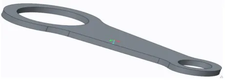
Three different models are showing in the form of figures.
[image:1.595.319.550.669.753.2]© 2018, IRJET | Impact Factor value: 6.171 | ISO 9001:2008 Certified Journal | Page 17 Fig 2: Vertical cut through center section
Fig 3: Horizontal cut through center section
Figure 1 shows the basic model of connecting rod, moreover other two designs shows modified version. Figure 2 illustrates that optimization of connecting rod has been done by vertical cut whereas in figure 3 it has been done by horizontal cut.
The modelled design of Creo2.0 is imported on Hypermesh13.0 in the solver Optistruct and it is subjected to the boundary condition. Designed models are divided into the meshing. Tetramesh and Tria mesh is used for solid, horizontal and vertical cut connecting rod. The element size is supposed to be 2.00 in all cases.
[image:2.595.39.287.80.262.2]Now three material AISI4340, Aluminium 7068[5] and Aluminium boron carbide[6]. The mechanical properties of the material is given below table 1.
Table 1: Mechanical Properties of material
Name
/Properties Young Modulus (GPa) Density (Kg/m3) Poisson’s ratio
AISI4340 200 7.850 0.280
Al 7068 73.1 2.850 0.330
Al4BR 362 2.300 0.180
Table 2 describes the weight of all connecting rod along with selection of material. Overall volume of solid, vertical cut and horizontal cut are 30759, 21807.9, 22081.3 mm3
respectively.
Table 2:Mass Calculation of designs
Name\Material AISI 4340 Al 7068 Al4BC
Solid 242gm 88 gm 70.5 gm
Vertical Cut 173 gm 63 gm 50.8 gm
Horizontal Cut 171 gm 62 gm 50.2 gm
This calculation reveals the weight reduction make the component cost effective. After analysing the calculations the most optimum component is vertical cut connecting rod of Al7068. The percentage change is near around 74% as compare to solid connecting rod of AISI4340.
3. LOADING CONDITION
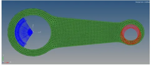
All the connecting rod include solid vertical and horizontal are subjected into the various tensile stress. The smaller end is consider fix by the application of constraints. The bigger end is set at the loading condition of pressure from 10Mpa to 50Mpa.It is shown in figure 4.
Fig 4: Model after loading condition
The section is consider at both the end by trimming the surface, so that the von misses stress is calculated accurately. Now create the load step by which fix and loads are define into the HYPERWORKS.
Fig 5
Figure 5 shows the von misses stresses of solid connecting rod whose material is AISI4340. Maximum von misses stress develop in a connecting rod at 50Mpa is
261.5N/mm2. While minimum von misses stress develop
in a connecting rod at 10 Mpa is 52.29 N/mm2.
[image:2.595.312.555.239.344.2] [image:2.595.310.560.437.548.2] [image:2.595.40.282.536.608.2]© 2018, IRJET | Impact Factor value: 6.171 | ISO 9001:2008 Certified Journal | Page 18 Figure 6 shows the von misses stresses of solid connecting
rod whose material is Al7068. Maximum von misses stress develop in a connecting rod at 50Mpa is 257.0N/mm2. While minimum von misses stress develop in a connecting rod at 10 Mpa is 51.39N/mm2
Fig 7
Figure 7 describes the von misses stresses of solid connecting rod whose material is Al4BC. Maximum von misses stress develop in a connecting rod at 50Mpa is
267.6.0N/mm2. Whereas minimum von misses stress
develop in a connecting rod at 10 Mpa 53.5 N/mm2.
Chart 1
Chart 1 illustrates that comparison of all material on solid connecting rod. In which this chart shows that, any of this material can be used at 10 Mpa to 50 Mpa because the change in von misses stress is in under 4% . After the analysis of material Al 7038 shows minimum stress at 50 Mpa.
Fig 8
Figure 8 shows the von misses stresses of vertical cut connecting rod whose material is AISI4340. Maximum Von misses stress develop in a connecting rod at 50 Mpa is
284.2 N/mm2. On the other hand minimum von misses
stress develop in a connecting rod at 10 Mpa is 56.8N/mm2.
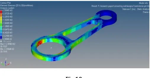
[image:3.595.42.281.143.260.2]Fig 9
Figure 9, the von misses stresses of vertical cut connecting rod whose material is Al 7068. Maximum von misses stress develop in a connecting rod at 50Mpa is
280.4N/mm2. While minimum von misses develop in a
connecting rod at 10 Mpa is 56.08 N/mm2.
Fig 10
Figure 10, the von misses stresses of vertical cut connecting rod whose material is Al4BC. Maximum von misses stress develop in a connecting rod at 50Mpa is
289.4N/mm2. While minimum von misses stress develop
in a connecting rod at 10 Mpa is 57.84 N/mm2.
Chart 2
10 Mpa
20 Mpa
30 Mpa
40 Mpa
50 Mpa AISI 4340 52.29 104.6 156.9 209.2 261.5
Al 7038 51.39 102.8 154.2 205.6 257
Al4BC 53.5 107 160.6 214.1 267.6
0 50 100 150 200 250 300
V
on
m
isses
st
re
ss
10 Mpa
20 Mpa
30 Mpa
40 Mpa
50 Mpa
AISI 4340 56.8 113.7 170.5 227.4 284.2
Al 7068 56.08 112.2 168.3 224.3 280.4
Al4BC 57.87 115.7 173.6 231.5 289.4
0 50 100 150 200 250 300 350
V
on
m
isses
St
re
[image:3.595.308.570.157.269.2] [image:3.595.309.563.371.503.2]© 2018, IRJET | Impact Factor value: 6.171 | ISO 9001:2008 Certified Journal | Page 19 Chart 2 describes comparison of all material on vertical
[image:4.595.310.561.66.227.2]cut connecting rod. In which this chart shows that, any of this material can be used at 10 Mpa to 50 Mpa because the change in von misses stress is in under 4%. After the analysis of materials Al 7068 shows minimum stress at 50 Mpa.
Fig 11
Figure 11, the von misses stresses of horizontal cut connecting rod whose material is AISI4340. Maximum von misses stress develop in a connecting rod at 50Mpa is
303.3N/mm2. While minimum von misses stress develop
in a connecting rod at 10 Mpa is 60.67 N/mm2.
Fig 12
Figure 12, the von misses stresses of horizontal cut connecting rod whose material is Al 7068. Maximum von misses stress develop in a connecting rod at 50Mpa is
300.6N/mm2. While minimum von misses stress develop
[image:4.595.36.290.154.279.2]in a connecting rod at 10 Mpa is 60.12 N/mm2.
Fig 13
Figure 13 ,the von misses stresses of horizontal cut connecting rod whose material is Al4BC. Maximum von misses stress develop in a connecting rod at 50Mpa is
307.3N/mm2. While minimum von misses stress develop
in a connecting rod at 10 Mpa is 61.46 N/mm2.
Chart 3
Chart 3 describes comparison of all material on horizontal cut connecting rod. In which this chart shows that, any of this material can be used at 10 Mpa to 50 Mpa because the change in Von misses stress is in under 4%. After the analysis of material Al 7068 shows minimum stress at 50 Mpa.
Chart 4
Chart 4 describes the comparison of material AISI4340 on solid, vertical, and horizontal cut connecting rod. In which the chart shows that, any of the designs can be used at 10 Mpa to 50 Mpa because the change in Von misses stress is in under 15%.
Chart 5
10 Mpa
20 Mpa
30 Mpa
40 Mpa
50 Mpa
AISI 4340 60.67 121.3 182 242.7 303.3
Al 7068 60.12 120.2 180.4 240.5 300.6
Al4BC 61.46 122.9 184.4 245.9 307.3
0 50 100 150 200 250 300 350
V
on
m
isses
S
tr
e
sses
10 Mpa
20 Mpa
30 Mpa
40 Mpa
50 Mpa
Full Solid 52.29 104.6 156.9 209.2 261.5
Verticle Cut 56.8 113.7 170.5 227.4 284.2 Horizontal
Cut 60.67 121.3 182 242.7 303.3
0 50 100 150 200 250 300 350
V
onm
isse
s
St
re
ss
10 Mp
a 20 Mp
a 30 Mp
a 40 Mp
a 50 Mp
a
Full Solid 51.39 102.8 154.2 205.6 257
Vertical Cut 56.08 112.2 168.3 224.3 280.4
Horizontal cut 60.12 120.2 180.4 240.5 300.6 0
50 100 150 200 250 300 350
V
onm
isse
ss
St
re
[image:4.595.316.567.344.514.2] [image:4.595.36.297.366.493.2] [image:4.595.35.296.581.691.2]© 2018, IRJET | Impact Factor value: 6.171 | ISO 9001:2008 Certified Journal | Page 20 Chart 5 describes the comparison of material Al7068 on
solid, vertical, and horizontal cut connecting rod. In which the chart shows that, any of the designs can be used at 10 Mpa to 50 Mpa because the change in Von misses stress is in under 15%.
Chart 6
Chart 6 describes the comparison of material Al4BC on solid, vertical, and horizontal cut connecting rod. In which the chart shows that, any of the designs can be used at 10 Mpa to 50 Mpa because the change in Von misses stress is in under 15%.
4. CONCLUSIONS
This is a general study on the designs along with the consideration of all aspects of industrial material uses in the connecting rod. The main objective of this paper is to optimize weight and make the component lighter with in a permissible limit. These are following results:
Weight is reduced upto 74% of solid connecting rod of AISI4340 to the vertical cut connecting rod of Al7068.
After the analysis of von mises stresses for 10 Mpa to 50 Mpa, the vertical cut connecting rod is used instead of solid connecting rod if permissible limit is consider upto 10%.
Further more, if permissible limit is considered upto 15% the horizontal cut centre section connecting rod of Al7068 can be used in the place of solid connecting rod of Al7068..
5. REFRENCE
[1] Christy V Vazhappilly, P.Sathiamurthi, “Stress Analysis of Connecting Rod for Weight Reduction- A Review” , International Journal of Scientific and Research Publications, Volume 3, Issue 2, February 2013, ISSN 2250-3153.
[2]Prof. N.P.Doshi, Prof. N.K.Ingole,” Analysis of Connecting Rod Using Analytical and Finite Element Method”, International Journal of Modern Engineering
Research (IJMER), Vol.3, Issue.1, Jan-Feb. 2013 pp-65-68, ISSN: 2249-6645.
[3] Mithilesh K Lade, Ritesh P Harode, Deepali Bankar Lade,” Static Load Analysis of Carbon Fiber Connecting Rod”, International Journal of Research in Advent Technology, Vol.3, No.9, September 2015 E-ISSN: 2321-9637.
[4] Prof. Vivek C. Pathade , Dr. Dilip S. Ingole, “Stress Analysis of I.C.Engine Connecting Rod by FEM and Photoelasticity”, IOSR Journal of Mechanical and Civil Engineering (IOSR-JMCE) e-ISSN: 2278-1684 Volume 6, Issue 1 (Mar. - Apr. 2013), PP 117-125.
[5] Tukaram S. Sarkate, Sachin P. Washimkar, Sachin S. Dhulekar, “Optimization of steel connecting rod by aluminum connecting rod using finite element analysis”, International Journal of Recent Advances in Engineering & Technology (IJRAET), ISSN (Online): 2347 - 2812, Volume-1, Issue - 1, October, 2013.
[6] K.Sudershn Kumar, Dr. K. Tirupathi Reddy, Syed Altaf Hussain,” Modeling and Analysis of Two Wheeler Connecting Rod”, International Journal of Modern Engineering Research (IJMER), Vol.2, Issue.5, Sep-Oct. 2012 pp-3367-3371.
[7] Chen, N., L. Han, W. Zhang and X. Hao, 2006. "Enhancing Mechanical Properties and Avoiding Cracks by Simulation of Quenching Connecting Rod". Material Letters, 61: 3021-3024.
[8] Shigley, J.E. and C.R. Mischke, 2001. "Mechanical Engineering Design", McGraw-Hill, New York, 776. Webster, W.D., R. Coffell and D. Alfaro, 1983.
[9] Cioata V G, kiss I. (2010) “Computer Aided Design of the Connecting Rod” F aculty o f Technic a l Sciences Novi Sad, Machine Design”.
[10] Teruie Takemasu, Victor Vazquez, Brett Painter and Taylan Altan, 1996 “Investigation of Metal Flow and Perform Optimization in Flash Less Forging of a Connecting Rod”, Journal of Materials Processing Technology, No. 59, 95-105
10 Mpa
20 Mpa
30 Mpa
40 Mpa
50 Mpa
Full Solid 53.5 107 160.6 214.1 267.6
Verticle Cut 57.87 115.7 173.6 231.5 289.4 Horizontal
Cut 61.46 122.9 184.4 245.9 307.3
0 50 100 150 200 250 300 350
V
on
m
isses
St
re