© 2017, IRJET | Impact Factor value: 5.181 | ISO 9001:2008 Certified Journal
| Page 1402
A Distributed Time Triggered Control for a Feedback Control System
Hoang Dung Bui
Faculty of International Training, Thai Nguyen University of Technology,
666, 3-2 stress, Thai Nguyen City, 251182, Vietnam
---***---Abstract -
The paper presents a distributed time triggeredcontrol using time triggered CAN (TTCAN) for a closed-loop control system. The balance of computing load is the rule to separate the control system into functional parts for controllers. The controllers are operated by time triggered control with TTCAN communication. The challenge is minimizing the response time to regulate the controlled system. It is done by adjusting the processing cycle that depends on the tasks’ processing time, data transmission time and the clock synchronizing drift. The system operation is managed by the communication and operation schedules which are also able to deal with several aperiodic events. The designs are experimented on an inverted rotary pendulum with the processing period of three milliseconds. The tasks and communication activities are triggered at the predefined time points and processed within the designed intervals. That makes the pendulum working stably at upright position. Key Words: distributed control, time triggered, feedback control system, Inverted rotary pendulum, TTCAN
1.
INTRODUCTION
Distributed control is applied for a distributed network system which consists of multiple subsystems [1]. The subsystems called nodes receive data and transmit the output via communication network to implement the tasks. To regulate a closed-loop control system, real time control is required. It means the tasks in the system must be completed before the deadlines [2].
Time triggered CAN has wide application in industrial application with advantages such as high dependability, deterministic communication and low latency jitters of transmitting messages [3-4]. In the protocol, all events such as transmitting or receiving in the system are activated by time segment elapsing [3]. Despite of drawbacks such as lack on flexibility and the restrictive design process, it is significantly suitable for a closed-loop control system that works autonomously and has little interaction with human [3].
In the paper, a distributed time triggered control is designed for an inverted rotary pendulum (IRP) using TTCAN as communication mean. The challenge is minimizing the response time to make the calculated value from the control program still valuable to regulate the IRP. To shorten the response time, there are two problems to solve. The first one is all critical tasks that directly affect to the control process such as data collection, data processing and actuator control
must be implemented inside predefined intervals. The second one is the communication has to perform deterministically with little latency. Moreover, the distributed control can handle the events such as adjusting the input from the operator, or displaying the IRP’s states. The distributed control is performed on a set of controllers which cannot individually process all the tasks. The tasks are assigned to controllers based on the balance of computation load. To manage the system operation, communication and operation schedules are built. And the controllers’ clocks are synchronized.
FreeRTOS is deployed for the controllers as operation system. It gives the priority for the task which should perform ahead if two tasks perform at the same time [5]. Therefore, ensuring the critical tasks are implemented at predefined time points.
The paper’s content is as follow: section 2 discusses about distributed control, section 3 mentions about Time Triggered Control. Section 4 describes the experiment and results, and the conclusion is discussed in section 5.
2. DISTRIBUTED CONTROL
To design a distributed control, the controlled system is analyzed the functionality then separated into tasks. Based on the rule of balance of computing load, the tasks are grouped and assigned to the controllers.
2.1 Inverted Rotary Pendulum
IRP is a two links system with two rotational joints as shown on Fig -1. It consists of an arm and a bar that rotate around the Z- and Y-axis with two angles α and , respectively. In steady state, mass M stands at the upright position and the arm stays at a desired position.
© 2017, IRJET | Impact Factor value: 5.181 | ISO 9001:2008 Certified Journal
| Page 1403
Fig -1: IRP’s structure
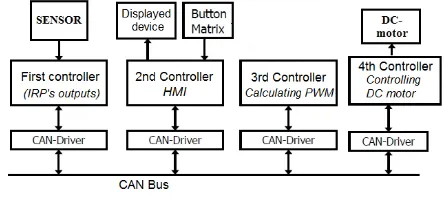
Based on the above analysis, the IRP control program consists of the main parts: Sensors signal collecting, data processing, DC – motor controlling, and Human – Machine Interface.
2.2 Distributed Control
From the previous analysis, the control program is separated into individual tasks, and the order of the data needed to control the IRP. The tasks are continued to analyze further following.
The first task is to handle the sensor’s signals. The sensors detect any change of the IRP’s outputs, and adjust the output variables. The variable’s values then are transmitted to other nodes at the time points which are predefined by the communication schedule. The task causes the hosted controller working under highly frequent interrupt due to the sensor’s signals.
The second task is to process the data including output variables and the reference input. To calculate the PWM values for the DC motor, the task contains many parameters such as control coefficients, IRP’s parameters and states [6]. Therefore, it has high computing load in the IRP control program and is dedicated a controller to perform.
The third task is to control the DC motor. Similarity to the first task, the controller which hosts the task implements other tasks under highly frequent interrupt. All three tasks above are required hard real-time performance [2] to keep the IRP operating stable.
Another function of the IRP is to create a human – machine interface. It contains two parts: one is for displaying the IRP’s states on a display device, and another one is for handling the operator command via an input device such as a push bottom matrix. The latter task deals with emergency situation or adjusting the input, thus it is required hard real-time control. There is no consequence if violating the deadline, thus the former task classified as soft real-time control [2].
The order of tasks’ implementation is: the first task receives the sensors’ signals, update the values to the output
variables then send the values to other controllers. The second task gets the data from the first task to calculate the PWM value. The third one then uses the PWM value to export corresponding energy level to the DC motor. From the analysis, the distributed control for the IRP is designed with four controllers and shown on the Fig -2. The second task has highest computing load, thus is assigned to one controller – the third one. The first and the third tasks have a common feature that is invoked with high frequency. Therefore, both are assigned for the first and four controllers, respectively. The HMI function is in charge of the second controllers.
Fig -2: Distributed Control
The messages are exchanged in the network by TTCAN communication which is discussed in the next section.
3. TIME TRIGGERED CONTROL
Deploying the distributed control, two kinds of schedules are set up to manage the communication and operation of the controllers. The first one called Communication Schedule is used to manage TTCAN communication. The second one is Operation Schedule, which controls the controllers’ operation.
3.1 Time Triggered CAN
In the protocol, communication activities are triggered by the time elapsing and happened periodically. The period is called basic cycle, which consist of multiple time slots [3]. Each time slot is started by a Time Mark. The communication schedule is designed to activate a particular event at the right Time Mark and point out the related controllers. Time slot interval is then analyzed following.
Communication Schedule
[image:2.595.40.243.93.276.2] [image:2.595.320.544.253.353.2]© 2017, IRJET | Impact Factor value: 5.181 | ISO 9001:2008 Certified Journal
| Page 1404
Master. Therefore, there are four message frames which are corresponding to four time slots. One more time slot is for redundancy and another one is to distinguish two consecutive basic cycles. All the time slots and the activities in four nodes are shown on Fig -3.
At Time Mark ‘0’, the starting point of a basic cycle, TimMas frame is sent from Time Master, which manages the global time of the system. After receiving, all the non-master nodes use the frame’s data to synchronize the global time [3].
Fig -3: Communication Schedule
In the same time slot, Sensor frame which stores the current IRP’s outputs is prepared to transmit. In time slot ‘1’, it is sent to other controllers. The frame’s data is shown on the display device, update working ranges of the pendulum, and used to calculate the PWM value. As the calculation is done, its result is transmitted via PWM frame in time slot ‘3’. The fourth controller uses this data to export amount of energy to regulate the motor. If any operator’s command is detected, it is sent to the third and fourth controller via Command frame in time slots ‘2’. It will stop the motor immediately if any incident occurs. The time slots ‘4’ is redundancy for emergency situation and future use.
Time Slot Interval TI
Due to the data order of controlling the IRP, the time slot interval is required long enough for both frame transmission and tasks’ processing. Therefore, two cases are considered to calculate the interval. The longer one will be used to set up the time slot interval. Moreover, the clock synchronizing time drifts Td and redundancy time for retransmission are also taken into account.
Case 1: Based on Transmission Time
The interval is required to complete a transmission of the longest frame. Due to the only difference in the data field, Sensor frame is the longest frame with six bytes with the transmitted time called TS. Combining with the retransmission redundancy time (equal to Ts) and the time drift of synchronizing the clocks Tc, the minimum time slot interval TI is:
TI = 2TS + Tc (1)
Case 2: Based on Processing Time
The processing time is considered for PWM_Calculation task which has highest computing load. The task is performed in the third controller - Time Master, thus there is no time drift. Therefore, the time slot interval is greater than processing time Tp:
TI ≥ TP (2) Based on the set up of CAN bus and the computing power of the controllers, TI calculated in the equation (1) and (2) will be different. The greater one is chosen for the time slot interval.
3.2. Controller Operation Schedules
This section describes how to organize the tasks in the controllers to meet two requirements: the critical tasks with hard real-time operation must be completed before the deadline and they must be synchronized with Communication Schedule. The synchronization is managed by the task Operation Schedule which is invoked at each Time Mark; then it triggers other tasks to work. The activated method is to send a signal to predefined queues that in turn waking up the specified tasks [4]. Due to the role, Operation Schedule has highest priority in the controllers.
[image:3.595.38.287.215.364.2]To analyze the controllers, Table -1 presents symbols and the meaning used to describe tasks’ structure.
Table -1: Symbol used for tasks’ structure description
Symbol Description
Message frame
Queue or semaphore Variable in controller
Task (|priority| task name|) or Interrupt Service Routine (ISR)
First Controller
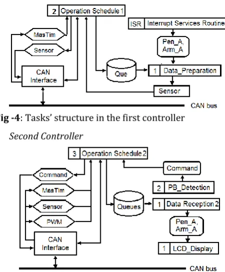
There are two tasks: Operation Schedule 1 and Data_Preparation. The data called variables are the IRP’s outputs – two angles Pen_A and Arm_A. They are updated by Interupt Service Routines (ISR) which detect the signals’ change from the encoders. At time mark ‘0’, Operation Schedule 1 sends a signal to the queue Que to invoke the task Data_Prepration whose duties is toprepares the data for Sensor frame. The frame is transmitted in time slot 1. In the time slot ‘0’, the controller receives MasTim frame from Time Master to synchronize the clock. The task’s structure is shown in Fig -4.
Angle
Pen_Angle
[image:3.595.324.538.460.551.2]© 2017, IRJET | Impact Factor value: 5.181 | ISO 9001:2008 Certified Journal
| Page 1405
Fig -4: Tasks’ structure in the first controller Second Controller
Fig -5: Task’s structure in the second controller
Due to managing the Human – Machine Interface, the controller is connected with two peripheral devices: a LCD and Pushing Button Matrix. To display IRP’s states, it needs two tasks: Data Reception 2 and LCD Display. The former one is waken up at time mark 1, 2, and 4 by Operation Schedule 2 to handles all the incoming frames (MasTim, Sensor, PWM). The frames’ data is then updated for the displayed variables. The latter one manages the LCD and shows the information of the screen. The third task PB_Detection is used to sense the Button Matrix, recognize the operator’s command, and pack it into a Command frame. The frame is transmitted to the destination at time mark ‘2’. The task’s composition is shown in Fig -5.
Third Controller
Fig -6: Task’s structure in the third controller
It is Time Master and used to calculate PMW value. As Command and Sensor frames have arrived, PWM_Calculation is waken up by Operation Schedule 3 to process the data. The result is packed in PWM frame and sent to the fourth
controller. Operation Schedule 3 task sends MasTim frame at time slot ‘0’.
Fourth Controller
The controller’s duty is to control amount of engery and rotated direction for the DC-motor. In order to control two working phases of the IRP, there are three tasks (Data Reception, Upright Controller, SwingUp Controller) cooperating shown on Fig -7.
Fig -7: Task’s structure of the fourth controller
As message frames come, Operation Schedule 4 sends a signal to Queue1 to wake up task Data Reception 4. Based on the received data (PWM, Sensor, Command), it processes and sends another signal to Queue2 or Queue3 to activate Upright_Controller task or SwingUp_Controller task, respectively. The tasks then affect to Interrupt Service Routine to control the energy level.
The distributed time triggered control is then applied to an IRP model. The experiement is implemented to determine the appropriate control parameters.
4. EXPERIMENT AND RESULTS
The design is applied on a IRP model, which was made in the university’s workshop. In the experiment, the signals of CAN bus and the states of the critical tasks are measured by MSO7014B Mixed Signal Oscilloscope. The results are discussed afterward.
4.1 Experiment
The IRP model is shown on Fig -8 which is driven by a DC motor 12V. The dynamic energy is transmitted via a gearbox, a belt transmission with the transmitted ratios 18 and 4, respectively. The revolution of the encoders’ is 2000 values/rev. The pendulum has mass 0.03 kg. The arm and pendulum’s bar have the lengths 0.13m and 0.4m. And the inertia moment of the base on which the arm is fixed is 0.002 Kgm2.
[image:4.595.41.266.97.369.2] [image:4.595.316.548.213.344.2] [image:4.595.39.268.551.690.2]© 2017, IRJET | Impact Factor value: 5.181 | ISO 9001:2008 Certified Journal
| Page 1406
microcontrollers (C) AT90CAN128. The CAN controllers on the Cs interact with physical bus via device PCA82C250. The C throughput achieves 16 MIPS at 16MHz, and the transfer rate of CAN bus is selected at 500kbits/s. By experiment, task PWM_Calculation consumes approximately 180 s to process, the transmission time of Sensor frame is approximate 230 s and the time drift of clock synchronization is 70 s. Applying formulas (1) and (2), the time slot interval is determined by 500 s (0.5 ms).
Fig -8: IRP model
The operation system in the Cs is FreeRTOS which is written by Embedded C [5]. It provides the functions to manage the task’s implementation and ensure the higher priority task will preemptive the lower one.
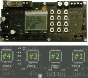
Fig -9: The Control Circuit Board (two sides)
4.2 Results and Discussion
As the IRP model operates at the steady state, the states of TTCAN communication and the hard real-time tasks are measured and shown on Fig -10 and -11. The units of the horizontal and vertical axes are 0.5 milliseconds and 5 voltages, respectively. As the communication channel or tasks are active, the captured signals are non-zero. Because of the repetition of activities, the analysis is carried out in a basic cycle.
On Fig -10, the yellow, green and purple signals represent the states of CAN bus, PWM_Calculation task, and the code for preparing data of reference frame (on the third controller), respectively.
[image:5.595.308.560.163.333.2]The first signal (the yellow one) is CAN bus signal showing the transmission of four message frames in time slot ‘0’, ‘1’, ‘2’, ‘3’ in a basic cycle. The transmission happens as the communication schedule with four message frames in chronological order: MasTim, Sensor, Command, and PWM.
Fig -10: CAN bus signal, states of task PWM_Calculation and Part of Operation Schedule
The data for MasTim frame is prepared by a piece of programing codes in Operation Schedule task. The state of the codes is captured and shown by the purple signal. It is active periodically at Time Mark ‘0’. The frame is only sent as its data is ready.
The green signal presents the state of PWM_Calculation task that is active in time slot ‘2’ after receiving Sensor frame. After completing the calculation, PWM value is packed in PWM frame which is sent on time slot ‘3’. The frame transmission is shown on CAN bus signal.
On CAN bus signal, there are time drift in transmitting two frames Sensor and Command. The sending points are later than the predefined Time Marks. Due to the delay of clock synchronization, the starting points of basic cycles of Time Master (the third controller) and other Cs are different. Time Master is not affected by this phenomenon. Its tasks and frames’ transmission are activated at the right Time Mark.
[image:5.595.73.248.214.345.2] [image:5.595.88.237.414.546.2]© 2017, IRJET | Impact Factor value: 5.181 | ISO 9001:2008 Certified Journal
| Page 1407
Fig -11: CAN bus signal, states of two tasks Data_Preparation and Upright_Controller
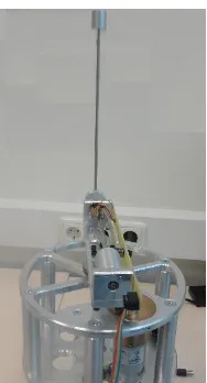
[image:6.595.115.209.415.589.2]From the figure, the two tasks are woken at middle of the time slot, not at the Time Mark. It is due to the time drift of clock synchronization between Time Master and other uCs. From the figures above, the critical tasks’ operation satisfies the hard real time requirement. They operate synchronously, are active and completed inside the predefined time slots. Fig -12 shows the IRP’s operation at steady state. The pendulum can be hold at upright position as long as it is connected to an electrical source.
Fig -12: IRP at steady state
5. CONCLUSIONS
The paper presents a distributed time triggered control for a closed-loop control system. The distributed control meets the real-time requirements and simplifies the structure of the IRP control program. It also can handle both the periodic and aperiodic events deterministically with little latency jitter. A simple method is used to calculate the time slot interval to minimize the basic cycle, thus reduce the effect of the response delay and time drift.
The presented control is deployed for a simple feedback control system with limited environment interaction. The response time to aperiodic events depends on basic cycle. In this experiment, the basic cycle of three milliseconds is able to handle well the operator commands such as stop immediately or adjusting reference input.
.
ACKNOWLEDGEMENT
I would like to give my gratitude to Dr. Walter Lang because of his support of FreeRTOS and TTCAN. His advices on designing and manufacturing the IRP model also gave me huge benefit in cost and time.
REFERENCES
[1] Albert, A. (2004) – Comparison of Event-Triggered and Time-Triggered Concepts with Regards to Distributed System, Embbeded World 2004, Nuernberg, Germany, page 235 - 252
[2] Kopetz, H. (2011) - Real time systems: Design Priciples for Distributed Embedded Applications, ISBN-13: 978-1461428664, New York: Springer.
[3] Kammerer, R. (2012). - TTCAN. In R. Obermaisser (Ed.), Time Trigger Communication, (pp. 221-244). ISBN: 978-1-4398-4661-2, Florida: CRC Press, Taylor & Francis Group
[4] Obermaisser, R. (2010) Event-triggerred and time-triggered control paradigms. ISBN-13: 978-1441935694, New York: Springer.
[5] Barry, R. (2014) - freertos.org/RTOS.html , Engineers Real Time Ltd