© 2017, IRJET | Impact Factor value: 6.171 | ISO 9001:2008 Certified Journal
| Page 1513
Design of Millimeter Wave Microstrip Patch Antenna For MIMO
Communication
Sridevi.S
1, Mr. K.Mahendran
21
Me applied electronics(ECE),
2Assistant professor(ECE)
1,2
Ck college of engineering and technology, Cuddalore
---***---Abstract -
In today world more than five billion wirelessdevices are currently being in use for voice and data transmission. The amount of mobile data usage has increased drastically. Here comes the MIMO technology with greater attention , in offering high data rate and spectral efficiency. The efficient deployment of MIMO requires efficient compact antenna. Design of compact microstrip patch antenna for MIMO system using HFSS software is proposed. The proposed antenna operates in mm wave frequency band that provides enhanced bandwidth and data rate.
Key Words: MIMO (multiple input multiple
output),HFSS(high frequency structure simulator),mm wave frequency
1. INTRODUCTION
With the explosive growth of mobile data demand, the fifth generation (5G) mobile network would exploit the enormous amount of spectrum in the millimeter wave (mmWave) bands to greatly increase communication capacity. There are fundamental differences between mmWave communications and existing other communication systems, in terms of high propagation loss, directivity, and sensitivity to blockage. These characteristics of mmWave communications pose several challenges to fully exploit the potential of mmWave communications, including integrated circuits and system design, interference management, spatial reuse, anti-blockage, and dynamics control. To address these challenges, we carry out a survey of existing solutions and standards, and propose design guidelines in architectures and protocols for mmWave communications. We also discuss the potential applications of mmWave communications in the 5G network, including the small cell access, the cellular access, and the wireless backhaul. Finally, we discuss relevant open research issues including the new physical layer technology, software defined network architecture, measurements of network state information, efficient control mechanisms, and heterogeneous networking, which should be further investigated to facilitate the deployment of mmWave communication systems in the future 5G networks.
2. PROPOSED SYSTEM
In the proposed system microstrip patch antenna is used with the Metamaterial substrate to improve the data rate and bandwidth at the mm frequency of 29.5 GHz so thereby
the data rate is increased up to 1Gbps.
.
3. DESIGN SPECIFICATION
It describes the specification of the design used for the deigning of microstrip patch antenna for MIMO communication.
3.1. MICROSTRIP PATCH ANTENNA
Probably the most popular and commonly used antenna type of the current decade is the microstrip patch antenna. The popularity of the microstrip patch antennas may have been fuelled by the development of the low cost manufacturing techniques of microstrip antennas. The popularity may also be attributed to the availability of the standard quality substrates for the manufacture of high frequency antennas. This may be evident from the fact that even though microstrip patch antennas were first reported in the decade of 1950 it took about two decades to attract researchers to this field. Also, the development of a particular technology is basically need oriented. As it is said “necessity is the mother of invention” the need for special type of antenna for communication to be used within missile systems and in handheld communication devices have found the solution with microstrip antennas.
© 2017, IRJET | Impact Factor value: 6.171 | ISO 9001:2008 Certified Journal
| Page 1514
developments, the size of the mobile communication deviceshave changed drastically. Microstrip patch antennas are low cost, low profile, light weight, high frequency planar antenna. It is a derivative of microstrip circuits.
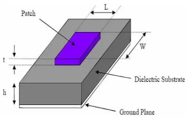
3.2. STRUCTURE OF MICROSTRIP PATCH ANTENNA
Microstrip antennas are three layered structures. The basic structure of microstrip antenna is shown in the figure . The top and the bottom layer consist of conducting surface of metal known as patch layer and ground layer respectively. The middle layer consists of non-conducting dielectric material known as dielectric layer. The dielectric constant (also termed as relative permittivity) εr of the dielectric material should be less than 10. Generally, t <<<λο, where, t is the thickness of the metal layers and λο is the free space resonant wavelength of the microstrip antenna.
Fig -1: microstrip patch antenna
3.3. PARAMETERS OF MICROSTRIP PATCH
ANTENNA
3.3.1. DIMENSIONS
The resonant length (the x axis in Figure 2) determines the resonant frequency and is about λd/2 for a rectangular patch excited in its fundamental mode where λd is the wavelength in the PCB material. The patch is actually a bit larger electrically than its physical dimensions due to the fringing fields and the difference between electrical and physical size is mainly dependent on the PC board thickness and dielectric constant of the substrate.
A good approximation for the resonant length is: L ≈ 0.49 λd = 0.49
This formula includes a first order correction for the edge extension due to the fringing fields, with:
• L = resonant length
• λd = wavelength in PC board • λ0 = wavelength in free space
εr = dielectric constant of the printed circuit board material
Other parameters that have less influence on the resonant frequency include:
•Ground plane size
•Metal (copper) and dielectric thickness •Patch (impedance) width
•Impedance Matching
3.3.2. RADIATION PATTERN
A patch antenna radiates power in certain directions and we say that the antenna has directivity (usually expressed in dBi). If the antenna had a 100% radiation efficiency, all directivity would be converted to gain. Typical half wave patches have efficiencies well above 90%. The directivity of a patch can be estimated quite easily: The radiating edges of a patch can be seen as two radiating slots placed above a ground plane and, assuming all radiation occurs in one half of the hemisphere (on the patch side of the ground), we get a 3 dB directivity increase. This would be an antenna with a perfect front-to-back ratio where all radiation occurs towards the front and no radiation towards the back.
3.3.3. BANDWIDTH
Another important parameter of an antenna is the bandwidth it covers. Most of the time only impedance or return loss bandwidth is specified. However, it is important to realize that several other definitions of bandwidth exist: directivity bandwidth, polarization bandwidth and efficiency bandwidth. Directivity and efficiency are often combined to gain bandwidth.
3.4. FEEDING TECHNIQUE
Microstrip line feed is one of the easier methods to fabricate as it is a just conducting strip connecting to the patch and therefore can be consider as extension of patch. It is simple to model and easy to match by controlling the inset position. However the disadvantage of this method is that as substrate thickness increases, surface wave and spurious feed radiation increases which limit the bandwidth.
[image:2.595.85.276.312.443.2] [image:2.595.344.561.627.722.2]© 2017, IRJET | Impact Factor value: 6.171 | ISO 9001:2008 Certified Journal
| Page 1515
3.5. mm WAVE FREQUENCY
The millimeter-wave region of the electromagnetic spectrum is usually considered to be the range of wavelengths from 10 millimeters (0.4 inches) to 1 millimeter (0.04 inches). This means millimeter waves are longer than infrared waves or x-rays, for example, but shorter than radio waves or microwaves. The millimeter-wave region of the electromagnetic spectrum corresponds to radio band frequencies of 20 GHz to 300 GHz and is sometimes called the Extremely High Frequency (EHF) range. The high frequency of millimeters waves as well as their propagation characteristics (that is, the ways they change or interact with the atmosphere as they travel) make them useful for a variety of applications including transmitting large amounts of computer data, cellular communications, and radar.
One of the greatest and most important uses of millimeter waves is in transmitting large amounts of data. Every kind of wireless communication, such as the radio, cell phone, or satellite, uses specific range of wavelengths or frequencies. Each application provider (such as a local television or radio broadcaster) has a unique “channel” assignment, so that they can all communicate at the same time without interfering with each other. These channels have “bandwidths” (also measured in either wavelength or frequency) that must be large enough to pass the information from the broadcaster’s transmitter to the user.
3.6. MIMO COMMUNICATION
Multi-user MIMO (MU-MIMO) is a set of multiple-input and multiple-output technologies for wireless communication, in which a set of users or wireless terminals, each with one or more antennas, communicate with each other. In contrast, single-user MIMO considers a single antenna transmitter communicating with a single multi-antenna receiver. In a similar way that OFDMA adds multiple access (multi-user) capabilities to OFDM, MU-MIMO adds multiple access (multi-user) capabilities to MIMO. MU-MIMO has been investigated since the beginning of research into multi-antenna communication, including work by Telatar on the capacity of the MU-MIMO uplink.SDMA, massive MIMO, coordinated multipoint (CoMP) and ad hoc MIMO are all related to MU-MIMO; each of those technologies often leverage spatial degrees of freedom to separate users.Multi-user MIMO (MU-MIMO) can leverage multiple users as spatially distributed transmission resources, at the cost of somewhat more expensive signal processing.
In comparison, conventional, or single-user MIMO considers only local device multiple antenna dimensions. Multi-user MIMO algorithms are developed to enhance MIMO systems when the number of users or connections is greater than one. Multi-user MIMO can be generalized into
two categories: MIMO broadcast channels (MIMO BC) and MIMO multiple access channels (MIMO MAC) for downlink and uplink situations, respectively. Single-user MIMO can be represented as point-to-point, pairwise MIMO.
Fig -3: MIMO communication
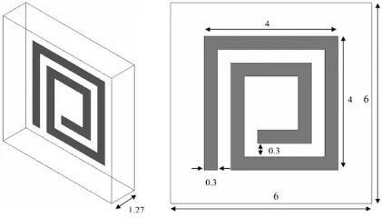
3.7. METAMETERIAL SUBSTRATE
Inside a dielectric material, the free space wavelength of an antenna is scaled down by a factor of , where is the relative electric permittivity and is the relative magnetic permeability of the material. Thus, the size of an antenna can be significantly reduced by choosing a high or high material. Though miniaturization can be achieved using high materials, it comes at the cost of increased dielectric losses that can significantly affect antenna efficiency. On the other hand, materials that exhibit a high in the microwave region do not exist in nature and designers have been compelled to use lossy high materials when antenna miniaturization is a key design requirement.
Fig -4: Metameterial substrate
[image:3.595.348.557.158.271.2] [image:3.595.329.539.484.604.2]© 2017, IRJET | Impact Factor value: 6.171 | ISO 9001:2008 Certified Journal
| Page 1516
4. SYSTEM DESIGN
The radiation or antenna pattern describes the relative strength of the radiated field in various directions from the antenna, at a constant distance.
C 1 fc= --- = ---
2L√ εr 2L√ε0εrµ0
1 L= ---
2fc√ε0εrµ0
The radiation pattern is a reception pattern as well, since it also describes the receiving properties of the antenna. The radiation pattern is three-dimensional, but usually the measured radiation patterns are a two dimensional slice of the three-dimensional pattern, in the horizontal or vertical planes.
The rectangular shaped microstrip patch antenna is designed of the desired meta material substrate dielectric substrate and the operating frequency of 29.5 GHz.
Dielectric constant=2.2 Dielectric height=1.6mm Operating frequency=29.5 GHz
Width=4.371mm Length=2.541mm
The proposed rectangular microstrip patch antenna is designed according to the above width and length.
5. SOFTWARE SPECIFICATION
5.1 HFSS SOFTWARE
HFSS is a commercial finite element method solver for electromagnetic structures from Ansys. The acronym stands for High Frequency Structure Simulator. It is one of several commercial tools used for antenna design, and the design of complex RF electronic circuit elements including filters, transmission lines, and packaging. It was originally developed by Professor Zoltan Cendes and his students at Carnegie Mellon University. Prof. Cendes and his brother Nicholas Csendes founded Ansoft and sold HFSS packaging. It was originally developed by Professor Zoltan Cendes and his
students at Carnegie Mellon University. Prof. Cendes and his brother Nicholas Csendes founded Ansoft and sold HFSS stand-alone under a 1989 marketing relationship with Hewlett-Packard, and bundled into Ansoft products.In 1997 Hewlett-Packard acquired Optimization Systems Associates Inc. (OSA), a company John Bandler founded in 1983. HP's acquisition was driven by the HP's need for an optimization capability for HFSS.After various business relationships over the period 1996-2006, HP (which became Agilent Esof EDA division) and Ansoft went their separate ways,Agilent with the critically acclaimed FEM Element and Ansoft with their HFSS products, respectively. Ansoft was later acquired by Ansys. HFSS is high frequency structure simulator it is high performance full wave electromagnetic field simulator 3D volumetric passive device modelling that takes advantages of familiar Microsoft Windows graphical user interface .
It integrates simulation, visualization ,solid modelling and automaton in easy to learn. ANSOFT HFSS is an industry standard simulation tool for 3D full wave electromagnetic field simulation. The acronym HFSS originally stood for high frequency structural simulator. It is commercial finite element method solver for electromagnetic structures from ANSYS Corporation.
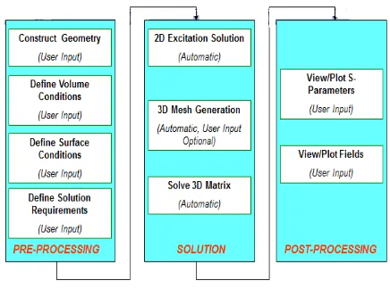
Fig -5: HFSS analysis design flow chart
HFSS delivers 3-D full-wave accuracy for components to enable RF and high-speed design. By leveraging advanced electromagnetic field simulators dynamically linked to powerful harmonic-balance and transient circuit simulation, HFSS breaks the cycle of repeated design iterations and lengthy physical prototyping.
6. REESULTS AND DISCUSSION
[image:4.595.328.546.391.553.2]© 2017, IRJET | Impact Factor value: 6.171 | ISO 9001:2008 Certified Journal
| Page 1517
Fig -6: Design By Using HFSS Software
The above diagram describes the design of the microstrip patch antenna and the length and width of the antenna is selected as per the calculation depends upon the frequency used, here the frequency used is the millimeter wave frequency.
Fig -7: Return loss
The above image represents the return loss characterists of the designed patch antenna.
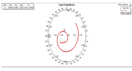
Fig -8: Input impedance
The above image represents the input impedance of the designed microstrip patch antenna
Fig -8: Gain of the Designed Antenna
The obtained radiation pattern of the rectangular shaped microstrip patch antenna, it shows the 3D view of the radiation pattern.
6. CONCLUSION
The rectangular shaped microstrip patch antenna is designed by using the metameterial as the substrate at the frequency range of 29.5ghz to increase the bandwidth and the data rate and the data rate is increased up the 1Gbps,so the number of users can be increased with high efficiency.
REFERENCES
[1] Sourav Nandi and Akhilesh Mohan, “ A Compact
Dual- Band MIMO Slot Antenna for WLAN Applications”,2017. IEEE Antennas and Wireless Propagation Letters
[2] Debdeep Sarkar and Kumar Vaibhav Srivastava, “A
Compact Four Element MIMO / Diversity Antenna
with Enhanced Bandwidth”, International
Conference on Signal Processing 2017
[3] Tursunjan Yasin and Reyhan Baktur, “ Bandwidth
Enhancement of Meshed Patch Antennas through Proximity Coupling”IEEE,2017.
[4] Behrouz Babakhani, and Satish K. Sharma, “ Dual
Null Steering and Limited Beam Peak Steering Using
Triple Mode Circular Microstrip Patch
Antenna”,IEEE Transactions on Antennas and Propagation ,2017
[5] Manidipa Roy and Ashok Mittal, Sr. Member,
“Recent Advancements in techniques to suppress surface wave propagation in Microstrip Patch Antenna”, IEEE International Conference on "Computational Intelligence and Communication Technology" (IEEE-CICT 2017)
[6] Ali Foudazi1 , Thomas E. Roth, Mohammad T. Ghasr,
[image:5.595.298.555.53.230.2] [image:5.595.35.283.60.224.2] [image:5.595.74.281.330.463.2] [image:5.595.70.295.525.647.2]© 2017, IRJET | Impact Factor value: 6.171 | ISO 9001:2008 Certified Journal
| Page 1518
antenna fed by orthogonal SIW line formillimetre-wave imaging applications” IET Micromillimetre-waves, Antennas & Propagation,2017 R. Kiruthika, Dr. T. Shanmuganantham, Rupak Kumar Gupta,
[7] “ A Fan Shaped Triple Band Microstrip Patch
Antenna with DGS for X-band
Applications”International Conference on Control,
Instrumentation, Communication and
Computational Technologies,2016.
[8] Chandiea, K.Anusudha“Pentagon Shaped Microstrip
Patch Antenna With Metamaterial For UWB Application”, 2016 International Conference on Control, Instrumentation, Communication and Computational Technologies 2016
[9] Rupak Kumar Gupta, Dr. T. Shanmuganantham, R.
Kiruthika, “A Staircase Hexagonal Shaped Microstrip Patch Antenna for Multiband Applications”International Conference on Control,
Instrumentation, Communication and
Computational Technologies,2016.
[10] Nagaraj Hanchinamani, Dr. C.R. Byrareddy,