Design Study of Environment Friendly Vapor
Absorption Refrigeration System of a Unit
Capacity using Li- Br and Water as Working Fluid
Sachin Kaushik
1, Dr. S. Singh
21 (M. Tech Scholar, Department of Mechanical Engineering) 2 (Associate Professor, Department of Mechanical Engineering)
BipinTripathiKumaon Institute of Technology, Dwarahat, Almora, Uttarakhand (India) 263653
Abstract ̶The objective of this paper is todesign and study an environment friendly vapour absorptionrefrigeration system of unit capacity using Li- Br and water as the working fluids.The thermodynamic design of L1 Br-water absorption refrigeration systems is usually based on assumed steady-state operating conditions. Absorber, condenser and evaporator temperatures are fixed as well as the temperature approach in the solution heat exchanger. System refrigerating capacity is also known 1.5 ton and then final design parameters are illustrated.
Keywords ̶Solar absorption refrigeration, Thermodynamic design, Low grade energy, Li-Br& Water.
I. INTRODUCTION
In recent developments of thermal engineering the Refrigeration technologies play an important role in today's industrial applications [1].
Design of refrigeration systems for cold storage to provide safety, economy, and reliability. Refrigeration design is a specialized field of thermal engineering. The design of cold storage refrigerated systems should be performed by an experienced refrigeration design engineer. A “plan and specify”
or a “design-build” arrangement can perform the refrigeration design. Design-build has been the trend of the refrigerationindustry. In many cases, equipment manufacturers have significantly supported the refrigeration design.
Design is considered to be the most important step in deciding the performance of a component. Any component before its fabrication has to be designed and actual working of a component depends upon how correctly and accurately the component has been designed.
In general design of a component involves determining important parameters likeheat transfer coefficients, heat transfer area, diameter of the, length etc. of the components. Design is themain part of this work so a detail design study of eachcomponent of the system has been done and explained in the next section [3].
exchanger provides fairly large ratios of heat transfer area to volume and weight. It provides this surfacein a form that is relatively easy to construct in a wide range of sizes and that is mechanicallyrugged enough to withstand normal shop fabrication stresses, external and internal stressesencountered under normal operating conditions, easy dismantling for cleaning and repairwork. Moreover the type of the tube and flow arrangement required for various processes likecondensation, absorption etc. taking place in the system does not permit the use Double Pipetype Heat Exchanger. Therefore it is better to design considering Shell and tube HeatExchanger[5].
Criteria For A Successful Heat Exchanger Design
It must be able to perform given heat duty and to retain the capability to do this in thepresence of fouling until the next scheduled maintenance period. The second criterion is thatthe heat exchanger must withstand the service conditions of the plant environment. Theimmediate consideration here is the mechanical stresses, there are external mechanicalstresses imposed by the piping on the exchanger by both steady state and transient flow andtemperature variations of the streams. The exchanger must resist corrosion by the service andprocess streams and by the environment. Third, the exchanger must be maintainable, whichusually means choosing a
configuration that permits cleaning as required and replacement oftubes, gaskets, and any other
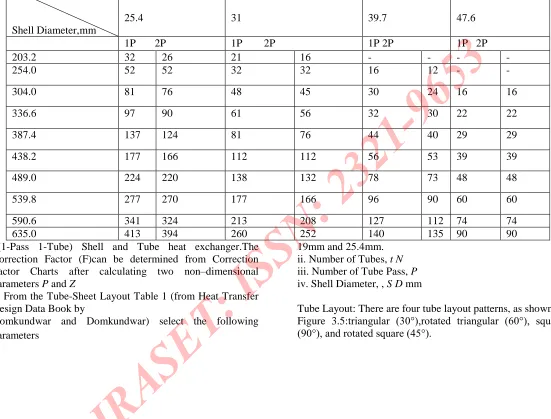
Table 1 :Tube sheet layout (number of tubes) (square pitch arrangement.
components that are especially vulnerable to corrosion, erosion,vibration, or aging. Fourthly, the exchanger should cost as little as possible, consistent with the above criteria being satisfied[6].
Basic Construction of a Shell and Tube Heat type Exchanger:
The main parts of a Shell and Tube Heat Exchanger are i) Shell
ii) Tubes iii) Baffles iv) Tube-sheet
General Design Procedure:
The design of a heat exchanger component generally involves finding the importantparameters like Heat transfer coefficients h, heat transfer Area, Length of tubes L,Number of tubes Nt.
Although there are small differences in design of above mentioned components, ageneral procedure for Design of Shell and tube Heat Exchanger can be stated as follows.
1. The characteristics of fluids contribute to a fundamental property of heat exchangers—
TheHeat Transfer rate (Q). The heat transferred to the colder fluid must equal that transferredfrom the hotter fluid, according to the following equation:
Q=mhot×Cp,hot×(Thot,in-Thot,out)=mcold×Cp,cold×(Tcold,out-Tcold,in) Q=UAF(LMTD)
The various symbols in these equations have their
usual meanings. The symbol 'F'stands for a Correction Factor that must be used with the log mean temperature difference fora counter- current heat exchanger to accommodate the fact that the flow of the two streamshere is more complicated than simple counter-current or co-current flow. The
LMTD wasdeveloped for a model restricted to parallel and counter-current flow patterns. In shell
This has been clearly illustrated in the figure below for
1-1(1-Pass 1-Tube) Shell and Tube heat exchanger.The Correction Factor (F)can be determined from Correction Factor Charts after calculating two non–dimensional parameters P and Z
2. From the Tube-Sheet Layout Table 1 (from Heat Transfer Design Data Book by
Domkundwar and Domkundwar) select the following parameters
i. Tube OD, mm. Two most commonly used tube OD are
19mm and 25.4mm. ii. Number of Tubes, t N iii. Number of Tube Pass, P iv. Shell Diameter, , S D mm
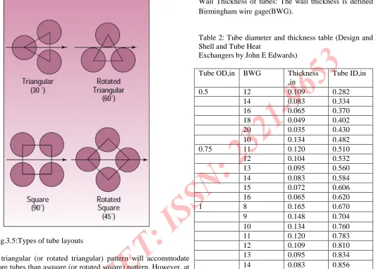
Tube Layout: There are four tube layout patterns, as shown in Figure 3.5:triangular (30°),rotated triangular (60°), square
(90°), and rotated square (45°).
TubeOD,mmPitchmm
Shell Diameter,mm
19
25.4
25.4
31
31
39.7
38.1
47.6
1P 2P 1P 2P 1P 2P 1P 2P
203.2 32 26 21 16 - - -
-254.0 52 52 32 32 16 12 -
-304.0 81 76 48 45 30 24 16 16
336.6 97 90 61 56 32 30 22 22
387.4 137 124 81 76 44 40 29 29
438.2 177 166 112 112 56 53 39 39
489.0 224 220 138 132 78 73 48 48
539.8 277 270 177 166 96 90 60 60
590.6 341 324 213 208 127 112 74 74
[image:4.612.28.579.149.568.2]Fig.3.5:Types of tube layouts
A triangular (or rotated triangular) pattern will accommodate more tubes than asquare (or rotated square) pattern. However, at the typical tube pitch of 1.25 times the tube
O.D, it does not permit mechanical cleaning of tubes, since access lanes are not available.
Consequently, a triangular layout is limited to clean shell-side services. For services that
require mechanical cleaning on the shell-side, square patterns must be used.
Pitch: Tube pitch is defined as the shortest distance between two adjacent tubes. TEMAspecifies a minimum tube pitch of 1.25 times the tube O.D. (Heat exchanger configurationsare defined by the numbers and letters established by the Tubular Exchanger Manufacturers
Association (TEMA)).
[image:5.612.31.564.120.501.2]Wall Thickness of tubes: The wall thickness is defined by the Birmingham wire gage(BWG).
Table 2: Tube diameter and thickness table (Design and Rating Shell and Tube Heat
Exchangers by John E Edwards)
Tube OD,in BWG Thickness ,in
Tube ID,in
0.5 12 0.109 0.282
14 0.083 0.334
16 0.065 0.370
18 0.049 0.402
20 0.035 0.430
10 0.134 0.482
0.75 11 0.120 0.510
12 0.104 0.532
13 0.095 0.560
14 0.083 0.584
15 0.072 0.606
16 0.065 0.620
1 8 0.165 0.670
9 0.148 0.704
10 0.134 0.760
11 0.120 0.783
12 0.109 0.810
13 0.095 0.834
14 0.083 0.856
3. Tube side Heat Transfer Coefficient, hi: It is simply the case of flow through cylindricaltubes. The tube side heat-transfer coefficient is a function of the Reynolds number, e R ,thePrandtl number, Pr .
These can be broken down into the following fundamental parameters:
physical properties (namely viscosity, thermal conductivity, and specific heat); tube diameter,
flow velocity. For turbulent flow through pipes (Re>2300) Nusselt Number
Nu =0.023 (Re)0.8(Pr)0.4
where Re i = Vdi / and pr= Cp/k
Nu = hi i d/ k= 3.66(For fully developed flow)
(Turbulent flow is usually preferred because it involves high heat transfer coefficients)[7].
4. Shell side Heat Transfer Coefficient, ho: The shell side calculations are far more complexthan those for the tube-side because of the involvement of various tube layout patterns, baffledesigns which together determine the shell side stream analysis. In a heat exchanger thatinvolves tube banks, the tubes areplaced in a shell and the fluid flows through the spacesbetween the tubes.
It is the case of flow across tube banks. Now the flow can be analyzed by twomethods. One method is given in book by Cengeland other given in the book by Holman.
We can use any of the method to calculate shell side heat transfer coefficient.
Heat Transfer Correlations given in the book by Cengel: The correlation given in book by Cengel is
Nu=hD/k =C ReD m
Prn(pr/prs) 0.25
(Zukauskas, 1987)
The value of C,mand n depends upon the value of Reynolds number.
Table 3 :Nusselt number correlations for cross flow over tube banks for number of rows
> 16 and 0.7 <Pr< 500 for In-line tube arrangement
Range of ReD Correlation
0-100 NuD=0.9ReD
0.4
Pr0.36(Pr/Prs) 0.25
100-1000 NuD=0.52ReD 0.5
Pr0.36(Pr/Prs) 0.25
1000-2×10⁵ NuD=0.27ReD 0.63
Pr0.36(Pr/Prs) 0.25 2×10⁵
-2×10⁶ NuD=0.27ReD 0.8
Pr0.4(Pr/Prs) 0.25
Here Reynolds number is defined on the basis of maximum velocity max V and notthe approach velocityV. This is because
Hence the Reynolds number is calculated on the basis of Vmaxas
Re= ( VmaxD)/
Now the Nusselt number in the table above is for 16 or more rows. For less number of rows .Nusselt number is to be multiplied by a Correction Factor F .
Table 4:Correction factor
N 1 2 3 4 5 7 10 13
In-line
0.70 0.80 0.86 0.90 0.93 0.96 0.98 0.99
N = Number of rows
Heat Transfer Correlations given in the book by Holman: The correlation given in
Holman’s book is
Nu=h0D0/K =CRenPr1/3
The Reynolds number, Re=( VmaxD0) / , where D0is the outside
diameter of a tube. Vmaxisthe “maximum” velocity of the fluid through the tube bank. To find it, first, the cross-flowarea must be evaluated. This is given as Cross flow area = Shell ID× Baffle spacing×Clearance /Pitch, where the clearance l and pitch n S (normal to the flow direction) are illustratedbelow for tubes in a square pitch.
Diagram showing tube clearance and Pitch
The clearance l=Sn-D0 When the volumetric flow rate of the
shell-side fluid is
divided by the cross-flow area defined here, it yields the
“maximum velocity” through thetube bank. All the properties
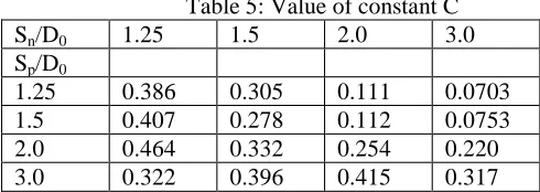
[image:6.612.306.551.567.654.2]should be evaluated at the arithmetic average temperature of thatfluid between the two end temperatures. The exponent n and the multiplicative constant Cdepend on the pitch to tube OD ratio, and are given in a table 5, table 6 provided in Holman’s book.
Sn/D0 1.25 1.5 2.0 3.0 Sp/D0
1.25 0.592 0.608 0.704 0.752 1.5 0.586 0.620 0.702 0.744 2.0 0.570 0.602 0.632 0.648 3.0 0.601 0.584 0.581 0.608
5. Calculation of Overall Heat transfer coefficient,U: When we have the value of hi andh0 we can calculate the overall heat transfer coefficient by the relation
= 1
+ × ln + ×
Fig 3.8 Diagram showing the thermal resistances
6. Calculation of LMTD
Fig.3.9 Temperature changes during (a) Counter Flow and (b) Parallel Flow
ln
∆Tm=LMTD=(Ө1-Ө2)/ln (Ө1/Ө2)
7. Calculation of Surface area required, A0=(Q/ U0F∆Tm)
8. Calculation of Length, L of the tubes by the relation,A0=Nt×π×d0×L
Design of Condenser: In the condenser the saturated water vapours coming from theGenerator are pass over cooling water pipes and are condensed to form saturated liquid water.The water vapors give up their heat of condensation and the cooling water takes away thisheat. The cooling water used is same that is coming from the Absorber outlet.Here saturated water vapours entering the condenser is the hot fluid and external incoming
cold water is the cold fluid.
Condensing temperature, Thi=Tho=300C
Cooling water inlet temperature,Tci=17.40C (outlet water temperature of Absorber)
Let cooling water outlet temperature,Tco=?
Choosing a heat exchanger with the following characteristics from the Tube Sheet Layout (Table 1)
Tube OD, d0=25.4mm
Taking BWG = 14,Thickness =2.11mm Tube ID, di=21.18mm
Number of Passes, P =2 Number of Tubes, Nt=16(4×4) Inner Shell Diameter, Ds=203.2mm
Pitch, Pt=1.25do =1.25×25.4 =31.75mm.
Final design results for Condenser 1. OD of tubes = 25.4mm
2. ID of Tubes = 21.18mm 3. Number of Tubes = 16 4. Number of Tube Pass = 2 5. Shell Diameter = 203.2mm
6. Heat transfer surface area = 0.644m2 7. Length of each tube per pass = 25.5cm
Design of Absorber
In the absorber, the water vapour produced by the evaporator is absorbed by aconcentrated strong lithium bromide solution falling in the form of fine droplets over cooledhorizontal tubes. The absorption of vapour in the liquid film is an exothermic process. Thecoolant water flowing through the tubes remove the excess heat produced due to absorption. Choosing a heat exchanger with the following characteristics from the Tube Sheet Layout
Table 1
Tube OD, do =25.4mm
Taking BWG = 10 ,Thickness =3.4mm Tube ID, di=18.6mm
Number of Passes, P =2 Number of Tubes, Nt=16(4×4)
Inner Shell Diameter, Ds=203.2mm
Pitch, P =1.25d0=1.25×25.4=31.75mm
Tube side heat transfer coefficient, i h :
Now, heat of absorption = heat taken by cooling water i.e. Q =m w×cpw×(Tco-Tci)
Let inlet temperature of cooling water =160C
Here two unknowns are present mwand Tco, one parameter has to be assumed.
Taking mw=1 kg / s
4. Number of Tube Pass = 2 5. Shell Diameter = 203.2mm
6. Heat transfer surface area = 2.81m2 7. Length of each tube per pass = 110cm
Design of Evaporator: In the evaporator saturated liquid water enters at the top of theshell and falls over chilled water pipes and boils into saturated water vapors' by taking heatof chilled water and hence producing refrigerating effect.Here saturated water entering the evaporator from the top is the cold fluid and water to becooled/chilled is the hot fluid.
Evaporator temperature, Te=4℃
Inlet temperature of chilled water, Tci=20℃
Outlet temperature of chilled water, Tco=?Tube OD, d0 =25.4mm
Taking BWG = 8 ,Thickness =4.19mm
Tube ID,di=17.02mm
Number of Passes, P=2
Number of Tubes, Nt=16 (4×4)
Inner Shell Diameter, DS=203.2mm
Pitch,P=1.25d0 =1.25×25.4=31.75 mm
Final design results for Evaporator 1. OD of tubes = 25.4mm
2. ID of Tubes = 17.02mm 3. Number of Tubes = 16 4. Number of Tube Pass = 2 5. Shell Diameter = 203.2mm
6. Heat transfer surface area = 2.12m2 7. Length of each tube per pass = 83cm
Design of Generator: The construction of the generator consists of horizontal tubesthrough which hot water flows. Weak solution of Li-Br is sprayed from the top of the shellthrough
Inlet temperature of weak solution,Tci= ?
Inlet temperature of hot water,Thi= 68 0
C
Outlet temperature of hot water,Th0= ?
Table7 : Final design parameters.
S.N O COMPONE NTS Evapora tor Absorb er Generat or Conden ser Design Parameter 1 OD of
Tubes(mm)
25.4 25.4 19 25.4
2 ID of Tubes(mm)
17.02 18.6 14.84 21.18
3 Number of Tubes
16 16 26 16
4 Number of Tube pass
2 2 2 2
5 Shell Diameter(m m)
203.2 203.2 203.2 203.2
6 Heat Transfer Surface Area(m2)
2.12 2.81 1.28 0.644
7 Length of each tube per pass(cm)
83 110 41.3 25.5
Final design results for Generator 1. OD of tubes = 19mm
2. ID of Tubes = 14.84mm 3. Number of Tubes = 26 4. Number of Tube Pass = 2 5. Shell Diameter = 203.2mm
For the better understanding of the results we have given a design parameters table 7.
IV. CONCLUSIONS
A configuration of a simple LiBr/H20 absorption system is developed in this work. The values of the physical parameters are calculated analytically and shown in the respective section.
REFERNCES
[1] S. S. Mali, M. M. Wagh, N. N. Singhe “Review Of Designing Of Single Effect Solar Powered Vapour Absorption
Air Conditioning System”, International Journal Of Advanced Research In Science And Engineering, Vol.-2, Issue-7, 2013.
[2]SachinKaushik, Dr. S. Singh “Thermodynamic Analysis Of Vapour Compression Refrigeration System And Calculation of COP” International Journal For Research In Applied Science And Engineering Technolgy, Vol 2 Issue 11, 2014, Pp- 73-79.
[3 ]SachinKaushik, K.S. Mehra, Dr. S. Singh“Thermal Analysis for Various Materials and Alloys” International Journal of Engineering Research & Technology (IJERT), Vol. 2 Issue 11, November –2013, Pp 71-76.
[4]S. Jain And C. W. Bullard “Optimization Of Heat Exchanger Design Parameters For Hydrocarbon Refrigerant Systems”, Air Conditioning And Refrigeration CenterUniversity Of IllinoisMechanical & Industrial Engineering Dept. 1206 West Green Street Urbana.
[5] Rajiv Mukherjee “Effectively Design Shell-And-Tube Heat
Exchangers” Chemical Engineering Progress, February 1998.
[6] A. Bartlett “The Fundamentals Of Heat Exchangers” The Industrial Physicist, American Institute Of Physics, 1996.
[7] CrishtopherHaslego, RgahamPolley “Designing PalteAnd
Frame Heat Exchangers”, CEP, 2002.
[8] John E. Edwardsjohn E “Design And Rating Shell And Tube