5
III
March 2017
Technology (IJRASET)
©IJRASET: All Rights are Reserved
1205
Induction Motor Efficiency Monitoring using CAN
Protocol
Srinitha. S1, S. Raja2, Naveen Kumar. M3, Nayanatharha. C. V4, Nivetha. R5, Parthiban. J6 1,2
Assistant Professor, 3,4,5,6UG Students, Dept. of ECE
Sri Shakthi Institute of Engg and Technology, Coimbatore, TN, India.
Abstract: In many manufacturing based industries, motors will always be one of the main components. Starting from one or two motors, it goes up to hundred thousands of them. When there are a lot of motors in a single company, it becomes tough to maintain each of the motor’s efficiency manually. To overcome this problem, this system is introduced. In this method, we calculate the efficiency, monitor the temperature, current and speed of the motors using CAN protocol. This protocol is efficient compared to many other wired protocols .They communicates without any data loss, within a confined area, which would be perfect for industries.
Keywords: Efficiency, Temperature, Speed, Monitoring, CAN Protocol.
I. INTRODUCTION
Induction motor efficiency monitoring system using CAN protocol reduces a lot of man power in the industry. It monitors efficiency, which is defined as, the rate of output power to the input power. It also measures the temperature with the help of temperature sensor, LM35. The speed of the single or three phase induction motor is measured using the proximity sensor. The relay is connected to the induction motor to help it with the starting torque. The total set up consists of a master PIC controller 18F458, which is connected to as many slave controllers as required. The slave is also the same microcontroller; it is connected to all the necessary sensors, in this case, temperature sensor, proximity sensor, current and voltage sensor. The slave controller sends all the data to the master controller through a CAN transceiver MCP2551. The master then displays all the received data on a LCD display (JHD 1602).
II. PROPOSED SYSTEM METHODOLOGY
An induction motor or single phase induction motor is an AC electric motor in which the electric current in the rotor needed to produce torque is obtained by electromagnetic induction from the magnetic field of the stator winding. An induction motor can therefore be made without electrical connections to the rotor. An induction motor's rotor can be either wound type or squirrel-cage type. There are two main windings in an induction motor, namely Stator Winding and the Rotor Winding. The Stator is the stationary part and the Rotor is the dynamic part. First the AC supply is given to the Stator windings, using power chords. This creates an electromagnetic field around the stator windings. The rotor windings are made up of copper or aluminium. Mostly copper is preferred as aluminium windings creates excess losses due to heat and draws uneven current that causes load fluctuations. By the process of electromagnetic mutual induction, the magnetic flux around the stator windings is induced to the rotor windings. This causes an unbalance in the rotor field caused by the windings. As a result, the rotor tries to move to find a neutral point to balance the magnetic flux around it. But, it never occurs as we are giving continues supply to the stator windings. As a result the rotor continuously rotates till the supply is switched off. The speed of the rotor is directly proportional to the supply given. The motor should not run under no load condition for a long time. The load given should not exceed the tolerance load of the motor.
A. Transformers
Technology (IJRASET)
©IJRASET: All Rights are Reserved
1206
Fig.1.Principle of Induction motor
B. Relay
A relay is a voltage operated switch using electromagnetic coils. It is used for switching purposes where voltage is the operating factor in electrical and electronic circuits. The relay’s pins are Coil, Common (Com), normally open (NO), Normally Closed (NC).The supply is given through the ends of the coil terminal. The common contactor is initially connected to the normally closed contact. The load or output is connected to the ends of the normally open contact. When the required supply is attained at the coils (energized), the contacts get energized and the common contactor switches from NC and NO. By this means, the circuit closed and the supply is passed to the output. Therefore, a relay is used as an electromagnetic voltage controlled switch.
Fig.2.Working of Relay
III. TEMPERATURE SENSING
In order to measure the temperature in our instrument, we will be using a temperature sensor named as LM35. The LM35 is an analog sensor with high accuracy and precision. It is small in size and highly efficient in temperature monitoring. It looks similar to a transistor. The output is LM35 is nothing but voltage. In simple words, according the temperature the output voltage retrieved from the sensor varies. i. e, If the temperature is normal, the voltage given by the lm35 is less, for example let us say 0.5 volt for 32 degree Celsius. When the temperature increases, the voltage output also increases. Let us say 1.5V for 36 degree Celsius. The value is calculated in the embedded c program by calculating the resolutions of output of the LM35 sensor.
IV. SPEED MEASUREMENT
Technology (IJRASET)
©IJRASET: All Rights are Reserved
1207
.
[image:4.612.87.523.243.641.2]
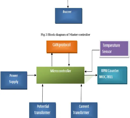
Fig 3 Block diagram of Master controller
Technology (IJRASET)
©IJRASET: All Rights are Reserved
1208
V.PROPOSEDSYSTEMANDRESULT
The required voltage for the board is obtained using transformers and it is given to the PIC board. The temperature is measured using lm35 sensor and its analog output is given to the PIC IC. The speed is measured using proximity sensor to the microcontroller via opto coupler. Then all the above mentioned factors are processed by the microcontroller using the
Fig.5.Circuit diagram for the proposed method
. VI. CONCLUSION
The values like Speed of the Motor (RPM), Current Drawn by the Motor, Temperature, and Efficiency are displayed in the LCD. CAN is more efficient than other wired protocols since it follows data based transmission. When load is applied to the motor, the current increases and the efficiency decreases.
REFERENCES
[1] Lu T. G. Habetler R. G. Harley A survey of available methods for evaluating in-service motor efficiency
[2] J. Hsu J. Kueck M. Olszewski D. Casada P. Otaduy L. Tolbert "Comparison of induction motor field efficiency estimation methods" IEEE Trans. Ind. Appl.</em> vol. 34 no. 1 pp. 117-125
[3] J. D. Kueck M. Olszewski D. A. Casada J. Hsu P. J. Otaduy L. M. Tolbert <em>Assessment of methods for estimating motor efficiency and load under field conditions
[4] W. Benning <em>Method of determining the efficiency of asynchronous motors and apparatus for carrying out the method.