Bending Analysis of CNT Reinforced Metal Matrix
Composite Rectangular Plates Using Higher Order
Shear Deformation Theory
K Kishan Kumar Patel1, J Suresh Kumar 2 1, 2
Department of Mechanical Engineering, JNTUH College of Engineering, J.N.T University, Hyderabad
Abstract: MMC have attracted the researchers because of its low weight and high strength. MMC are widely used in aerospace and automobile industry because of their high strength than steel. The present work aims to study the bending characteristics of simply supported FGCNT reinforced Metal Matrix Composite (FGCNT-MMC) rectangular plate subjected to transverse loads using Higher Order Shear Deformation Theory (HSDT).The properties of the chosen material are assumed to vary in the thickness direction in terms of volume fractions of the constituents. The material of interest here is Aluminum reinforced with CNT. The governing equations of motion and boundary conditions are derived using the principle of virtual work. Solutions are obtained for FGCNT plates in closed-form using Navier’s technique. Two different distributions of CNT are studies and the effect of various parameters such as side-to-thickness ratio, aspect ratio, and modulus ratio, the volume fraction exponent, and through-the-thickness on the deflections and stresses are studied. Further a computer program code is developed for the composite.
Keywords: Static Bending Behavior, FG-CNT Reinforced Composite Plates, Effective Material Properties, HSDT, Navier’s method.
I. INTRODUCTION
The immense need to develop lightweight and high-strength materials for improving energy-efficiency through the weight reduction of transportation carriers. Metal matrix composites (MMCs) generally consist of lightweight metal alloys of aluminum magnesium, or titanium, reinforced with ceramic particulate, whiskers, or fibres. The reinforcement is very important because it determines the mechanical properties, cost, and performance of a given composite. Composites reinforced with particulate (discontinuous types of reinforcement) can have costs
to unreinforced metals, with significantly better hardness, and somewhat better stiffness and strength. Continuous reinforcement (long fibre) can result in dramatic improvements in mechanical properties of MMC, but costs remain high. The application of continuously and discontinuously reinforced MMCs varies based on the design requirements. MMCs can be tailored to fulfil requirements that no other materials, including other advanced materials, can achieve. There are a number of niche applications in aerospace structures and electronics that capitalize on this advantage.
Aluminium and its alloys have attracted many researchers to choose it as a base metal in metal matrix composites [1]. Aluminium MMCs are widely used in aircraft, aerospace, automobiles and various other fields [2].Al matrix is widely used for CNT reinforced MMCs. Since the work by Zhong et al.[3]. The reinforcements should be stable in the given working temperature and non-reactive too. There are many manufacturing methods to obtain the CNT reinforced Al matrix composites (Al-CNT), amongst which, the powder metallurgy (P/M) technique could be considered as the most effective and economic one. Most of the current Al-CNT composites were fabricated by P/M and significant enhancement in stiffness and strength have been obtained [4-6]. A novel method to fabricate CNT-Al composites, which consists of a molecular level mixing process was proposed Cha et al.[7]. The CNT-Al metal matrix composites fabricated by this process improved the hardness due to a load transfer mechanism of the CNTs. The strength of CNT-Al metal matrix composites and investigated the relevant strengthening mechanisms involved in CNT-Al composites in order to produce optimized composites was studied George et al.[8].
matrix. The reinforcing phases such as powders, fibres and whiskers are generally incorporated into the metal matrices mostly by powder metallurgy, melting and solidification [21-22].
In the year 1991, Carbon Nanotubes (long, thin cylinders of carbon) were discovered by SumioIijima. These are unique for their size, shape, and remarkable physical properties. They can be seen as a sheet of graphite (a hexagonal lattice) rolled into a cylinder. They are less than 100 nanometres in diameter and can be as thin as 1 or 2 nm. Carbon nanotubes have a higher tensile strength than steel and Kevlar. Their strength comes from the sp² bonds between the individual carbon atoms, which is even stronger than the sp³ bond found in diamond.
There are several challenges in the fabrication of MMCs with CNT reinforcement. By far the most important challenge has been to obtain a uniform distribution of CNTs in the matrix. CNTs have large specific surface area up to 200 m2.g–1 and hence they tend to agglomerate and form clusters due to Vander Waals forces. In addition, the non-wetting nature of CNTs to most molten metals results in their clustering. Good dispersion of the reinforcement is a necessity for the efficient use of the properties as well as for obtaining homogeneous properties. CNT clusters have lower strength and higher porosity, and serve as discontinuities. Thus, they increase the porosity of the composite. The second important challenge is to ensure the structural and chemical stability of the CNTs in the metal matrix.
II. LITERATURE REVIEW
Werner Hufenbach, MaikGude, AndrzejCzulak, Bartlomiej Przybyszewski, Piotr Malczyk(2013), Investigation Of Mechanical Properties Of Aluminum Based Metal Matrix Composites At Elevated Temperatures[23]. Aluminum based metal matrix composites reinforced by continuous carbon fibre textiles (3D CF/Al-MMC) offer a high lightweight potential for usage under high thermo-mechanical loads. Main problem encountered in lightweight engineering for elevated temperatures is the change of the microstructure, and consequently drastic decrease of the stiffness and strength. There are reasonable presumptions, that this effect can be avoided by utilization of MMC with an appropriate reinforcement structure.
B. VijayaRamnath, C. Elanchezhian, RM. Annamalai, S. Aravind, T. Sri AnandaAtreya, V. Vignesh and C. Subramanian (2013) presented review on Aluminum MMC [ 24]. The adding reinforcements to the metal matrix showed the improvement in the stiffness, specific strength, wear, creep and fatigue properties compared to the conventional materials. This study presents the overview of the effect of addition on different reinforcements, fillers in aluminium alloy highlighting their merits and demerits. The mechanical properties like tensile strength, creep, strain, hardness, wear and fatigue were are also effected by using different reinforcements. K Mehar and S K Panda,(2016) presented Free Vibration and Bending Behaviour of CNT Reinforced Composite Plate using Different Shear Deformation Theory[25], the free vibration and the bending behaviour of carbo nnanotube reinforced composite plate are computed using three different shear deformation theories under thermal environment. The material properties of carbon nanotube and matrix are assumed to be temperature-dependent, and the extended rule of mixture is used to compute the effective material properties of the composite plate.
CNT-reinforced polymer composite beam under non-uniform thermal load [26]. Bending, buckling and free vibration behaviours of FG-CNT reinforced polymer composite beam under different non-uniform thermal loads have been analysed using finite element method. Extended rule of mixture is used to obtain effective material property of the composite. Parametric studies were carried out to investigate influences of the volume fraction of the carbon nanotube, functional grading and the nature of temperature variation on bending, buckling and free vibration characteristics. It is found that bending deflection reduces with increase in volume fraction of the CNT except for unsymmetrical functional graded beam.
Mechanical behaviour of laminated composite plates [27]. In the present study, the static, buckling, and free vibration of laminated composite plates is examined using a refined shear deformation theory and developed for a bending analysis of orthotropic laminated composite plates. These models take into account the parabolic distribution of transverse shear stresses and satisfy the condition of zero shear stresses on the top and bottom surfaces of the plates.
The FSDT is a highly efficient approach to analysing the moderate thick plates owing to its simplicity. In the FSDT, a constant transverse shear deformation is assumed through the entire thickness of the plate. This assumption does not satisfy the stress condition at the top and bottom of the plate. According to this shortcoming, the shear correction factor of the plate is a necessary
parameter in FSDT to provide the non-uniformed shear strain in transverse section [28]. However, the FSDT solutions become quite
unsatisfactory as the plate thickness–side length ratio increases [29]. In order to improve the accuracy of transverse shear stresses
and to avoid the introduction of shear correction factors, the HSDT has been proposed to study composite plates [30]. In this theory,
III. THEORETICAL FORMULATION
To formulate the Higher-Order shear deformation theory, two distributions of CNT are considered for the present work. The length, width and thickness of the FG-CNT reinforced plate are a, b and h respectively. The composite plate with two different configurations, UD (Uniformly distributed) and FGX (Functionally graded) are shown in the Figure 1.
Figure 1: Types of distributions of CNT in FG-CNT plate
The volume fraction of the CNT can be taken as below and hence the material properties of the Al-CNT can be calculated as below. , (UD)
, (FGX) (1)
where
in which is the fraction of mass of the CNTs, and and are densities of the matrix and CNTs. The effective Young's moduli and Poisson's ratio are calculated by:
(2)
where and are the elastic and shear moduli of the CNT. and are the corresponding properties of the isotropic matrix. Since the load transfer between the CNT and matrix is less than perfect, the CNT efficiency parameters are introduced to account for load transfer between the CNT and polymeric phases. are the volume fractions of the CNT and matrix, and their sum must be equal to 1, that is .
A. Displacement model:
In formulating the higher-order shear deformation theory, a plate of and is considered.
In order to approximate 3D-elasticity plate problem to a 2D one, the displacement components u (x, y, z), v (x, y, z) and w (x, y, z) at any point in the plate are expanded in terms of the thickness coordinate. The elasticity solution indicates that the transverse shear stress varies parabolically through the plate thickness. This requires the use of a displacement field, in which the in-plane displacements are expanded as cubic functions of the thickness coordinate. The displacement field which assumes w (x, y, z) constant through the plate thickness thus setting is expressed as: [32]
) , ( ) , , ( ) , ( ) , ( ) , ( ) , ( ) , , ( ) , ( ) , ( ) , ( ) , ( ) , , ( * 3 * 2 * 3 * 2 y x w z y x w y x z y x v z y x z y x v z y x v y x z y x u z y x z y x u z y x u o y o y o x o x o (3)
B. Elastic Stress-Strain Relations:
Since = 0, i.e., for the thin plate situation the transverse shear strains should tend to be zero, which become the constraint conditions as such the term is neglected in the virtual work statement and hence in the equation of motion. Consequently it amounts to neglecting the transverse normal stress. Thus we have, in theory, a case of plane stress [33]. For an FG-CNT reinforced composite laminate, the plane stress reduced elastic constants and the transformed plane stress reduced elastic constants will be same i.e., =
. The constitutive relations for FGCNT materials can be written as:
(4)
where,
, , , , are the stresses and , , , , are the strains with respect to the axes. are the plane stress reduced elastic constants in the plate axes that vary through the plate thickness and are given by:
, , ,
where,
= Young’s modulus of elasticity in the i direction.
= Poisson’s ratios that give strain in the j direction
due to stress in the i direction.
= shear moduli , and these are computed using Eq. (2).
C. Governing equations of Motion
The energy principle states that the work done by actual forces in moving through virtual displacements, that are consistent with the geometric constraints of a body is set to zero to obtain the equations of motion. This principle is useful in deriving governing equations, boundary conditions and obtaining approximate solutions by virtual methods. Energy principles provide another means to obtain the governing equations and their solutions. In the present work, the principle of virtual work is used to derive the equations of motion for FG-CNT plates. The governing equations of higher-order theory for the displacement model given in Eq. (3) will be derived using the dynamic version of the principle of virtual displacements, i.e.
0 ) ( 0
U V K dtT
(5)
Where,
U = Virtual strain energy
=
x x y y xy xy xz xz yz yz
dz dxdyh
h
A
2 / 2 /V = Virtual work done by applied forces = - qw0 dx dy
K = Virtual kinetic energy
U+V=total potential energy Where,
q = distributed load over the surface of the laminate.
0 = Density of plate material On substituting for U, V and K in to the virtual work statement in Eq. (5) and integrating through the thickness of the laminate, integrating by-parts and Collecting coefficients of each of virtual displacements uov0, w0, x, y,
u0*, v0*, x*, y* in a domain of any differentiation the statement of virtual work is obtained as governing equations of motion:
The resultants of force and moment can be related to the total strains by the following matrix:
* * * 0 0 * * * | 0 | 0 0 | | 0 | | K K D D B B A Q Q M M N N s b
t (6)
Where,
t t;N [N N N ] ] N N [N
N x y xy * *x *y *xy
N, N* are called the in-plane force resultants
t t;M [M M M ] ] M M [M
M x y xy * *x *y *xy
M, M* are called as moment resultants
t y t
Q Q [S S Q ] ;
] Q [Q
Q x y * x y *x *
Q, Q* denotes the transverse force resultants and also
t xy y x t xy y
x ] ; [ ]
[ 0 0 0 *0 *0 *0 *0
0
k [kxky kxy]t ;k* [kx* k*y k*xy]t [ ]t; [ xz0 yz0 x* y*]t *
y
x
The elements of matrices [A], [B], [D], and [Ds] are calculated using Eq. (6) and using the effective properties of the respective FG-CNT plate from Eq. (2).
IV. ANALYTICAL SOLUTIONS
Composite plates are generally classified by referring to the type of support used. The analytical solutions of the governing equations of motion for simply supported FGCNT plates are dealt here. Assuming that the plate is simply supported in such a manner that normal displacement is admissible, but the tangential displacement is not. Solution functions that completely satisfy the boundary conditions and the transverse mechanical load are considered using Navier method which on substitution in the governing equations of motion yields:
(7)
Solutions of Eq. (7) for each m, n = 1, 2, …… gives Umn, Vmn, Wmn, Xmn, Ymn,Umn* ,Vmn* ,Xmn* ,Ymn* which can be used to compute the
IV. RESULTS AND DISCUSSION
A. Comparative Studies
In this section, examples are presented and discussed to verify the accuracy of higher order shear deformation theory in predicting the deflections and stresses of simply supported functionally graded material plate. Aluminium is selected as the matrix. The material properties of which are as follows:
SWCNT (single-walled carbontubes) are taken as the reinforcements and its properties are:
, , and [34].
The values of volume fraction of CNT i.e., and the corresponding CNT efficiency parameters are listed in Table 1. It is assumed that the effective shear moduli
V*CNT η1 η2 η3
0.11 0.149 0.934 0.934 0.14 0.150 0.941 0.941 0.17 0.149 1.381 1.381
Convenience, the transverse displacement, in-plane and the transverse shear stresses are presented in non-dimensionalized form as:
, , , ,
and
( Present ) Type of distribution
0.11
10 UD 0.000332
FGX 0.000291
20 UD 0.005034
FGX 0.004452
0.14
10 UD 0.00031
FGX 0.00461
20 UD 0.00029
FGX 0.00442
0.17
10 UD 0.00031
FGX 0.00032
20 UD 0.000249
[image:7.612.194.425.259.318.2]FGX 0.003701
Table 2: Comparison of non-dimensionalized central deflection
Table 2 shows the comparison of non-dimensionalized central deflection, W for the CNTRC square plate with two cases UD and FG distribution and subjected to sinusoidal transverse load using higher- order theory with non-dimensionalized central deflection. For a particular volume fraction, the deflection is higher in case of FGX compared to UD, expect in the case of =0.11. Increase in
[image:7.612.39.578.329.641.2]B.Parametric Study
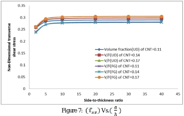
1)Effect of side-to-thickness Ratio: The variation of non-dimensionalized displacements and stresses for various side to thickness ratios ( / ) and for different volume fraction of CNT ( ) for the displacement model are shown in Figures 2 - 7 for two
[image:8.612.132.459.229.707.2]Figure 2 shows the variation of centre deflection with different volume fractions of CNT ( ) and with different side-to-thickness ratios for different distributions of CNT. It can be observed that the volume fraction of CNT has so much influence on the central deflection of the plates. Only 0.06 increase in the volume fraction of CNT leads to 26% decrease in central deflection for both the distributions of the CNT reinforced composite. It can also be observed that the deflection of UD-CNT reinforced composite plate is large compared to FGX-CNT reinforced composite because the type of distribution affects the stiffness of the plates. From this it is concluded that the reinforcements distributed near the top and bottom surfaces of more efficient than those distributed near the mid-plane.
Figure 2: Vs.
Figure 4: Vs.
[image:9.612.146.468.325.718.2]It can be observed that the volume fraction of CNT has little effect on stresses as the side-to-thickness ratio increases. Fig-3-5, it can be observed that , increases as the side-to-thickness ratio increases and decreases with the increase in side-to-thickness ratio for both the distributions of CNT.
Figure 5: Vs.
Figure 7: Vs.
2) Effect of Aspect Ratio: The effect of aspect ratios ( and volume fraction of CNT for displacement model for different
distributions of CNT on non-dimensional displacement and stresses are shown in figure 8-13. From figure 8 it can be observed that the central deflection decreases steeply with increase in the aspect ratio and the maximum deflection decreases with the increase in volume fraction for both the distributions. For FGX distribution, as the plate has rich CNT distribution at the top and bottom layers, the central deflection is less compared with the UD.
[image:10.612.147.467.79.281.2]The change in volume fraction does not have much influence on stresses as the maximum stress is almost same in all the volume fractions as shown in figure 9-13. From figure 9 it can noticed that the longitudinal stress decreases as the aspect ratio increases. At a particular aspect ratio, the value of longitudinal stress is higher for FGX compared to the UD. Figure 10 shows the increase in normal stress with the increase of aspect ratio upto 1 and then decreases. From figure 11 it can be observed that longitudinal shear stress increases with increase in aspect ratio upto 1 and then decreases. The shear stress is least for the volume fraction 0.17 with FGX distribution. For a particular value of aspect ratio, the value of shear stress is less in FGX compared to UD. Figure 12 shows the increase in shear stress upto the aspect ratio of 1.5. From Figure 13 it is observed that the transverse shear stress decrease as the aspect ratio increases.
[image:10.612.140.499.480.711.2]Figure 9: Vs.
Figure 10: Vs.
[image:11.612.145.463.91.264.2]Figure 12: Vs.
Figure 13: Vs.
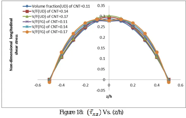
[image:12.612.153.476.71.413.2]3) Variation of stresses through-the-thickness: The variation of stresses in a FG-CNT reinforced composite plate through the thickness under sinusoidal load is as shown in Figures 14-18. The variation of stress is very less with the change in volume fraction compared to change in distribution. From the Figures 14-15, it can be observed that the in-plane longitudinal stress and the in-plane normal stress are compressive in the plate up to the mid-plane and then becomes tensile in the upper half of the plate. The maximum tensile and compressive stress can be seen on the top and bottom surfaces respectively. At a given z/h value, the value of stress in FGX distribution is less than UD as the distribution is rich on top and bottom surfaces for FGX. From Figure 16, it can be seen that the longitudinal shear stress is tensile in nature up to the mid-plane and then changes to compressive in nature thereafter. The transverse shear stresses and increases in a parabolic manner with a maximum value at mid-plane and then decreases. The maximum value shear stress occurs in the UD. For a particular value of (z/h), the value of shear stress is less for FGX distribution compared to UD.
[image:12.612.147.448.569.726.2]Figure 15: Vs. (z/h)
Figure 16: Vs. (z/h)
[image:13.612.145.458.69.734.2]Figure 18: Vs. (z/h)
V. CONCLUSIONS
A higher-order shear deformation theory was effectively developed to study the bending behaviour of simply supported CNT reinforced Metal Matrix composite plate without any transverse shear stress on top and bottom surfaces of plate. The required governing equations and boundary conditions are derived using the principal of virtual work. Navier’s type closed form is used to solve the governing equation of FG plate subjected to sinusoidal load. A comparative study is carried between the UD and FGX distributions of composite plate. The bending responses of functionally graded material plates mainly depends on the type of CNT distribution and volume fraction considered. The material properties vary in thickness direction and the stress distributions are smooth. The scope of the present study can be extended to experimental and numerical method to further study the bending behaviour of FG-CNT composites.
REFERENCES
[1] D.L. McDanels // Metall. Trans. A 16 (1985) 1105.
[2] B. Ralph, H.C. Yuen and W.B. Lee // J. Mater. Proc. Technol. 63 (1997) 339.
[3] Zhong R., Cong H., Hou P.X., 2003, Fabrication of nano-Al based composites reinforced by single-walled carbon nanotubes, Carbon, Letter to the Editor, 41(4),
848-851.
[4] A.M .K. Esawi, K. Morsi, A. Sayed, M. Taher, S. Lanka: Compos. Sci. Technol. Vol. 70 (2010), p. 2237.
[5] J.Z. Liao, M.J. Tan, I. Sridhar: Mater. Des. Vol. 31 (2010), p. S96.
[6] C.N. He, N.Q. Zhao, C.S. Shi, X.W. Du, J.J. Li, H.P. Li, Q.R. Cui: Adv. Mater. Vol. 19 (2007), p. 1128.
[7] Cha S.I., Kim K.T., Lee K.H., Mo C.B., Hong S.H., 2005, Strengthening and toughening of carbon nanotube reinforced alumina nanocomposite fabricated by
molecular level mixing process, ScriptaMaterialia, 53(7), 793-797.
[8] George R., Kashyap K.T., Rahul R., Yamdagni S., 2005, Strengthening in carbon nanotube/aluminium (CNT/Al) composites, ScriptaMaterialia, 53(10),
1159-1163.
[9] M. Zheng, K. Wu, C. Yao, Mater. Sci. Eng. A 318 (2001) 50.
[10] F. Wu, J. Zhu, Y. Chen, G. Zhang, Mater. Sci. Eng. A 277 (2000) 143.
[11] J.C. Viala, P. Fortier, G. Claveyrolas, H. Vincent, J. Bouix, J. Mater. Sci. 26 (1991) 4977.
[12] Y. Kagawa, E. Nakata, J. Mater. Sci. 11 (1992) 176.
[13] A. Oberlin, M. Endo, T. Koyama: J. Crys. Grow. 32 (1976) 335.
[14] M. Treacy, T.W. Ebbesen, J.M. Gibson: Nature 381 (1996) 678.
[15] H. Dai, E.W. Wong, C.M. Lieber, Science 272 (1996) 523.
[16] T.W. Ebbesen, H.J. Lezec, H. Hiura, J.W. Bennett, H.F. Ghaemi, T. Thio: Nature 382 (1996) 54.
[17] P.M. Ajayan, L.S. Schadler, C. Giannaris, A. Rubio: Adv. Mater. 12 (2000) 750.
[18] R.H. Baughman, A.A. Zakhidov, W.A. De Heer: Science 297 (2002) 787.
[19] E.T. Thostenson, Z. Ren, T.W. Chou: Composites Science and Technology 61 (2001)1899.
[20] Y.A. Kim, T. Hayashi, M. Endo, Y. Gotoh, N. Wada: J. Seiyama, ScriptaMaterialia 54 (2006) 31.
[21] H.Z. Ye, X.Y. Liu: J. Mater. Sci. 39 (2004) 6153.
[22] William D CallisterJr: Materials Science and Engineering, An Introduction, John Wiley & sons, Inc. (2006) 577.
[23] Werner Hufenbach, MaikGude, AndrzejCzulak, BartlomiejPrzybyszewski, PiotrMalczyk, Investigation Of Mechanical Properties Of Aluminium Based Metal
Matrix Composites At Elevated Temperatures, 15. - 17. 5. 2013, Brno, Czech Republic, Eu.
[24] B. VijayaRamnath, C. Elanchezhian, RM. Annamalai, S.Aravind, T. Sri AnandaAtreya, V. Vignesh and C.Subramanian, ALUMINIUM METAL MATRIX
[25] K Mehar and S K Panda, Free Vibration and Bending Behaviour of CNT Reinforced Composite Plate using Different Shear Deformation Theory, Materials Science and Engineering 115 (2016) 012014.
[26] K Mayandi and P Jeyaraj, Bending, buckling and free vibration characteristics of FG-CNT-reinforced polymer composite beam under non-uniform thermal load,
J Materials: Design and Applications 2015, Vol. 229(1) 13–28.
[27] BelkacemAdimTaharHassaineDaouadjiAberezak Rabahi1, A simple higher order shear deformation theory for mechanical behavior of laminated composite
plates, Int J AdvStructEng (2016) 8:103–117.
[28] Akini, J.E.: Analysis of layered composite using a high-order deformation. Comput. Struct. 27, 2–6 (1987). [29] Reddy, J.: Mechanics of laminated composite plates and shells. CRC Press, (2004).
[30] Phan, N.D.; Reddy, J.N.: Analysis of laminated composite plates using a higher-order shear deformation theory. Int. J. Numer. Methods Eng. 21, 2201–2219 (1985).
[31] M.H. Yas, N. Samadi, Free vibrations and buckling analysis of carbon nanotube-reinforced composite Timoshenko beams on elastic foundation, International
Journal of Pressure Vessels and Piping., Vol. 98, pp.119-128, 2012.
[32] Pandya B.N., Kant T. Finite element analysis of laminated composite plates using higher order displacement model, Composites Science and Technology, 1988,
Vol32:137–55.
[33] J. N. Reddy. Mechanics of laminated composites plates and shells, theory and analysis, second edition, (2004), pg.671-721.
[34] Zhu J, Yang J and Kitipornchai S 2013 Dispersion spectrum in a functionally graded carbon nanotube-reinforced plate based on first-order shear deformation