Modelling and Simulation of Solid Oxide Fuel
Cell for Distributed Generation Using Simulink
Devender Sharma1, Sushil Kumar2, Shiba Arora3
1
M.Tech student, 2Asstt. Prof
GTBK Institute of Engg. & Tech., Chhapianwali, Malout, Punjab, India
3
Asstt. Prof., JCDM college of Engg., Sirsa, India
Abstract- Fuel cell technology is a relatively new energy-saving technology that has the potential to compete with the conventional existing generation facilities. Among the various Distributed Generation or onsite generation or localized generation technologies available, fuel cells are being considered as a potential source of electricity because they have no geographic limitations and can be placed anywhere on a distribution system. Modeling of SOFC is done by using by using Nernst equation. In that the output power of the fuel cell can be controlled by controlling the flow rate of the fuels used in the process. The three phase PWM inverter to get the suitable form three phase output voltages for the grid connected applications. In this paper, design and modeling of Solid Oxide Fuel cell (SOFC) is discussed for the distributed generation applications. Modeling and simulations are carried out in MATLAB Simulink platform.
Keywords- Fuel cell, Distributed generation, inverter, and Solid oxide fuel cell (SOFC), Boost Converter, PI controller
I. INTRODUCTION
Fuel cells based DG system is considered an alternative to centralized power plants due to their nonpolluting nature, high efficiency, flexible modular structure, safety and reliability. At present, they are under extensive research investigation as the power source of the future, due to their characteristics. A fuel cell converts chemical energy directly to electrical energy through an electrochemical process. As opposed to a conventional storage cell, it can work as long as the fuel is supplied to it. There are many motivations in developing this method of energy generation and it needs further development to have a realistic system analysis combining various subsystems and components [1]. Among the various types of fuel cells discussed in the literature, PEMFC and SOFC fuel cells are in wide use and have been widely commercialized. A number of research have been undertaken in the modeling, control and performance of PEMFCs, which are best suited to mobile and residential applications. Because of their lower efficiency and dependence on pure hydrogen as fuel, they have not found much use in stationary power applications [1], [2]. SOFCs, which work at high temperatures, however, are ideal for DG applications, wherein power is generated at the load site itself. A suitable dynamic model of a fuel cell considering the electro-chemical thermodynamic process and electrical performance is necessary with respect to DG technology application of SOFC. In this respect, an SOFC under transient state was modeled and simulated by the author of [3], which included both electrochemical and thermal aspects of the cell performance treating fuel input as constant. The model was also not suitable for power system analysis. Following their work, the authors in [5] described a simulation model for a SOFC power plant, where the different plant sub-subsystems were modeled from a power system point of view. In their work, the FC operating temperature was assumed constant and the voltage drop due to ohmic losses were also considered. The authors approximated the electrochemical and thermodynamic processes using first order transfer functions. The model was also amenable to a power system analysis package. Later in [8], the authors included a fuel processor in their investigation and used their model to study the load tracking capability of the SOFC plant wherein it was suggested that the pressure of hydrogen and oxygen in the gas compartments of the anode and the
cathode should be restricted to 4 a kP under normal conditions and to 8 a kP under transient conditions. However, they did not
676
paper, the fuel cell has been taken up in detail and various concepts that result in the conversion of chemical energy to electrical energy have been dealt with. The operation of a fuel cell has been discussed with special emphasis on Solid Oxide Fuel Cells and various chemical equations that occur in the FC have also been discussed. Next, the mathematical model and the various equations pertaining to the fuel cells have been derived, followed by the development of the dynamic model of SOFC based DG system, in MATLAB/SIMULINK environment.
II. MATHEMATICALMODELOFSOFC
The following assumptions are made in developing the mathematical model of fuel cell stack: Fuel cell is fed with hydrogen and oxygen.
The gases considered are ideal, that is, their chemical and physical properties are not co-related to the pressure. Nernst equation is applicable.
Fuel cell temperature is stable at all times.
The electrode channels are small enough that pressure drop across them is negligible.
The ratio of pressures between the inside and outside of the electrode channels is sufficient to consider choked flow. Ohmic, activation, and concentration losses are considered.
The dynamic modeling of a Fuel Cell Distributed Generation (FCDG) system is an important problem that needs a careful study. To study the performance characteristics of FCDG systems, accurate models of fuel cells are needed. Moreover, models for interfacing the power electronic circuits in a FCDG system are also needed for designing controllers, which are required for the overall system to improve its performance and to meet certain operational requirements [14]. Concerning the system operational requirements, a FCDG system needs to be interfaced through a set of power electronic devices.
Fig.1. Block diagram of the Fuel cell distributed generation system
The performance of FCs is affected by several operating variables, as discussed in the following. Decreasing the current density increases the cell voltage, thereby increasing the FC efficiency. One of the important operating variables is the reactant utilization, UF, referring to the fraction of the total fuel (or oxidant) introduced into a FC that reacts electrochemically:
Where, H2qis the hydrogen molar flow.
High utilizations are considered desirable (particularly in smaller systems) because they minimize the required fuel and
oxidant flow, for a minimum fuel cost and compressor load and size. However, utilizations that are pushed too high result in significant voltage drops. The SOFC consists of hundreds of cells connected in series and parallel. Fuel and air are passed through the cells. By regulating the level, the amount of fuel fed into the fuel cell stacks is adjusted, and the output real power of the fuel cell system is controlled. The Nernst’s equation and Ohm’s law determine the average voltage magnitude of the fuel cell stack [18]. The following equations model the voltage of the fuel cell stack:
where:
No is the number of cells connected in series.
R is the universal gas constant. T is the temperature;
Ifo is the current of the fuel cell stack; F is the Faraday's constant.
III. DESIGN OF DC – DC BOOST CONVERTER
[image:4.612.152.470.277.396.2]In this work, the boost converter has been considered for providing a regulated dc output voltage at its terminals. DC–DC boost converter is the integral part of fuel cell power conditioning unit. The design of DC–DC boost converter and their controller plays important role to control power regulation particularly for common DC bus. The converter operates in the linear region operation of fuel cell stack. Beyond the linear region, the fuel cell cannot be operated as electrolyte membrane of fuel cell may get damaged. The main advantages of the boost converter include higher efficiency and a reduced number of components. The duty cycle has been varied at a high switching frequency to convert the unregulated voltage into a regulated supply. The values of inductor and capacitor have been chosen appropriately to reduce the ripples. However, the large inductance tends to increase the startup time slightly while small inductance allows the coil current to ramp up to higher levels before switch turns off. A simulink model of boost converter is shown in Fig. 2.
Fig.2. Simulink model of Boost converter
IV. DESIGN OF DC- AC CONVERTER
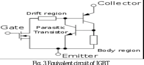
Since fuel cell (fc) generates dc output voltage, it must be inverted using a dc to ac for household application as well as for distributed generation. inverters can be either voltage source or current source inverters. in vsi, the dc source has negligible impedance and the terminal voltage remains almost constant with load variations. any short circuit across the terminals causes current to rise very fast, and to clear the faults, fast acting fuse links must be incorporated. the csi, on the other hand, is supplied with a controlled current from a high impedance dc source. here, the inverter output voltage is dependent on the load impedance and thus terminal voltage can change substantially with changes in the load. however, inherent protection against short circuits is provided in this topology, thus fault protection is not required. to obtain a sinusoid, filter circuits at the output can be used, however, this increases the cost and weight of the inverter and efficiencies also fall due to additional losses in the filter. the igbt is a semiconductor device with four alternating layers (p-n-p-n) that are controlled by a metal-oxide semiconductor (mos) gate structure without regenerative action. the equivalent circuit is shown in figure3
Fig. 3 Equivalent circuit of IGBT
[image:4.612.190.425.568.674.2]678
[image:5.612.148.461.111.227.2]controller has been designed for inverter under voltage controller mode using PI controller that adjusts the modulation index to maintain a constant voltage across the load.
Fig. 4 Control scheme for the IGBT Inverter
V. SIMULINK MODEL OF SOFC
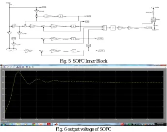
[image:5.612.134.478.393.666.2]The ac real power injection into the utility grid is considered to be the reference power for the fuel cell. The stack voltage and the reference power are used to determine the reference current which in turn is used to determine the fuel cell stack current. The fuel flow is proportional to the stack current. The partial pressure of hydrogen, oxygen and water are determined using the flow rates of hydrogen and oxygen. The stack voltage is based on the Nernst Equation which depends on the stack current and the partial pressures of the gas. The modeling of SOFC is carries out based on the assumptions made that the fuel cell temperature is made to be constant; the fuel cell gasses are ideal and the Nernst’s equation applicable to the cell. By Nernst’s equation output fuel cell dc voltage Vfc across stack of the fuel cell at current I is given by the Simulink Models of Fuel Cell System.
Fig. 5 SOFC Inner Block
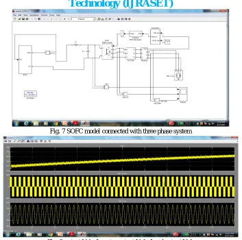
Fig. 7 SOFC model connected with three phase system
Fig. 8 output Vdc, Inverter output Vab, Load output Vab
[image:6.612.143.470.492.648.2]The fuel system designed in this work for distributed generated grid connected applications consists of the solid oxide fuel cell, Boost converter, three phase inverter and the load. The three phase inverter is selected because most of the loads are three phases in general. The overall simulink model diagram is shown in figure 9 and followed by the model Designs of the individual blocks of SOFC, converters. A Simulink model of PI controlled DC– DC boost converter based is shown in Fig.9.
680
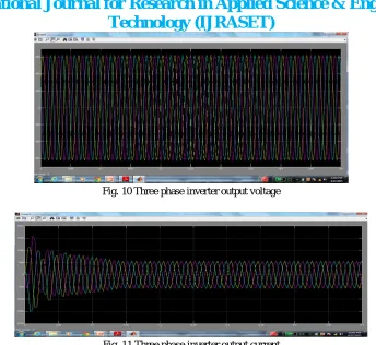
Fig. 10 Three phase inverter output voltage
Fig. 11 Three phase inverter output current
The DC–DC converter is an integral part of fuel cell power conditioning unit hence modeled PI boost converter has been used in SOFC based DG to maintain a constant voltage of 776 V output which is required as an input to inverter, irrespective of variation in the load and fuel cell terminal voltage. The PI controller minimizes steady state error to zero. The process of sensing the control variable and transformation of dimensionless measured quantities compared with reference signals.The change in duty cycle for varying load is obtained by controlling the suitable PI parameter values of voltage controller. The set parameters of PI controller are Kp and I K are 0.15 and 1.15 respectively. From the above simulation results it can be identified to meet the load changes in the power system can be effectively be controlled by incorporating the FC system as they are fed constant output voltages. The FC output can be controlled by controlling the internal parameters of the fuel cell.
VI. CONCLUSION
A dynamic model of SOFC based DG system has been developed in MATLAB /SIMULINK environment to supply power to an isolated load. Various power electronic interface topologies that convert the power generated by the FCs into a usable form have been discussed. A DC-DC PWM boost converter model is developed and interfaced to fuel cell to boost SOFC voltage to a
regulated dc voltage required for DC/AC PWM inverter to serve for an isolated load. A PI controller has been designed for
dc/dc converter that minimizes the steady state error to zero. A control strategy under voltage control mode using PI controller has been developed for three phase PWM inverter that interfaces the SOFCs to a three phase isolated load. Thus the developed model of SOFC based DG system can be used as a tool suitable for studying and for performing accurate analysis of most electrical phenomena that occur when it is interfaced to the isolated load. The proposed control strategy for this kind of distribution system helps in delivering the maximum power of fuel cell power source and makes the proper operation of each power source under power quality disturbances. Also the proposed control strategy is insensitive to the parameter variation in the distribution system network. The effectiveness of the proposed system can be verified by using the MATLAB/SIMULINK environment.
VII. ACKNOWLEDGMENT
Devender Sharma student of M.tech in GTBK Institute of Engg. & Tech., Chhapianwali, Malout, Punjab, India, had done his B.Tech degree from JCDMCOE, Sirsa.
REFERENCES
[1] I. El-Samahy, Ehab El-Saadany, “The Effect of DG on Power Quality in a Deregulated Environment”, Power Engineering Society General Meeting, June 2005, IEEE.
[2] Sh.Hosseinzadeh, M.A.Golkar, Sh.Shokri, A.Hajizadeh, “Reliability Improvement And Loss Reduction of Distribution System with Distributed Generation”, International Power System Conference (PSC2006), 13-15 Nov. 2006, Tehran-Iran.
[3] P.R. Khatri, Member, V.S. Jape, N.M. Lokhande, B.S. Motling, “Improving Power Quality by Distributed Generation”, The 7th International Power Engineering Conference (IPEC), DEC. 2005.
[4] Custom Power Technology Development, 1999. IEEE P1409 Distribution Custom Power Task Force 2. [5] Kwang Y. Lee, “The Effect of DG Using Fuel Cell under Deregulated Electricity Energy Markets”, IEEE 2006.
[6] Rahman S.: Fuel cell as a distributed generation technology. In Proceedings of IEEE power engineering society summer meeting, 2001. p. 551–2. [7] Z. Miao, M. A. Choudhry, R. L. Klein, and L. Fan, “Study of a fuel cell power plant in power distribution system—Part I: Dynamic model,” in Proc. IEEE PES General Meeting, Denver, CO, Jun. 2004.
[8] C. J. Hatziadoniu, A. A. Lobo, F. Pourboghrat, M. Daneshdoost, “A Simplified Dynamic Model of Grid- Connected Fuel-Cell Generators”, IEEE Transaction on Power Delivery, Vol. 17, No. 2, AprilL 2002.
[9] Kourosh Sedghisigarchi, Ali Feliachi,” Dynamic and Transient Analysis of Power Distribution Systems with Fuel Cells—Part II: Control and Stability Enhancement”, IEEE Transactions on Energy Conversion, Vol. 19, No. 2, JUNE 2004.
[10] Valery Knyazkin, Lennart S¨oder Claudio Canizares, “Control Challenges of Fuel Cell-Driven Distributed Generation”, Paper accepted for presentation at 2003 IEEE Bologna PowerTech Conference, June 23-26, Bologna, Italy.
[11] B. Delfino, F. Fornari, “Modeling and Control of an Integrated Fuel Cell-Wind Turbine System”, Paper accepted for presentation at 2003 IEEE Bologna PowerTech Conference, June 23-26, Bologna, Italy
[12] Kourosh Sedghisigarchi,Ali Feliachi, “Impact of Fuel Cells on Load-Frequency Control in Power Distribution Systems”, IEEE Transactions on Energy Conversion 2006.
[13] Rekha T. Jagaduri, Ghadir Radman, “Modeling and control of distributed generation systems including PEM fuel cell and gas turbine”, Electric Power Systems Research 77 (2007) 83–92.
[14] A. Hajizadeh, M.A. Golkar, A. Feliachi, “Power Management Strategy of a Hybrid Distributed Generation System”, International Journal of Distributed Energy Resources, Vol. 3, No. 2, April-June 2007.
[15] M.A. Golkar, A. Hajizadeh, “Fuzzy-Based Mitigation of Voltage Sag and Active Power Control in Distribution System Using Fuel Cell Distributed Generation”, International Power System Conference (PSC2006), 13-15 Nov. 2006, Tehran-Iran.