Volume 68– No.3, April 2013
Architecture for H.264 Intra Prediction Fast Mode
Decision Algorithm
Vimal Kumar Shrivastava
Research Scholar NIT Raipur Raipur, C.G., India
P. Muralidhar
Assistant Professor NIT Warangal Warangal, A.P., India
C. B. Rama Rao
Associate Professor NIT Warangal Warangal, A.P., India
ABSTRACT
The paper presents an architecture for fast mode decision algorithm in H.264/AVC for 4x4 intra-prediction. This algorithm is based on the inherent symmetry existing in the spatial prediction modes. This algorithm gives a faster way of calculating sum of absolute differences (SADs) for all modes of intra prediction. So, a significant computational savings can be achieved. Synthesis results confirmed that the proposed architecture is able to process HD videos (1280x720) at 30 fps as well as 60 fps and Full HD videos (1920x1088) at 30 fps in ASIC platform and maximum frequency achieved is 63 MHz.
Keywords
AVC, H.264, Intra Prediction, Inherent Symmetry, mode decision, SAD, HD videos, ASIC platform.
1.
INTRODUCTION
H.264/MPEG-4 Part10 AVC is the latest video coding standard developed jointly by the ITU-T Video Coding Experts Group (VCEG) and the ISO/IEC Moving Picture Experts Group (MPEG). The video compression efficiency achieved in H.264 standard is not a result of any single feature but rather a combination of a number of encoding tools. One of the tools is the intra prediction algorithm used in the baseline profile of H.264 standard [1]. Intra prediction algorithm generates a prediction for a Macroblock (MB) based on spatial redundancy. H.264 intra prediction algorithm achieves better coding results than the intra prediction algorithms used in the previous video compression standards. However, this coding gain comes with an increase in encoding complexity which makes it an exciting challenge to have a real-time implementation of H.264 intra prediction algorithm [1].
2.
H.264 INTRA FRAME PREDICTION
For the H.264 intra coding, it takes advantages of the small block size in spatial domain. These image blocks are coded based upon directional predictions, which are computed-extensive. For the luminance (luma) samples, intra prediction may be formed for each 4x4 block or for a 16x16 macroblock. There are a total of 9 prediction modes for each 4x4 luma block; 4 modes for a 16x16 luma block. The latest H.264 standard also defines 8x8 block and also has 9 prediction modes which are the same as those modes used in 4x4 block. Similarly, for chroma 8x8 block, another 4 prediction modes are used.
2.1
4x4 Luma Intra Prediction Modes
There are nine 4x4 luma prediction modes designed in a directional manner as shown in Fig 1(a). A 4x4 luma block consisting of the pixels a to p is shown in Figure 1(b). The pixels A to M belong to the neighboring blocks and are assumed to be already encoded and reconstructed and are
therefore available in the encoder and decoder to generate a prediction for the current MB. Each 4x4 luma prediction mode generates 16 predicted pixel values using some or all of the neighboring pixels A to M as shown in Figure 2. The arrows indicate the direction of prediction in each mode. The predicted pixels are calculated by a weighted average of the neighboring pixels A-M for each mode except Vertical, Horizontal and DC modes [2].
[image:1.595.326.543.306.429.2](a) (b)
Fig 1: Directions of nine 4x4 intra prediction modes and a 4x4 block with its neighboring pixels [3]
Fig 2: 4x4 luma prediction modes [4]
[image:1.595.324.538.457.626.2]3.
IMPLEMENTED
FAST
MODE
DECISION ALGORITHM
The proposed algorithm is based on the spatial symmetry in the intra prediction process and uses pixel to pixel correlation as the basis for obtaining a subset of candidate modes. This algorithm gives a faster way of calculating sum of absolute differences (SADs) for all modes of intra prediction. So, a significant computational savings can be achieved.
3.1
Inherent Symmetry in Intra-Prediction
Modes
[image:2.595.324.537.141.233.2]Fig. 3 depicts the inherent symmetry in the various intra-prediction modes. Assume that this figure shows the prediction blocks of all modes of the current block indexed with respective mode numbers. From this representation the pixel to pixel correlation can be easily observed in each mode. For example, in Mode 0 - the Vertical prediction mode, due to the symmetry, we can see that the pixels in each column will have the same predicted pixel value. Similarly, in Mode 1 - the Horizontal mode, the pixels in each row will have the same predicted value. Subsequently, such symmetry observations can be extended to all the different modes [5].
Fig 3: Inherent Symmetry and Pixel Correlation in different intra-prediction modes [5]
Now, consider eight 2x2 sub-blocks in the original 4x4 block X at different positions as shown in Fig.4. They are labeled as aj where j is an index to position of sub-block. Let mij
represent similar sub-block in ith prediction mode at jth
position. We may consider the same notation for the sub-block average also. Thus, for Mode 0 with Vertical symmetry, we can see that m01 is same as m03, and, m02 is same as m04.
Similar symmetry exists in all modes as summarized in Table1.
[image:2.595.319.543.270.365.2]Fig 4: 2x2 Sub-blocks [5]
Table 1. Inherent Symmetry in Intra-prediction modes [5]
3.2
Prediction Process
Using the above symmetry in different prediction modes, from Table 1, we try to simplify the intra prediction process as follows. We try to obtain a close measure to SAD cost function in each mode (which is just the sum of absolute differences between16 pixels in X and P) in terms of those sub-blocks which come under symmetry in respective prediction modes as listed in the Table 1 above.
In mode 0, the sum of absolute differences between a1 and m01; a2 and m02; a3 and m03; a4 and m04 gives the cost. However since m01=m03 and m02=m04 in mode0 due to the symmetry we can simply calculate the cost function as |a1 - m01| + |a2 - m02| + |a3 - m01| + |a4 - m02|, where |x| stands for the absolute value for x. Similarly cost is calculated in all other modes exploiting the existing symmetry in corresponding prediction mode as listed out in Table 1. The pixels which are not covered under symmetry (like in modes 3-8) are taken care of by replicating the pixel differences that are covered under symmetry. The fact that the intensity variations within a block are not so rapid from pixel to pixel and also that these neighboring pixels are similarly predicted from the same adjacent pixels justifies the assumption [5].
3.3
Pre-calculation Cost
Note that all of the mij measures can be calculated from 13
pixels A-M from neighboring blocks using the corresponding pixel values in respective positions in each prediction block depending on the mode. The cost function is simplified by using averages of sub-blocks instead of pixels directly. It is further simplified by the symmetry observed in Table 1, which brings down the number of ‘m’ measures that are to be pre-computed in each mode. As an example mode 0 requires only m01 and m02 to be computed as (A+B)/2 and (C+D)/2 respectively instead of 4 measures m01 to m04. Modes 2-4
[image:2.595.62.274.340.673.2]Volume 68– No.3, April 2013
15 measures are required to be computed in addition to 8 averages aj in the original block to calculate the cost function
for all modes. This is the total pre-calculation cost for a block. To further cut down the pre-calculation cost, we avoid divisions by considering only additions of pixels in sub-blocks rather than averages. This final pre-calculation cost is insignificant compared to the computational gain achieved [5].
4.
PROPOSED ARCHITECTURE
[image:3.595.311.533.77.251.2]The block diagram for spatial symmetry based algorithm of intra prediction process is shown in fig. 5.
Fig 5: Block Diagram of intra prediction unit
The proposed H.264 intra frame coder hardware is divided into two main parts; the mode decision part and prediction part. The mode decision hardware and the prediction hardware work in a parallel manner. There is one memory of size 256x 8 and one address generation unit, which generate addresses to access one 4x4 block (16 pixels) and its corresponding neighboring block (13 pixels) from memory. After the current 4x4 block and its neighboring pixels are loaded to the input register files (16x8), mode decision hardware starts to work on determining the best mode out of 9 modes based on the minimum SAD value and in parallel with mode decision hardware, prediction logic unit also starts to predict the 4x4 luma block by using equations specified in h.264 standard draft [7]. Finally, the output of mode decision unit selects the best predicted mode from all the 9 modes processed by prediction logic unit.
4.1
Architecture for Sub-Block Averages
Block
Fig. 6 shows the architecture for sub-block averages block, which calculates the 8 sub-block averages (ai ) as shown in
fig. 4. The input for this block comes from 16 registers each of 8-bits, which holds the value of 16 pixels of current 4x4 block.
Fig 6: Architecture for sub-block averages block
4.2
Architecture for Predicted Sub-Block
Averages Block
Fig. 7 shows the architecture for predicted sub-block averages block, which calculates the 15 predicted sub-block averages (mij ) as shown in Table 1. The input for this block comes
[image:3.595.50.280.226.374.2]from 13 registers each of 8-bits, which holds the value of 13 neighboring pixels of current 4x4 block.
Fig 7: Architecture for predicted sub-block averages block
4.3
Processing Element (PE)
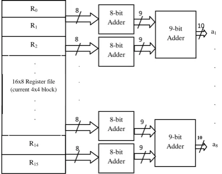
In fig. 8, architecture for processing element (PE) is shown, which calculate 9 SADs for 9 prediction modes of one 4x4 luma block. The one of the input for this is 8 sub-block averages aj where j is an index to position of sub-block and
the other input is 15 predicted sub-block averages mij where
mij represent similar sub-block in i th
prediction mode at jth position. ABS block gives the absolute value of output of subtractor block. 16x8 Register file (current 4x4 block) Current MB memory 56x8) 13x8 Register file (Neighbor pixels) Sub-block avgs (ai)
Predicted sub-block avgs (mij)
9 P E
Prediction Logic Unit Address Generation Unit Best Predicted MB C O M P A R A T O R Mode no 8-bit Adder 8-bit Adder Adder 8-bit Adder Adder 8-bit Adder Adder 9-bit Adder R0 R1 R15 R14
16x8 Register file (current 4x4 block)
R2 a1 a8 8 8 8 9 9 9 9 10 10 9-bit Adder 8 . . . . . . . . . . . . . . . . . . 9-bit
Adder m83
[image:3.595.320.537.378.535.2]Fig 8: Architecture for processing element (PE)
[image:4.595.367.493.332.503.2] [image:4.595.52.271.394.567.2]Example: for mode 0, the sum of absolute differences between a1 and m01; a2 and m02; a3 and m03; a4 and m04 gives the cost. However since m01=m03 and m02=m04 in mode 0 due to the symmetry we can simply calculate the cost function as |a1 - m01| + |a2 - m02| + |a3 - m01| + |a4 - m02|, which is nothing but the SAD0 .Similarly cost is calculated in all other
modes by this PE block.
4.4
Prediction Logic Unit
The prediction logic block consists of two blocks, equation generation block and equation assignment block. Input for this block comes from the 13 neighboring pixels of current 4x4 block and the outputs are prediction equations for all 9 modes. Architecture for this block is shown in fig. 9.
Fig 9: Architecture for prediction logic unit
4.4.1
Equation Generation Block
The standard formulae for different modes are transformed into pixel processing equations specified in h.264 standard draft [8]. For horizontal and vertical modes the neighboring reconstructed pixel values are directly assigned. DC mode is a simple average of the neighboring reconstructed pixels. For the remaining six modes all the equations are sorted to find out the unique set of equations by equation generation block, which result in 24 equations only [6].
Unique equations:
D1<= L D2<= (K+L+L+L+2) D3<= (K+L+1) D4<= (J+K+K+L+2)
D5<= (J+K+1) D6<= (I+J+J+K+2) D7<= (I+J+1) D8<= (M+I+I+J+2) D9<= (M+I+1) D10<= (A+M+M+I+2) D11<= (M+A+1) D12<= (M+A+A+B+2) D13<= (A+B+1) D14<= (A+B+B+C+2) D15<= (B+C+1) D16<= (B+C+C+D+2) D17<= (C+D+1) D18<= (C+D+D+E+2) D19<= (D+E+1) D20<= (D+E+E+F+2) D21<= (E+F+1) D22<= (E+F+F+G+2) D23<= (F+G+G+H) D24<= (G+H+H+H+2)
4.4.2
Equation Assignment Block
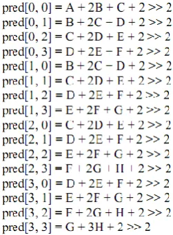
The predicted pixels are calculated by a weighted average of the neighboring pixels A-M for each mode except Vertical, Horizontal and DC modes. The prediction equations used in 4x4 Diagonal Down Left mode is shown in Fig. 10, where [y,x] denotes the position of the pixel in a 4x4 block (the top left, top right, bottom left, and bottom right positions of a 4x4 block are denoted as [0, 0], [0, 3], [3, 0], and [3, 3], respectively) and pred[y,x] is the prediction for the pixel in the position [y,x].
Fig 10: Prediction Equations for 4x4 Diagonal Down-Left Mode
As shown above, the prediction equations for Diagonal Down Left mode, other modes also have prediction equations. The equation generation block generates all those equations in the form of 24 unique equations except for vertical, horizontal and DC modes, because for horizontal and vertical modes the neighboring reconstructed pixel values are directly assigned and DC mode is a simple average of the neighboring reconstructed pixels. So, equation assignment block gives prediction equations for all 9 modes, for 6 modes with the help of 24 unique equations and for other 3 modes V, H and DC, directly by 13 neighboring pixels of current 4x4 block [5].
5.
IMPLEMENTATION
The architecture is defined in a hardware description language (VHDL) and synthesized by the Synopsys Design Compiler with 0.13µm standard cell library. The design specifications are shown in Table 2.
ai
mij
ai
mij
m
ij
ai
mij
subtracto r subtracto
r
10
10
subtracto r
subtracto r
10 10
ABS ABS ABS
10 ABS
10 10
10
10-bit Adde r
Bit adde r
11
11
10-bit Adde r
Bit adder
SADn 12
11-bit Adde r
ai
mij
R0
R1
R12
R11
13x8 Register file (Neighbor pixels)
R2
Equation Generatio n Block
Equation assignment
for 6 modes
Equation assignment
for remaining
3 modes V, H and DC
Equation assignment block
Prediction equations for all 9
modes 24
unique equations
Volume 68– No.3, April 2013
Table 2. Design Specifications
Algorithm Fast Mode Decision
Technology 0.13 µm
Application HD videos
Frame per second 30
Memory Requirement (256x8) to store current MB
Pixel parallelism 4 pixels
The performance analysis after compiling using the Synopsys Design Compiler is given in Table 3.
Table 3. Performance Analysis
Maximum Frequency 63 MHz
Critical Path Delay 15.10ns
Total cell area 219.54 K
Total dynamic power 1.4118 mW
Throughput 1059.60 x 106 Luma samples/sec
6.
EVALUATION AND RESULTS
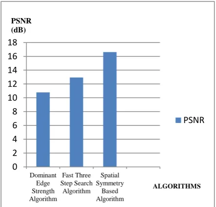
[image:5.595.57.278.506.718.2]The proposed algorithm is compared with two other algorithms three step search algorithm [6] and dominant edge strength algorithm [7] in matlab and observed that proposed algorithm is giving the best PSNR value as shown in fig. 11. Architecture for the proposed algorithm is implemented on FPGA Altera stratix II device and maximum frequency achieved is 153 MHz and also synthesized and simulated on synopsys tool and maximum frequency achieved is 63 MHz. In table 4, the proposed approach is compared with previous approaches for FPGA based implementation and in table 5, the proposed approach is compared with previous approaches for synopsys based implementation. Observation shows that the proposed architecture is able to process HD videos (1280x720) at 30 as well as 60 fps and Full HD videos (1920x1088) at 30 fps.
Fig 11: Comparison of PSNR for three algorithms
Table 4. Comparison with previous works for FPGA based Implementation
Design feature
Our
approach [9] [10] [6]
Device used
Altera Stratix II
Altera Stratix II
Xilinx Vertex II
Pro
Xilinx Vertex II
Pro Maximum
frequency
153 MHz 103 MHz
110 MHz
90 MHz
Maximum Target
Size
Full HD (1920 x 1088)
Full HD (1920 x 1088)
Full HD (1920 x 1088)
VGA frame (640x480)
Table 5. Comparison with previous works for synopsys based Implementation
Design
feature Our approach [11] [12]
Technology 0.13 µm 0.13 µm 0.18 µm
Maximum
frequency 63 MHz 54 MHz 61 MHz
Total cell area 219 k 84 k 72 k
Maximum Target
Size
Full HD (1920 x 1088)
SDTV (720x480)
HDTV (1280x720)
7.
CONCLUSIONS
In this paper, we present a fast mode decision algorithm for intra prediction in H.264 video coding. The proposed algorithm is based on the spatial symmetry in the intra prediction process and uses pixel to pixel correlation as the basis for obtaining a subset of candidate modes. The proposed hardware architecture for h.264/AVC intra prediction supports all the intra modes, calculates the sum of absolute differences (SADs) and decides the best intra 4x4 predicted macro block. This algorithm is also compared with two other fast mode decision algorithms in matlab and observed that this algorithm is giving the best PSNR value. Architecture is developed for this algorithm and synthesized and simulated on synopsys tool. Synthesis results confirmed that the proposed architecture is able to process HD videos (1280x720) at 30 as well as 60 fps and Full HD videos (1920x1088) at 30 fps and maximum frequency achieved is 63 MHz.
8.
REFERENCES
[1] Iain E. G. Richardson, “H.264 and MPEG-4 Video Compression – Video Coding for Next-generation Multimedia”, John Wiley & Sons, ISBN: 978-0-470-84837-1, 2003.
[2] Wiegand, T.; Sullivan, G.J.; Bjontegaard, G.; Luthra, A.; "Overview of the H.264/AVC video coding standard," Circuits and Systems for Video Technology, IEEE Transactions on , vol.13, no.7, pp.560-576, July 2003.
[3] Jia-Ching Wang; Jhing-Fa Wang; Jar-Ferr Yang; Jang-Ting Chen; "A Fast Mode Decision Algorithm and Its VLSI Design for H.264/AVC Intra-Prediction," Circuits and Systems for Video Technology, IEEE Transactions on , vol.17, no.10, pp.1414-1422, Oct. 2007.
[4] Shafique, M.; Bauer, L.; Henkel, J.; "A parallel approach for high performance hardware design of intra prediction
0 2 4 6 8 10 12 14 16 18
Dominant Edge Strength Algorithm
Fast Three Step Search Algorithm
Spatial Symmetry
Based Algorithm
PSNR
PSNR (dB)
in H.264/AVC Video Codec," Design, Automation & Test in Europe Conference & Exhibition, 2009. DATE '09. , pp.1434-1439, 20-24 April 2009.
[5] Sairam, Y.N.; Nan Ma; Sinha, N.; "A Novel Partial Prediction Algorithm for Fast 4x4 Intra Prediction Mode Decision in H.264/AVC," Data Compression Conference, 2008. DCC 2008 , pp.232-241, 25-27 March 2008.
[6] Sahin, E.; Hamzaoglu, I.; "An Efficient Hardware Architecture for H.264 Intra Prediction Algorithm," Design, Automation & Test in Europe Conference & Exhibition, 2007. DATE '07 , pp.1-6, 16-20 April 16-2007.
[7] Chao-Chung Cheng; Tian-Sheuan Chang; "Fast three step intra prediction algorithm for 4×4 blocks in H.264," Circuits and Systems, 2005. ISCAS 2005. IEEE International Symposium on , pp. 1509- 1512 Vol. 2, 23-26 May 2005.
[8] Jhing-Fa Wang; Jia-Ching Wang; Jang-Ting Chen; An-Chao Tsai; Anand Paul; "A novel fast algorithm for intra mode decision in H.264/AVC encoders," Circuits and Systems, 2006. ISCAS 2006. Proceedings. 2006 IEEE International Symposium on , pp.4, pp., 21-24 May 2006..
[9] La-Gou Wu; Duo-Li Zhang; Gao-Ming Du; Yu-Kun Song; Ming-Lun Gao; "A 4×4 pipelined intra frame decoder for H.264," Anti- , Security, and Identification in Communication, 2009. ASID 2009. 3rd International Conference on , vol., no., pp.332-335, 20-22 Aug. 2009.
[10]Diniz, C.M.; Zatt, B.; Agostini, L.; Susin, A.; Bampi, S.; "A real time H.264/AVC intra frame prediction hardware architecture for HDTV 1080P video," Multimedia and Expo, 2009. ICME 2009. IEEE International Conference on , vol., no., pp.1138-1141, June 28 2009-July 3 2009.
[11]Yu-Wen Huang; Bing-Yu Hsieh; Tung-Chien Chen; Liang-Gee Chen; "Analysis, fast algorithm, and VLSI architecture design for H.264/AVC intra frame coder," Circuits and Systems for Video Technology, IEEE Transactions on , vol.15, no.3, pp. 378- 401, March 2005.