Numerical Analysis of Flow Fields on Effect of
Inlet-Nozzle Diffuser for Hydrokinetic Axial
Flow Turbine
Aye Mya Maw *, Myat Myat Soe**
*
Mechanical Engineering Department, Mandalay Technological University Mandalay, Myanmar
**
Mechanical Engineering Department, Mandalay Technological University Mandalay, Myanmar
DOI: 10.29322/IJSRP.8.8.2018.p8020 http://dx.doi.org/10.29322/IJSRP.8.8.2018.p8020
Abstract- This research concentrates on the impact of diffuser and nozzle angles as changed parameters on flow velocity at diffuser passage. Diffuser length, nozzle length, throat diameter are fixed and diffuser and nozzle angles are varied 5̊ to 30̊ and 5̊ to 15̊ while the flow field analysis has been carried out using commercial software ANSYS CFX .The simulation results also show that diffuser and nozzle angles at (30̊,15̊) are the optimum angles that accelerates flow to the turbine. The velocity at these optimum angles are higher than other angles which cause the turbine can generate more power output. After getting the optimal inlet- nozzle diffuser design, numerical analysis for the designed hydrokinetic axial flow turbine with inlet-nozzle diffuser have been performed by using ANSYS CFX. This study also focuses on the flow velocity and pressure variation around the turbine due to the effect of inlet nozzle diffuser. Hence, the installation of diffuser around the conventional turbine significantly increases its power output capabilities. The proposed turbine design is intended to use at the irrigation channel so that turbine diameter and flow velocity is considered based on the selected location. According to the simulation results, incoming velocity 1.50 m/s at the throat of the turbine was increased up to 4.03 m/s and the preliminary designed turbine power output 210 W was increased to 288 W by installing inlet-nozzle diffuser to the hydrokinetic axial flow turbine.
Index Terms- Inlet-nozzle, Diffuser, Flow velocity, Hydrokinetic
I. INTRODUCTION
ydrokinetic turbines, also called free-flow turbines, generates electricity from the kinetic energy present in flowing water, rather than the potential energy from the head. The prime advantage of these type of turbine is, it doesn’t require heavy structure dam, and it provides power output directly from kinetic energy from flowing water. The same concept of horizontal axis wind turbine applies at a much smaller scale regarding river and stream flows with water as the acting medium. In each kinetic case involving axial turbines, power production was bounded by the Betz limit, bounding the efficiency of the unit to a maximum of 0.593. Gilbert and Foreman, developed the concept of augmenting a wind turbine with a diffuser, in annular fashion, negating the Betz limit and increasing the power production of the turbine [1]. Diffuser augmentation was applied to hydrokinetic turbines to improve performance with rotor disk sizes that were approximately two orders of magnitude smaller than typical large-scale wind turbines. Mehmood et. al. investigated numerous diffuser designs for tidal turbine application based on NACA hydrofoils [5]. Through the use of the hydrofoils, Mehmood et. al. was able to produce a 23.3% increase in velocity at the throat of the diffuser.Ohya et al. discovered hollow- structure diffuser is as viable as the shrouded form wind turbine for gathering and quickening the wind. Likewise, they found when utilizing a flange of proper height appended to the external periphery of the diffuser leave, a wonderful increment in wind speed. Aly Mo et. al performed about an improvement and investigation of 2-D axisymmetric CFD model of flanged diffuser [8].Inlet-nozzle diffuser is collecting-accelerating device which shrouds a hydrokinetic axial flow turbine. The present numerical investigation deals with the effect of low pressure region created by diffuser. Also in this analysis, numerical prediction of flow field around the turbine has been carried out with different diffuser and inlet-nozzle angles.
II. METHODOLOGY
A. Concept of Inlet-Nozzle Diffuser
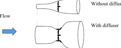
water flow velocity, a lower pressure would appear at the back of the turbine to act as a vacuum to suck the water flow and accelerate it towards the blades as shown in Fig 1.
Fig 1. Drop pressure effect of inlet-nozzle diffuser
The concept of diffuser is to increase the power output of hydrokinetic turbine by accelerating the flow velocity that approaches the turbine. To get optimum increased acceleration on the water speed, the pressure inside the hydrokinetic turbine should not be lower than the pressure at the wake of the diffuser. The diffuser is such that more water flows through the blade plane, and more power can be generated compared to a conventional 'bare turbine' of the same rotor blade diameter. Fig. 2 shows stream tubes passing through with and without diffuser turbine.
B. Hydrokinetic axial flow turbine design parameters
The energy flux contained in water streams depends on the density of the fluid, cross-sectional area and fluid velocity. The stream power is
The turbine extracted power andelectrical output power are
(2) P C P
t = p w
(3) P η η C P
e = p m g w
Where Pw is water stream power, Ptis turbine extracted power
,
Peis electrical output power and C is power coefficientp.
The rated water current velocity is 1.5 m/s, the mechanical and generator efficiency are 0.85 and 0.9, water density, ρ is 997 3
kg/m (at 25ºC).The length of the blade is equal to 0.3279 m. Subsequently, given the rotor design parameters (e.g., rotor diameter, tip speed, hydrofoil and water current velocity, among others), the main task of the blade design is to determine the chord and twist distributions along the span of the blade. Tip Speed Ratio (
λ
) is ratio of the speed of blade at its tip to the speed of incoming flow and is considered one of the important parameter.U (4)
v
w=
λ
Hence, power coefficient is the ratio of power produced by hydrokinetic turbine to power available in water stream:
(5) stream in water availabe Power by turbine produced Power = p C Low pressure Incoming Flow With diffuser Without diffuser Flow
Fig 2. Stream tubes passing through with and without diffuser turbine
(1) V A 2 1 P 3 w
C. Diffuser Augmented Hydrokinetic Axial Flow Turbine with Inlet-Nozzle
[image:3.612.203.404.136.243.2]The diffuser augmented hydrokinetic axial flow turbines extract more energy than conventional turbines alone. These turbines are more efficient due to flow manipulation and elimination of tip losses. The diffuser augmented hydrokinetic axial flow turbines are smaller in size for the same power. The designed turbine has three blades. The blades have SG-6041 hydrofoil profile. The rotor diameter is 656 mm. The tip gap was kept as small as practically possible i.e. 5-10 mm. The design specifications of the ducted wind turbine model are given in Table 1. Fig. 3 illustrates geometric parameters of inlet-nozzle diffuser.
[image:3.612.145.487.291.425.2]Fig 3. Geometric parameters of inlet-nozzle diffuser
Table 1. Design specifications of the hydrokinetic axial flow turbine with inlet-nozzle diffuser model
Sr.No Item Symbol Value Unit
1 Nozzle Length LN 0.2 m
2 Diffuser Length
D
L 0.61 m
3 Throat Diameter Dthroat 0.676 m
4 Rotor Diameter Drotor 0.656 m
5 Inlet-nozzle angle 5,10,15,20,25,30 degree
6 Diffuser angle 5,10,15 degree
III. NUMERICALANALYSIS
A. Simulation Process for Inlet-nozzle Diffuser
(i) Domain Specification and Meshing
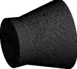
In this study, inlet-nozzle angles are varied at (5̊, 10̊, 15̊, 20̊, 25̊, 30̊) and diffuser angles are (5̊, 10̊, 15̊) respectively. Diameter of throat, diffuser length and inlet-nozzle length are fixed. Diffuser model is prepared using AutoCAD as shown in Fig.4. Numerical simulations for different angles of inlet-nozzle diffuser were performed to analyze flow characteristics by deploying an unstructured grid finite volume methodology using commercial CFD software (ANSYS CFX 17.0). The accuracy of results produced through a CFD calculation is reliant upon the mesh that is provided for analysis. Basic meshing techniques consist of a structured or unstructured mesh comprised of one of several element types. In this research, the mesh statistics are 106,608 nodes, 553,620 elements.Fig.4 (a) shows the geometry of inlet- nozzle diffuser and Fig.4 (b) shows the mesh of inlet- nozzle diffuser.
(a) Geometry (b) Mesh β
[image:3.612.332.462.582.699.2](ii) Boundary Condition
Boundary condition is velocity inlet of 1.50 m/s and pressure outlet of 1 atm as shown in Fig.5. k-ԑ turbulence model is used due to its good performance for predicting boundary layer separation with adverse pressure gradient.
(iii)Simulation Domain and Results
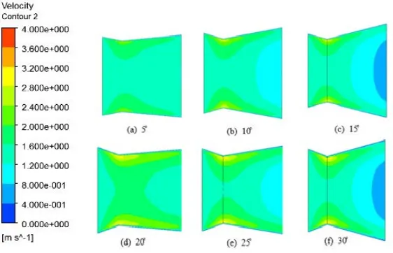
The CFD analysis provides a detailed information and visualization of water flow over inlet-nozzle diffuser. These outcomes approve the wonder of speed increment at diffuser throat when inlet-nozzle diffuser is utilized. Velocity of stream field is acquired from contours as shown in Fig.6 (a) to (f) and the velocity increase with inlet-nozzle angles.
The velocity variation of diffuser angle 10̊ and inlet - nozzle angle 5̊-30̊ are described in Fig. 7 (a) to (f).According to the figures, the velocity at the throat is higher than other locations.
Velocity inlet
Pressure outlet Wall
[image:4.612.166.461.302.475.2]Fig 5. Boundary condition of inlet- nozzle diffuser
Fig 6. Velocity contours for diffuser angle 5̊ and inlet- nozzle angle 5̊-30̊
[image:4.612.165.446.511.692.2]Fig.8(a) to (f) show velocity contours for diffuser angle 15̊ and inlet-nozzle angle 5̊-30̊.According to the velocity contours, the greater inlet-nozzle angle cause the higher inlet water velocity. It was observed from this analysis that inlet-nozzle can direct and provide smooth flow direction to the blades and also increase the velocity.
Nozzle angles
Diffuser angles
5̊ 10̊ 15̊
Maximum
velocity(m/s) velocity(m/s) Maximum velocity(m/s) Maximum
5̊ 1.61 1.69 1.6
10̊ 1.81 1.78 1.76
15̊ 1.89 2.63 1.97
20̊ 2.81 2.77 3.03
25̊ 3.5 3.53 3.52
30̊ 3.53 3.56 4.03
After performing the simulation for the diffuser design, it was found that diffuser with greater angle was shown the highest increment of water velocity because of low pressure. These simulation results show that the throat of inlet-nozzle diffuser has the highest flow velocity region which optimal position for the rotor blades in order to get an efficient design of diffuser augmented hydrokinetic axial flow turbine with inlet-nozzle. It is noted that nozzle and diffuser angle (30º, 15̊,) has the greatest velocity magnitude at the throat as shown in Table 2.This aspect results in a higher efficiency of the turbine.
B. Simulation Process for Hydrokinetic Axial Flow Turbine with Inlet-nozzle Diffuser
A small scale hydrokinetic axial flow turbine model is considered for the present numerical investigation. The rotor diameter of the turbine is 0.66 m for power output 200 W and the clearance between rotor and diffuser throat section is set to have 5 mm. The optimal design of inlet-nozzle diffuser (30º, 15̊) is attached to the turbine.
(i) Computational Domain and Mesh
[image:5.612.169.439.55.239.2]
(a) Geometry (b) Mesh Fig 8. Velocity contours for diffuser angle 15̊ and inlet-nozzle angle 5̊-30̊
[image:5.612.188.438.317.487.2] [image:5.612.362.482.636.729.2]
(c) Inlet and outlet Boundary condition (d) Computational Domain
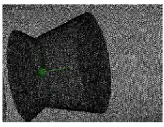
Fig.9 (a) shows the geometry of hydrokinetic axial flow turbine with inlet-nozzle diffuser. The mesh statistics of hydrokinetic axial flow turbine with inlet-nozzle diffuser are shown in Fig.9 (b) and it has 103, 945, 8 nodes and 123, 610, 64 elements. The dimension of outer cylindrical domain is four times of rotor diameter and length is eight times of rotor diameter. Inlet and outlet boundary condition and computational domain are as shown in Fig 9(c) and (d). An unstructured tetra mesh is formed in the flow domain for computations.
(ii)Boundary Conditions
In the computational domain entrance, a uniform velocity profile equal to 1.50 m/s was defined. Standard wall functions with no-slip boundary condition are applied on the surfaces of turbine, hub, shaft, inlet-nozzle diffuser, etc. At the domain output, pressure 1 atm was applied. Additionally, a general frozen rotor interface connection between the rotational and the stationary domain was used. The k-ԑ turbulence model has been shown to give good performance for flows with pressure gradients such as those appearing in the diffuser augmented hydrokinetic axial flow turbine flow configuration. Details of the boundary conditions are shown in Table 3.
Sr.No Item Symbol Value Unit
1 Density ρ 997
2 Pressure p 101.3 kPa
3 Rotor radius R 0.3279 m
4 Water velocity Vw 1.5 m/s
5 Rotor angular velocity
ω 27.22 rad/sec
7 Residual error - -
(iii) Simulation Domain and Results
Numerical simulation of flow field around hydrokinetic axial flow turbine is carried out by ANSYS CFX and the simulated results significantly predict the effect of diffusing passage and inlet-nozzle effect around the rotor blades as shown in Fig 10.
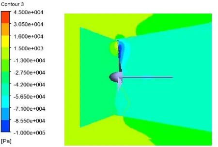
(a) Velocity Contour (b) Pressure Contour Inner rotating domain
Outer stationary domain
[image:6.612.42.502.62.158.2]Fig 9. Geometry model, computational domain and mesh of hydrokinetic axial flow turbine with inlet-nozzle diffuser
Table 3. Boundary conditions for Simulation Process
4
10 1× −
3 kg/m Velocity inlet
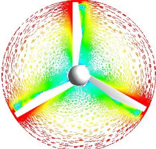
[image:6.612.187.416.346.492.2] [image:6.612.333.558.552.704.2]Fig. 10(a) describes velocity contour, (b) show pressure contour and (c) describes velocity vectors for side view and top view. According from the figures, the incoming velocity starts increasing at the inlet-nozzle and the velocity of the blade tip is higher than that of root. It can be observed from the pressure contour that pressure drop occur across the diffuser. This pressure drop indicates power extracted by the rotor causing its rotation.
[image:7.612.34.290.124.278.2]
(c)Velocity vector
Fig 10. Effect of inlet-nozzle and diffuser in the flow field around the turbine
From the analysis and study on the characteristic of the flow, it was realized that inlet- nozzle can direct and provide a better flow direction and streamlines towards the rotor blades and the diffuser creates the low pressure region that more water flows through the blade plane, and more power can be generated.
IV. RESULTS AND DISCUSSIONS
This research demonstrates the effect of inlet-nozzle and diffuser in flow field of the hydrokinetic axial flow turbine. It is observed that inlet-nozzle diffuser can give high velocity so that turbine power output is increased because power generated by turbine is directly proportional to the cube of velocity. From this flow simulation, it is found that when inlet-nozzle diffuser is applied on bare turbine, it produces smooth inlet flow towards the rotor blades and lower pressure region behind the turbine .Due to this pressure region gives significant increase in mass flow rate available for the turbine and also it produces 44 % increase in power output than bare turbine. Table. 4 shows results of simulation process.
Table 4. Results for CFD analysis
Turbine
Velocity(m/s) Power
Output (W)
inlet center outlet
Without
diffuser 1.8 2 2.2 210
With inlet nozzle diffuser
2.4 3 3.1 288
V. CONCLUSION
[image:7.612.385.538.125.271.2] [image:7.612.157.458.509.670.2]the water stream. According to the numerical results, the power output was increased from 200 W to 288 W due to the effect of inlet-nozzle diffuser for the hydrokinetic axial flow turbine. The findings of this research can provide more efficient way for small scale hydropower in remote area.
ACKNOWLEDGEMENT
The author wishes to express her deep gratitude to Dr. Sint Soe, Rector of Mandalay Technological University for his valuable suggestions and guidance. The author would like to thank to Dr. Htay Htay Win, Professor and Head of Mechanical Engineering Department, Mandalay Technological University, for her valuable guidance and comments for preparation of the research. And also special thanks to all teachers from Mechanical Engineering Department at Mandalay Technological University for their valuable supervision, guidance and encouragement throughout this paper. The author would like to express her deepest gratitude to her parents.
REFERENCES
[1] B. L. Gilbert, R. A. Oman and K. M. Foreman, "Fluid Dynamics of Diffuser Augmented Wind Turbines," Journal of Energy, vol. 2, no. 6, pp. 368-374, 1978 [2] K. M. Foreman, B. L. Gilbert and R. A. Oman, "Diffuser Augmentation of Wind Turbines," Journal of Solar Energy, vol. 20, no. 4, pp. 305-311, 1978. [3] B. L. Gilbert and K. M. Foreman, "Experimental Demonstrations of the Diffuser Augmented Wind Turbine Concept," AIAA Journal, vol. 3, no. 4, pp. 235-240, 1979.
[4] B. L. Gilbert and K. M. Foreman, "Experiments With a Diffuser-Augmented Model Wind Turbine," Journal of Energy Resource Technology, vol. 105, no. 1, pp. 46-53, 1983.
[5] N. Mehmood, Z. Liang and J. Khan, "Exploring the Effect of Length and Angle on NACA 0010 for Diffuser Design in Tidal Current Turbines," Applied Mechanics and Materials, vol. 201, pp. 438-441, 2012.
[6] N. Mehmood, Z. Liang and J. Khan, "Diffuser Augmented Horizontal Axis Tidal Current Turbines," Research Journal of Applied Sciences, Engineering and Technology, vol. 4, no. 18, pp. 3522-3532, 2012.
[7] N. Mehmood, Z. Liang and J. Khan, "CFD Study of NACA 0018 for Diffuser Design of Tidal Current Turbines," Research Journal of Applied Science, Engineering and Technology, vol. 4, no. 21, pp. 4552-4560, 2012.
[8] W. C. Schleicher, J. D. Riglin, Z. A. Kraybill and A. Oztekin, "Design and simulation of a micro hydrokinetic turbine," in 1st Marine Energy Technology Symposium, Washington, D.C., 2013.
[9] Y. Ohya, T. Karasudani, A. Sakurai, K.-i. Abe and M.Inoue, "Development of a shrouded wind turbine with a flanged diffuser," Journal of Wind Engineering and Industrial Aerodynamics, vol. 96, no. 5, pp. 524-539, 2008.
[10] D. L. Gaden and E. L. Bibeau, "A numerical investigation into the effect of diffusers on the performance of hydrokinetic turbines using a validated momentum source turbine model," Renewable Energy, vol. 35, no. 6, pp. 1152-1158, 2010.
[11] Chen, T.Y.; Liao, Y.T.; and Cheng, C.C. (2012) Development of small wind turbines for moving vehicles: Effects of flanged diffusers on rotor performance. Experimental Thermal and Fluid Science, 42, 136-142.
[12] Phillips, D.G.; Richards, P.J.; and Flay, R.G.J. (2000). CFD modelling and the development of the diffuser augmented wind turbine. In Proceedings of the Computational Wind Engineering, Birmingham, 189-192.
[13] Foreman, K.M. (1980). Preliminary design and economic investigations of diffuser augmented wind turbines (DAWT). Final Report, Research Department,Grumman Aerospace Corporation, Bethpage, New York and Solar Energy Research Institute, Colorado.
[14] Matsushima, T.; Takagi, S.; and Muroyama, S. (2006). Characteristics of a highly efficient propeller type small wind turbine with a diffuser. Renewable Energy, 31(9), 1343–1354.
[15] Hansen M. O. L., Sorensen N. N. & Flay R. G. J., Effect of Placing a Diffuser around a Wind Turbine, Wind Energy, 3, 2000, 207-213.
AUTHORS
First Author – Aye Mya Maw, Ph.D. Candidate, Mechanical Department, Mandalay Technological University [email protected].