SEISMIC PERFORMANCE OF SINGLE-BAY TWO-STOREY RC
FRAME UNDER IN-PLANE LATERAL CYCLIC LOADING
N. H. Hamid
1, M. I. Adiyanto
2and M. Mohamad
31
Institute Infrastructure Engineering and Sustainable Management, Universiti Teknologi MARA, Shah Alam, Selangor, Malaysia
2Faculty of Civil and Earth Resources, Universiti Malaysia Pahang, Lebuh Tun Razak, Gambang, Pahang, Malaysia 3
Faculty of Civil Engineering, Universiti Teknologi MARA, Shah Alam, Selangor, Malaysia E-Mail: [email protected]
ABSTRACT
A half-scale single-bay two-storey RC frame was designed in accordance to Eurocode 8 and constructed using ready mix-concrete by considering seismic load with Ductility Class Medium (DCM). Thetwo-storey moment resistant RC frame was constructed by preparing reinforcement bars caging, preparation of formwork, concreting and curing process. Then, the specimen was tested under in-plane lateral cyclic loading usinga double actuator starting from ±0.01% until ±2.25% with incremental of 0.25% drift. The total number of twenty-four cycles of drift was imposed to RC frame under control displacement method. The visual observations showed that a lot of cracks were concentrated at the corner and exterior beam-column joints where these were the points of transferred the load from top to the bottom of the structure. The ultimate lateral load of 158.48 kN in pushing direction and -126.09 kN in pulling direction was recorded at 2.25% drift. Based on the experimental result, elastic stiffness is 4.04kN/mm, secant stiffness is 1.14kN/mm, effective stiffness is 2.06kN/mm and ductility is 3.51. It can be concluded that the RC moment resistance frame able to withstand minor to moderate earthquake because the value of ductility is ranging between 3 to 6.
Keywords: ductility, equivalent viscous damping, hysteresis loops, lateral strength capacity, stiffness.
INTRODUCTION
West Malaysia is located between Australian and Eurasian tectonic plate meanwhile East Malaysia is situated between Eurasian and Philippine tectonic plates [1]. These plates are moving towards East and West Malaysia with velocity of 70mm/year. Even though Malaysia is not categorized as high seismicity but moderate earthquake can strike Malaysia in the future due to active movement of these major tectonics plate. Furthermore, most of the buildings in Malaysia were designed using non-seismic code of practice where there is no consideration for earthquake loads. Therefore, the future buildings in East Malaysia especially Sabah required to design the earthquake resistant using based isolation system, shear wall and moment resisting frame using current seismic code of practice such as Eurocode 8. Therefore, the main purpose of this research is to determine the seismic performance of single-bay two-storey moment resisting RC frame under in-plane cyclic loading under Ductility Class Medium (DCM).
Malaysia constructions industry is still facing some challenges in adapting the seismic codes of practice into the design stage as it might increase the construction cost and it will increase the sales/market price of the commercial buildings. Most of the buildings in Malaysia followed British Standard where there is no consideration on any seismic/earthquake loading in the design details. Many RC buildings in Malaysia were constructed using soft storey mechanism where there are open spaces at ground floor which make these buildings vulnerable to any earthquakes events. Up to date, only Penang Bridge was built to cater seismic vibrations in Malaysia [2] and Kuala Lumpur City Centre was designed to cater for wind load [3].
In this research, a single bay two-storey RC frame was constructed in the heavy structural laboratory using cast in-situ concrete and designed using Eurocode 8. The construction of the sample is carried out using stage by stage method also known as bottom to top method starting with the foundation and up to the highest roof floor. The main purposes of this study are to determine the seismic performance of RC frame under In-plane lateral cyclic loading through experimental work in Heavy Structural Laboratory Faculty of Civil Engineering, UiTM Shah Alam. A half scale single-bay of two-storey frame will be designed according to Eurocode 8 for Peak Ground Acceleration (PGA = 0.3g). Eurocode 8 provides sufficient percentage of reinforcement bars in the column, beam, beam-column joints and floor slab. Most of the RC buildings in Malaysia were designed in accordance to BS 8110 (British Standard) where there is no provision for earthquake load at all. These buildings are skeptical to damage and collapse if moderate or major earthquake strike any part of East and West Malaysia. Therefore, the safety of RC buildings in Malaysia is still questionable under severe earthquake loading. Most of the precast school buildings in Malaysia will survive under weak earthquake excitations with PGA = 0.08g but will not survive under PGA = 0.2g [4]. Thus, the new building need to be designed using Eurocode 8 to cater for moderate or major earthquake.
performance and characteristics of the structures, it is essential to calculate the stiffness, lateral strength capacity, over strength, ductility and equivalent viscous damping [5]. Figure-1 shows the system characteristics of a structure which need to evaluate based on the experimental work in the laboratory. Therefore, the main purpose of this study is to calculate these parameters for the single bay double-storey moment resisting frame under in-plane lateral cyclic loading. The detailing of the design, experimental set-up, analysis of results, discussions and conclusions will be discussed in the following sections.
Figure-1. Characteristics of a structure [5].
DESIGN OF RC FRAME
Figure-2 shows isometric view together with dimensions of one-half scale prototype moment resisting RC frame which had been constructed on the foundation beam (5450×1800×300 mm). The height of each floor is 1650 mm with column’s size of 200×200 mm. The top level of RC frame was constructed with slab thickness of 200 mm with a series of four holes. Meanwhile, the first and second floor were only bare frame without any in-fill of masonry brick or precast wall panel. Proper detailing of beam-column joint is very important because it is vital part in RC frame which designed to cater for lateral load with closed spacing of stirrup and with higher amount of longitudinal reinforcement bars. The moment resisting reinforced concrete frame was designed using Eurocode 8 with Peak Ground Acceleration (PGA=0.3g) and classified as Ductility Class Medium (DCM).
Figure-2. Isometric view of one-half scale RC frame.
Figure-3 shows the detailing of corner beam-column joint of moment resisting RC frame with closed spacing of stirrup of 60 mm between them. The main bars of the column consist of the two inner loops which designed to increase the area of confined concrete and reduce the damages of column and beam-column joint during moderate or severe earthquakes. All the longitudinal main and shear reinforcement bars were designed using high yield strength steel with fy=500 MPa.
According to Eurocode 8, the high yield steel can resist higher lateral load and lateral displacement as compared to the mild steel. Therefore, it also can avoid the fracture and bucking of the main bars and stirrups during earthquakes.
Figure-3. Detailing of a corner beam-column joint.
According to Eurocode 8, the development length and flexural strength of the corner beam-column joint is given by the following equation 1 [6]:
ℎ =
7.
𝛾𝑅𝐷 𝑦 + .8𝑣 (1)
Where db is the develop length of bar, hc is the
height of cross-section column, fctm is the compressive
strength of the concrete, fyd is the yield strength of the
bars, RD is the partial safety factor and vd is the
normalized axial force ratio on column. As specified in Eurocode 8, the minimum development length of the corner beam-column joint is 10db. The effective joint area,
Aj is the area resisting the shear within the joint and is
contributed by the framing members in the considered direction of loading. The depth of the joint, hj is taken as
equal to the depth of the column, hc and bc is the breadth
of the column. The minimum width of the joint, bj as
specified in Eurocode 8 is bc+0.5hc for the effective area
of the joint.
The horizontal shear reinforcement for the corner joint as specified in the Eurocode 8 is given in equation 2:
𝐴𝑗ℎ𝑓𝑦ℎ = 𝛾𝑅 𝐴𝑠2𝑓𝑦 − .8𝑣 (2)
Where Ajh is the area of shear reinforcement bars,
As2 is the area of reinforcement at bottom of the beam and
EXPERIMENTAL SET-UP AND TESTING
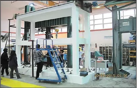
[image:3.595.315.547.135.280.2]After the design stage was completed, the specimen was constructed on the strong floor according to the dimensions as shown in Figure-1. The moment resisting frame was constructed on the foundation beam which bolted to the strong floor so that it would not move or uplift during testing under quasi-static in-plane lateral cyclic loading. The construction process included the preparing reinforcement bars cages together with formwork, pouring of the ready mixed concrete, curing process and dismantle of the formworks. Figure-4 shows the overall view prototype of moment resisting RC frame which were ready for testing after painting it with white colour water based.
Figure-4. The specimen was ready for testing.
[image:3.595.55.284.268.413.2]The prototype of half-scale single-bay two-storey reinforced concrete frame was tested under in-plane cyclic loading using control displacement method. A double actuator with 500 kN capacity load cell was attached to reaction frame. A total number of nine linear potentiometers which labelled as LVDT were used to measure the lateral displacement of specimen and uplift of the foundation beam during testing. Most of the linear potentiometers were installed at critical region of RC frame where the maximum displacement and potential crack are expected to occur such as at beam- column joint. Figure 5 shows the locations of all the LVDTs at left hand side of the RC frame and foundation beam. All the LVDTs, load cell and strain gauges were connected to the data logger for recording the lateral movement of the frame, lateral load and strain in the reinforcement bars. LVDT1 and LVDT2 were positioned at top of the specimen and parallel to the load cell which attached to the reaction frame anchored to the strong floor. Meanwhile, LVDT3 and LVDT4 were placed at the center of beam-column joint of the second floor. LVDT5 and LVDT6 were located at bottom of the column where it is expected that the occurrence of the plastic hinge zone. LVDT7 and LVDT9 were positioned vertically on top of the foundation beam for measuring any uplift and LVDT8 was placed on the left hand side of the foundation beam to measure it’s sliding during testing. Before start testing the specimen under in-plane lateral cyclic loading, all the equipment and instruments such as linear potentiometers,
strain gauges and load cell need to be calibrated in the laboratory.
Figure-5. Locations of LVDTs on the RC frame.
After the calibration process completed, the specimen was initially tested at ±0.01% and ±0.1% to make sure that all the instruments and equipment were functioned very well and recorded all the measurements in pulling and pushing directions accurately and correctly. Next, the specimen was tested again starting from ±0.2%,±0.25%, ±0.5%, ±0.75%, ±1.00%, ±1.25%, ±1.50%, ±1.75%, ±2.00% and ±2.25% drift. Two cycles of loading were tested for each drift in pushing and pulling forces. Figure-6 shows the loading regime for moment resisting frame which was comprised of 24 successive cycles with two cycles for each drift starting from 0.2% until 3.00%. The double actuator was stopped after testing each drift for inspection of structural damages such as hairline cracks, spalling of concrete covers, falling of the concrete blocks, buckling and fractured of main bars and shear reinforcement bars. All the hairline cracks and crack propagations were marked with blue and red markers. The width and length of the cracks were measured using Vernier Caliper and cloththreads.
Figure-6. Loading regime using control displacement method under target drift.
RESULTS AND DISCUSSIONS
Visual observation on structural damages
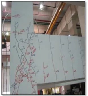
[image:3.595.309.544.552.686.2]identification mode of failures and classification of damages with respect of drift. Visual observation of the cracks especially at the main structural components such as columns beams and beam-column joints need to be captured using camera and recorded the movement of the specimen using cam-recorder. While testing, several types of cracks can be observed such as shear crack, hairline crack, diagonal crack, horizontal crack and vertical crack. Based on the visual observation on the specimen during testing, no cracks appear during the first four cycles of loading under initial drifts of ±0.2% and ±0.25%. At ±0.75% drift, vertical crack at beam and shear crack at beam-column joint were started to appear. From the visual observations, most of the cracks were occurred in pushing and pulling directions of the tension zones. Figure-7 shows the cracks patterns on the beams, columns and corner beam-column joints of single-bay two-storey RC frame in pushing and pulling directions when subjected to in-plane lateral cyclic loading. The hairline cracks marked in blue colours were occurred during pulling directions and hairline cracks marked in red colours were occurred during pushing directions. Most of the vertical cracks were observed in the four beams, whereas the horizontal cracks were observed in the columns and the diagonal cracks were observed at the first and second floors of the corner beam-column joints.
Figure -7. Hairlines cracks were observed on the columns, beams and corner beam-column joints.
Figure-8 shows the visual observation of diagonal cracks pattern specifically occurred at first floor of corner beam-column joints closed to the LVDT3 at ±1.75% drift and ±2.25% drift. At ±0.75% drift, vertical crack on beam and diagonal crack on corner beam-column joint were observed during testing. It can be observed that as the number of percentage drift increasing, the size of the cracks width increases along with the length of the cracks propagations [7].
Figure-8. The diagonal cracks at corner beam-column joint at the first floor.
[image:4.595.348.504.417.587.2]Figure-9 shows the another hairline cracks in longitudinal direction of the first floor of corner beam-column joint in pushing and pulling directions starting from ±0.75% drift until ±2.25% drift. Most of the diagonal cracks were concentrated at the corner beam-column joints where it is the point of transferring the lateral load from the double actuator from the beam and column to the beam-column joint where the lateral and vertical load were met. The diagonal cracks were occurred due to insufficient of diagonal reinforcement bars provided at this joint.
Figure-9. Diagonal cracks observed at corner joint.
column-foundation interface causing the opening and closing gap of shear cracks. Figure-11 shows the horizontal shear cracks on the column due to the in-plane lateral cyclic loading imposed to the specimen. This column experienced tension and compression zones when applied the lateral force in pushing and pulling directions. The horizontal shear cracks occurred the shear reinforcements were insufficient in the column either as spiral or inner bars. The seismic performance of RC columns could be significantly improved by continuous spiral reinforcement as a result of its adequate ductility and energy dissipation capacity [8].
Figure-10. Vertical flexural cracks on the beam.
Figure-11. Horizontal shear cracks on the column.
Figure-12 shows diagonal cracks at top corner of second floor and spalling of concrete cover at -2.0% drift occurred at column and floor slab at top of second floor of RC frame. Diagonal cracks and spalling of concrete occurred due to insufficient of transverse and longitudinal reinforcement bars in the column causing the reduction of confined concrete area to counter higher lateral cyclic loading than designed. According to research that had been conducted by Lu et al. [9], by adding diagonal reinforcement bar along the column gives good effect to the joint and increase the confined concrete area. Based on the overall visual observation, beam-column joints suffered severe structural damage at first floor compared to second floor because second floor level is fix to the steel plate and rigid due to presence mass concrete block
at top of the second floor. Figure-13 shows the spalling of concrete at the bottom corner of top beam-column joint which occurred at +2.0% drift.
Figure-12. Diagonal cracks at corner joint.
Figure-13. Spalling of concrete at bottom corner joint.
Hysteresis Loops
From the data of hysteresis loops, the seismic performance of structural behavior of single-bay RC frame can be evaluated in terms of lateral strength, ductility, stiffness and equivalent viscous damping. Figure-14 shows the hysteresis loops of LVDT1 starting from ±0.01% drift until ±2.25% drift which located at top of the RC frame. It is situated parallel to the center of load cell of double actuator which attached to the reaction frame. The maximum lateral drift is +2.25% which equivalent to 76.92mm and the maximum lateral load was recorded by load cell is 158.48 kN in pushing direction.
Figure-15 shows the hysteresis loops for LVDT3 which located at the center of beam-column joint at first floor of RC moment resisting frame. The maximum recorded lateral load recorded by load cell is 158.48 kN and the lateral displacement at this position when applied +2.25% drift applied is 33.74 mm.
Figure-15. Hysteresis loops for LVDT 3.
Meanwhile, Figure-16 shows the hysteresis loops for LVDT5 which placed at the bottom column at column-foundation beam interface where the location of plastic hinge zone (PHZ) is expected to occur. The recorded lateral displacement at +2.25% drift is 2.72 mm and maximum lateral load was 158.8 kN. It can be concluded that the maximum recorded lateral load was 158.48 kN and the lateral displacement is decreasing as the effective height of the column is decreasing. The hysteresis loops of LVDT1 is similar to LVDT2, LVTD3 is similar to LVDT4 and LVDT5 is similar to LVDT6. The others LVDT7, LVDT8, LVDT9, LVDT10 and LVDT11 were recorded very small lateral displacement with respect with lateral load.
Figure-16. Hysteresis loops for LVDT5.
Lateral strength capacity
Figure-17 shows the skeleton of load versus displacement under in-plane lateral cyclic loading in pushing and pulling direction starting from ±0.01% up to ±2.25% drift. Maximum strength was attained at ±2.25% drift in pushing direction. The specimen behaves in elastic behavior starting from ±0.01% drift until ±0.75%
drift and started to yield before completely fail at ±2.25% drift. The specimen continued to resist higher load and survive till ±2.25% drift until there is no strength left in the structure. The yield lateral displacement (Δy) in
pushing direction was occurred at ±0.75% drift with the
recorded lateral displacement (Δy= 22.04mm), the yield
lateral load is Fy= 106.05 kN and the yield lateral load in
pulling direction is Fy= -99.7 kN. The ultimate lateral
displacement is Δult= 76.92 mm and ultimate lateral load is
Fult=158.48kN in pushing direction and in pulling direction
is Fult= -126.09 kN which occurred at ±2.25% drift. All
these parameters will be used for calculating the elastic stiffness, secant stiffness, effective stiffness and displacement ductility which will be discussed in the following section.
Figure-17. Lateral strength capacity of the specimen.
Stiffness RC frame
Stiffness of structure can be defined as the ratio of the applied lateral load divided by the yield lateral displacement. There are three types of stiffness when a structure subjected to lateral load such as elastic stiffness (Ke), secant stiffness (Ksec) and effective stiffness (Keff).
The elastic stiffness (Ke) of structures indicates that the
initial stiffness which occurs in the elastic limit and the secant stiffness (Ksec) happens within the elastic regions [10]. The design seismic base shear (Vd) of the structures
can be determined by multiplying the effective stiffness (Ke) with the target lateral displacement (d). The equation
for elastic stiffness is defined in equation 3, secant stiffness in equation 4, effective stiffness in equation 5 and seismic base shear capacity is calculated using equation 6, respectively [10];
𝐾 = 𝑦
∆𝑦 (3)
𝐾𝑠 =∆ −∆−𝑦𝑦 (4)
𝐾 =∆ (5)
𝑉 = 𝐾 . ∆ (6)
direction however in pulling direction the stiffness only start decrease at ±0.5% drift. According to Hamid and Mohamed [11] as the target drift increase, the stiffness of the specimen should decrease. Stiffness also related to the lateral strength of the structure which is the stiffness will decrease when the structure losses its strength. Table-1 shows the calculated results for all the three stiffness parameters (Ke, Ksec and Keff) for the single bay RC frame
in pulling and pushing directions for the 1st and 2nd cycles
for the hysteresis loops which recorded by LVDT1. It can be concluded that the value of Keff lies between Ke and
Ksec. The average design seismic base shear capacity for
this moment resisting frame is 157.75 kN which will used as the basis for the static push-over analysis. The effective dampings of the structures are designed based on the base shear capacity and location of the structures at the hazard map of the selected place.
Table-1. Three types of stiffness for RC frame.
Stiffness (kN/mm)
Pushing direction Pulling direction
1st cycle 2nd cycle 1st cycle 2nd cycle
Kelastic 4.81 3.83 3.63 4.04
Ksecant 0.96 1.14 0.76 0.94
Keff 2.06 1.90 2.03 1.95
Vb (kN) 164 kN 151 kN 161 kN 155 kN
Ductility RC frame
Ductility is the ability of a material to undergo permanent deformation through elongation or bending at room temperature without fracturing [12]. Ductility can be calculated based on the plotted graph such as strain ductility (µ) for stress-strain relationship, displacement
ductility (µ) for load-displacement relationship, rotation ductility (µ) and others. For the purpose of this study, the
displacement ductility (µ) is calculated based on the load versus displacement graph as recorded by LVDT1. The displacement ductility can be determined by finding the ratio of the ultimate displacement (ult) over the yield
displacement (y). The ductility of the structure is very
important to determine in order to expect the survivality of any particular buildings or infrastructures under moderate or strong earthquake excitations. The equation of displacement ductility (µ) can be calculated using
equation 7 as given below:
𝜇∆=∆∆
𝑦 (7)
Table-2 tabulated the values of displacement ductility in pushing and pulling directions for the 1st and 2nd cycle of hysteresis loops. Based on the current seismic code of practice such as Eurocode 8, the value of
displacement ductility should be ranging between 3 ≤ µ ≤
6 to achieve the Ductility Class Medium (DCM). Maximum lateral displacement can be obtained from LVDT1 and divided by the yield displacement for calculating displacement ductility. The maximum value of ductility of this specimen is 3.54 in pushing direction and 3.51 in pulling direction at ±2.25% drift. In seismic design, close spaced of stirrup or shear reinforcement spacing to provide good confinement of concrete and large amount of longitudinal bar is essential in order to have higher ductility [13, 14, 15, 16].
Table-2. Displacement ductility for the specimen.
Displacement ductility
Pushing direction Pulling direction
1st cycle 2nd cycle 1st cycle 2nd cycle ult (mm) 76.92 77.28 -62.18 -62.04
y (mm) 21.75 22.04 -27.46 -20.24
µ 3.54 3.51 2.26 3.07
Equivalent viscous damping
Equivalent viscous damping [EVD] is defined as the ability of structure to dissipate energy during earthquake and reduce the structural damages by adding either active or passive damper to the structures [17]. From the hysteresis loops which obtained from experimental work, the amount of energy dissipated in one cycle of deformation can be calculated by the area of one loop (ED) and elastic strain energy (ESO) is determined by
the area under the triangle at maximum lateral load and displacement. The equation for the equivalent viscous damping is derived based on Chopra [18]:
eq = 𝜋𝐷
𝑜 (8)
on the result, the value of equivalent viscous damping for first cycle is higher compared to the second cycle. This is due to the fact that more energy is required to resist lateral force with stiffness elastic of Kelastic = 4.81 kN/mm in first
cycle as compared to Kelastic=3.83 kN/mm in second cycle.
Furthermore, the first cycle represents the initial strike of the earthquake which usually required more energy as compared to aftershock of the earthquake vibration which represents by second cycle.It can be concluded that the overall seismic performance of the structures depends on the demand capacity which come from the earthquake excitations at particular seismic hazard map and the capacity curve of the structures which depends on ductility classification. According to Eurocode 8, there are three class of ductility mainly DCL (Ductility Class Low), DCM (Ductility Class Medium) and DCH (Ductility Class High). These ductility classes will determine the level of capacity curve for each structure [19].
Figure-18. Equivalent viscous damping for first and second cycle of each drift of the hysteresis loops.
CONCLUSIONS AND RECOMMENDATIONS Based on the visual observation, experimental result and data interpretation, the conclusion can be drawn as follows:
a) Based on the visual observation on single bay RC frame, there are three types of cracks which are diagonal cracks occurred at beam-column joints, flexural cracks observed on surface of beams and shear cracks detected on columns.
b) The ultimate lateral strength and lateral displacement recorded at LVDT1 are 158.8kN and 76.92 mm, respectively which reached at +2.25% drift in pushing direction.
c) The value of elastic stiffness is 4.81 kN/mm, secant stiffness is 0.96 and effective stiffness is 2.06 for the first cycle in pushing direction.
d) Displacement ductility of RC moment resisting frame is 3.54 in pushing direction for 1st cycle which lies
within the minimum range of ductility (3≤µ≤6) for a
structure to survive under moderate to severe earthquake while the value of ductility in pulling direction is 3.51.
e) The highest value of equivalent viscous damping is 7.67% from first cycle at 0.5% drift and 4.36% from second cycle at 0.1% drift.
f) 6.The moment resisting of RC frame which designed according to Eurocode 8 under DCM (Ductility Class Medium) be able to resist the earthquake excitation with PGA=0.3g and satisfied the seismic performance parameters such as stiffness, ductility and equivalent viscous damping.
g) It is recommended that the damaged of moment resisting RC frame to be repaired and retrofitted using CFRP, steel plate, steel angle and enlargement of the damage columns.
ACKNOWLEDGEMENTS
The authors would like to thank the Fundamental Research Grant Scheme from Ministry of Higher Education (MOHe), Putrajaya, Malaysia with Ref. No.: 600-RMI/FRGS 5/3 (0091/2016), Research Management Institute (RMI) and Institute for Infrastructure Engineering, Sustainability and Management, Universiti Teknologi Mara, Shah Alam, Malaysia for funding and provide the facilities to conduct this research work.
REFERENCES
[1] Simons W. J. F., Socquet A., Vigny C., Ambrosius B. A. C., Haji Abu S., Promthong Subarya, C., Sarsito D. A., Matheussen S., Morgan P. & Spakman W. 2007. A decade of GPS in Southeast Asia: Resolving Sundaland motion and boundaries, Journal of Geophysical Research: Solid Earth, 112(B6).
[2] David C. 2016. Planning, design and construction of the Second Penang Bridge, Proceedings of the Institution of Civil Engineers - Bridge Engineering, ISSN No. 1478-4637, 169(4): 260-270.
[3] Charles H.T., Udon H. and Leonard, M.J. 1997. Design of the world’s tallest buildings Petronas Twin Towers at Kuala Lumpur City Centre, The Structural Design of Tall Buildings, John Wileys and Sons, Ltd. 6: 245-262.
loading , Safety and Seismic Engineering V, Vol. 134, WIT Press, pp 827-837.
[5] Hamid, N.H. Saleh, S.M. and Anuar, S.A. (2014), Seismic performance of double-unit form building under in-plane lateral cyclic loading, Structures under Shock and Impact XIII, Vol. 141, ISSN No: 1743-3509, pp 467-472.
[6] Uma, S.R. and Sudhir, K.J. (2006), Seismic design of beam-column joints in RC moment resisting frames - review of codes, Journal of Structural Engineering and Mechanics, 23)5), pp579-597.
[7] Patil, S.S., Konapure, C.G. and Manekari, S.S., (2013), A study of R.C.C. beam column junction subjected to quasi-static (monotonic) loading, IOSR Journal of Mechanical and Civil Engineering, ISSN No. 2320-334X, 6(5), pp61-714.
[8] Mohammad A., Azlan A., Abdul Rahman M.S., Mahmood M.T., Iman F., Reza H. 2014. Seismic performance of RC beam-column connection with continuous rectangular spiral transverse reinforcement for low ductility class. The Scientific World Journal, Hindawi Publishing Corporation, Volume 2014, Article ID802605, 12 pages.
[9] Lu X., Urukap T.H., Li S., Lin F. 2011. Seismic behavior of interior RC beam-column joints with additional bars under cyclic loading. Earthquakes and Structures. 3(1): 37-57.
[10]Priestley M.J.N.; Calvi G.M., Kowalsky M.J. 2007. Displacement-based seismic design of structures. IUSS Press, Pavia, Italy, ISBN No: 88-6198-000-6, p.721.
[11]Hamid N.H. and Mohamed N.M. 2013. Seismic assessment of a full-scale double-storey residential house using fragility curve. Elsevier Science Direct, Procedia Engineering. 54, pp. 207-221.
[12]David P.R. 2014. The mechanical properties of stainless steel, Southern Africa Stainless Steel Development Association (SASSDA). Stainless Steel Information Series No. 3, p. 8.
[13]Ghani K.D. and Hamid N.H. 2013. Experimental Investigation on a non-seismic precast RC beam-column exterior joint under quasi-static lateral cyclic loading. Safety and Seismic Engineering V, Vol. 134, WIT Press, pp. 827-837.
[14]Hamid N.H.A. 2014. Seismic Performance of Beam-Column Joints in Reinforced Concrete Buildings Subjected to Reversible Vertical Cyclic Loading. Malaysian Journal of Civil Engineering. 22(2): 263-290.
[15]Hamid N.H. and Masrom M.A. 2012. Seismic performance of wall-slab joints in Industralized Building System (IBS) under out-of-plane reversible cyclic loading. IACSIT International Journal of Engineering and Technology. 4(1): 26-33.
[16]Hamid N.H.A., Hadi N.D.A., Ghani K.D.A. 2013. Seismic Retrofitting of Beam-Column Joint Using CFRP and Steel Plate. World Academy of Science, Engineering and Technology International Journal of Civil, Structural, Construction and Architectural Engineering. 7(12).
[17]Symans M.D. and Constantinou C.C. 1998. Passive fluid viscous damping systems for seismic energy dissipation. ISET Journal for Earthquake Technology, Paper No. 382, 35(4): 185-206.
[18]Chopra A.K. 2011. Dynamics of Structures: Theory and Application to Earthquake Engineering, Fourth Edition, ISBN No: 10:0132858037, Prentice-Hall.