Copyright © 2015 by McGraw-Hill Education. All rights reserved. Except as permitted under the United States Copyright Act of 1976, no part of this publication may be
reproduced or distributed in any form or by any means, or stored in a database or retrieval system, without the prior written permission of the publisher.
ISBN: 978-0-07-182765-2 MHID: 0-07-182765-X
The material in this eBook also appears in the print version of this title: ISBN: 978-0-07-182764-5, MHID: 0-07-182764-1.
eBook conversion by codeMantra Version 1.0
All trademarks are trademarks of their respective owners. Rather than put a trademark symbol after every occurrence of a trademarked name, we use names in an editorial fashion only, and to the benefit of the trademark owner, with no intention of infringement of the trademark. Where such designations appear in this book, they have been printed with initial caps.
McGraw-Hill Education eBooks are available at special quantity discounts to use as premiums and sales promotions or for use in corporate training programs. To contact a representative, please visit the Contact Us page at www.mhprofessional.com.
Information has been obtained by McGraw-Hill Education from sources believed to be reliable. However, because of the possibility of human or mechanical error by our sources, McGraw-Hill Education, or others, McGraw-Hill Education does not guarantee the
accuracy, adequacy, or completeness of any information and is not responsible for any errors or omissions or the results obtained from the use of such information.
TERMS OF USE
This is a copyrighted work and McGraw-Hill Education and its licensors reserve all rights in and to the work. Use of this work is subject to these terms. Except as permitted under the Copyright Act of 1976 and the right to store and retrieve one copy of the work, you may not decompile, disassemble, reverse engineer, reproduce, modify, create derivative works based upon, transmit, distribute, disseminate, sell, publish or sublicense the work or any part of it without McGraw-Hill Education’s prior consent. You may use the work for your own noncommercial and personal use; any other use of the work is strictly
prohibited. Your right to use the work may be terminated if you fail to comply with these terms.
THE WORK IS PROVIDED “AS IS.” McGRAW-HILL EDUCATION AND ITS LICENSORS MAKE NO GUARANTEES OR WARRANTIES AS TO THE ACCURACY, ADEQUACY OR COMPLETENESS OF OR RESULTS TO BE
OBTAINED FROM USING THE WORK, INCLUDING ANY INFORMATION THAT CAN BE ACCESSED THROUGH THE WORK VIA HYPERLINK OR OTHERWISE, AND EXPRESSLY DISCLAIM ANY WARRANTY, EXPRESS OR IMPLIED,
INCLUDING BUT NOT LIMITED TO IMPLIED WARRANTIES OF
About the Author
Bobbi Sandberg is a small business consultant and retired CPA who has been a trainer, instructor, and teacher of all things computer in the Pacific Northwest for more than 40 years. She has “played” with computers since they occupied entire rooms and required perforated paper tape and punch cards. Today, she teaches hardware and software classes, solves hardware and software issues for a number of clients, and keeps networks
functional on a regular basis. Bobbi is the author or coauthor of several computer books, including QuickBooks 2015: The Small Business Guide, Quicken 2015: The Official Guide, Quicken 2014: The Official Guide, Microsoft Office 2013 QuickSteps, and
Computing for Seniors QuickSteps.
About the Technical Editors
Randal Nollan has been working with technology since the late 1970s when he wrote his first program on pink punch cards. Randal joined the U.S. Navy in 1980 as an Aviation Ordnanceman and retired in 2001. During that time, he maintained the dBase III
vaccination database for the squadron corpsman and was always in the thick of
maintaining the token ring network, computers, and terminals they had at the time. He graduated from Skagit Valley College CIS (networking) and MIT (programming) in 2003. He worked in Internet tech support from 2003 to 2005 and has since been working in computer repair for a local telephone company on Whidbey Island, Washington. In his spare time, he enjoys the outdoors by fishing, crabbing, bicycling, camping, and hunting. Indoor fun includes playing with anything tech related, remodeling his home, and making wine from any fruit that lands on his doorstep; some time he may even stop working and drink it.
Dwight Spivey is the author of more than 20 books on computers and technology and has happily lent his expertise as a technical editor to several more titles. Dwight is happily married to Cindy, and they reside on the Gulf Coast of Alabama along with their four children. He studies theology, draws comic strips, and roots for the Auburn Tigers in his ever-decreasing spare time.
Van Aguirre is an information technology specialist who has broad experience in the field. Since the late 1990s, he has developed and taught courses in networking and multimedia technology, computing security, computer crime forensics, IT risk
management, IT business continuity, and disaster recovery planning. Working with other IT professionals, he has planned and managed the implementation of evolving
Contents
Acknowledgments Introduction
Part I Network Basics
Chapter 1 What Is a Network?
Local Area Network
Baseband vs. Broadband
Packet Switching vs. Circuit Switching Cables and Topologies
Media Access Control Addressing
Repeaters, Bridges, Switches, and Routers Wide Area Networks
Protocols and Standards Clients and Servers
Operating Systems and Applications Chapter 2 The OSI Reference Model
Communications Between the Layers Data Encapsulation
Horizontal Communications Vertical Communications Encapsulation Terminology The Physical Layer
Physical Layer Specifications Physical Layer Signaling The Data Link Layer
Addressing
Routing Fragmenting
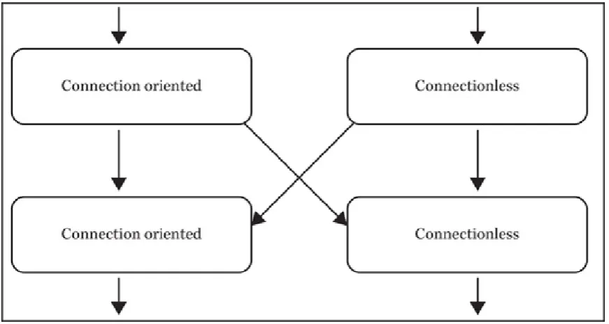
Connection-Oriented and Connectionless Protocols The Transport Layer
Protocol Service Combinations Transport Layer Protocol Functions Segmentation and Reassembly Flow Control
Error Detection and Recovery The Session Layer
Dialog Control Dialog Separation The Presentation Layer The Application Layer
Part II Network Hardware
Chapter 3 Network Interface Adapters
NIC Functions NIC Features
Full Duplex Bus Mastering Parallel Tasking
Wake-on-LAN or Wake-on-Wireless-LAN Selecting a NIC
Protocol
Transmission Speed Network Interface Bus Interface Bottlenecks ISA or PCI?
Hardware Resource Requirements Power Requirements
Server vs. Workstation NICs
Chapter 4 Network Interface Adapters and Connection Devices
Repeaters Hubs
Passive Hubs
Repeating, Active, and Intelligent Hubs Token Ring MAUs
Hub Configurations The Uplink Port Stackable Hubs Modular Hubs Bridges
Transparent Bridging Bridge Loops
Source Route Bridging
Bridging Ethernet and Token Ring Networks Routers
Router Applications Router Functions Routing Tables
Windows Routing Tables Routing Table Parsing
Static and Dynamic Routing
Selecting the Most Efficient Route Discarding Packets
Packet Fragmentation Routing and ICMP Routing Protocols Switches
Routing vs. Switching Virtual LANs
Layer 3 Switching
Multiple-Layer Switching Chapter 5 Cabling a Network
Cable Properties
Cabling Standards
Data Link Layer Protocol Standards Coaxial Cable
Thick Ethernet Thin Ethernet Cable Television Twisted-Pair Cable
Unshielded Twisted-Pair Category 5e
Cat 6 and 6a Cat 7
Connector Pinouts Shielded Twisted-Pair Fiber-Optic Cable
Fiber-Optic Cable Construction Fiber-Optic Connectors
Chapter 6 Wireless LANs
Wireless Networks
Advantages and Disadvantages of Wireless Networks Types of Wireless Networks
Wireless Applications The IEEE 802.11 Standards
Media Access Control Chapter 7 Wide Area Networks
Introduction to Telecommunications WAN Utilization
Selecting a WAN Technology PSTN (POTS) Connections Leased Lines
Leased-Line Types Leased-Line Hardware Leased-Line Applications ISDN
ISDN Services
ISDN Communications ISDN Hardware
DSL
Switching Services
Packet-Switching Services Circuit-Switching Services Frame Relay
Frame-Relay Hardware Virtual Circuits
Frame-Relay Messaging ATM
The Physical Layer The ATM Layer
The ATM Adaptation Layer ATM Support
SONET
Chapter 8 Server Technologies
Purchasing a Server
Server Clustering
Using Hierarchical Storage Management Fibre Channel Networking
Network Storage Subsystems Chapter 9 Designing a Network
Reasoning the Need Seeking Approval
Designing a Home or Small-Office Network Selecting Computers
Selecting a Networking Protocol Choosing a Network Medium Choosing a Network Speed Designing an Internetwork
Segments and Backbones
Distributed and Collapsed Backbones Backbone Fault Tolerance
Selecting a Backbone LAN Protocol Connecting to Remote Networks Selecting a WAN Topology Planning Internet Access Locating Equipment Wiring Closets Data Centers Finalizing the Design
Part III Network Protocols
Chapter 10 Ethernet Basics
Ethernet Defined Ethernet Standards
Ethernet II IEEE 802.3
CSMA/CD
Collisions Late Collisions Physical Layer Guidelines
10Base-5 (Thick Ethernet) 10Base-2 (Thin Ethernet)
10Base-T or 100Base-T (Twisted-Pair Ethernet) Fiber-Optic Ethernet
Cabling Guidelines
Exceeding Ethernet Cabling Specifications The Ethernet Frame
The IEEE 802.3 Frame The Ethernet II Frame
The Logical Link Control Sublayer The SNAP Header
Full-Duplex Ethernet
Full-Duplex Requirements Full-Duplex Flow Control Full-Duplex Applications
Chapter 11 100Base Ethernet and Gigabit Ethernet
100Base Ethernet
Physical Layer Options Cable Length Restrictions Autonegotiation
Gigabit Ethernet
Gigabit Ethernet Architecture Media Access Control
The Gigabit Media-Independent Interface The Physical Layer
Ethernet Troubleshooting Ethernet Errors
100VG-AnyLAN
The Logical Link Control Sublayer The MAC and RMAC Sublayers
The Physical Medium–Independent Sublayer The Medium-Independent Interface Sublayer The Physical Medium–Dependent Sublayer The Medium-Dependent Interface
Working with 100VG-AnyLAN Chapter 12 Networking Protocols
Token Ring
The Token Ring Physical Layer Token Passing
Token Ring Frames Token Ring Errors FDDI
FDDI Topology
Part IV Network Systems
Chapter 13 TCP/IP
TCP/IP Attributes TCP/IP Architecture
The TCP/IP Protocol Stack IP Versions
IPv4 Addressing Subnet Masking
IP Address Registration Special IP Addresses Subnetting
Ports and Sockets TCP/IP Naming TCP/IP Protocols
IP
Chapter 14 Other TCP/IP Protocols
IPv6
IPv6 Addresses
IPv6 Address Structure Other Protocols
ICMP UDP TCP
Chapter 15 The Domain Name System
Host Tables
Host Table Problems DNS Objectives Domain Naming
Top-Level Domains Second-Level Domains Subdomains
DNS Functions
Resource Records DNS Name Resolution Reverse Name Resolution DNS Name Registration Zone Transfers
DNS Messaging
The DNS Header Section The DNS Question Section DNS Resource Record Sections DNS Message Notation
Web Servers
Selecting a Web Server HTML
HTTP
FTP Servers FTP Commands FTP Reply Codes FTP Messaging E-mail
E-mail Addressing
E-mail Clients and Servers Simple Mail Transfer Protocol Post Office Protocol
Internet Message Access Protocol
Part V Network Operating Services
Chapter 17 Windows
The Role of Windows Versions
Service Packs
Microsoft Technical Support Operating System Overview
Kernel Mode Components User Mode Components Services
The Windows Networking Architecture The NDIS Interface
The Transport Driver Interface The Workstation Service
The Server Service APIs
FAT32 NTFS
Resilient File System The Windows Registry
Optional Windows Networking Services Active Directory
Microsoft DHCP Server Microsoft DNS Server
Windows Internet Naming Service Chapter 18 Active Directory
Active Directory Architecture Object Types
Object Naming
Domains, Trees, and Forests DNS and Active Directory Global Catalog Server Deploying Active Directory
Creating Domain Controllers Directory Replication
Sites
Microsoft Management Console Designing an Active Directory
Planning Domains, Trees, and Forests Chapter 19 Linux
Understanding Linux Linux Distributions
Advantages and Disadvantages of Linux File Systems
Linux Installation Questions Directory Structure
Journaling Editing
Lack of Fragmentation Chapter 20 Unix
Unix Principles Unix Architecture Unix Versions
Unix System V BSD Unix Unix Networking
Using Remote Commands
Berkeley Remote Commands DARPA Commands
Network File System Client-Server Networking
Chapter 21 Other Network Operating Systems and Networking in the Cloud
Historical Systems FreeBSD NetBSD OpenBSD Oracle Solaris Operating in the Cloud
History of the Cloud Benefits of the Cloud
Disadvantages in the Cloud How the Cloud Works Cloud Types
Cloud Service Models
Part VI Network Services
Chapter 22 Network Clients
Windows Network Clients
Windows Networking Architecture NetWare Clients
Macintosh Clients
Connecting Macintosh Systems to Windows Networks Unix Clients
Applications Unix Access
Windows 7 Interface Windows 8 Interface Chapter 23 Network Security Basics
Securing the File System
The Windows Security Model Windows File System Permissions Unix File System Permissions Verifying Identities
FTP User Authentication Kerberos
Public Key Infrastructure Digital Certificates
Token-Based and Biometric Authentication Securing Network Communications
IPsec SSL Firewalls
Packet Filters
Network Address Translation Proxy Servers
Circuit-Level Gateways
Chapter 24 Wireless Security
Wireless Functionality
Wireless Network Components Wireless Router Types
Wireless Transmission
Wireless Access Points
Creating a Secure Wireless Network
Securing a Wireless Home Network Securing a Business Network
Securing a Wireless Router Securing Mobile Devices What Are the Risks?
Unsecured Home Networks Wireless Invasion Tools Understanding Encryption Chapter 25 Overview of Network Administration
Locating Applications and Data in Windows Systems Server-Based Operating Systems
Server-Based Applications Storing Data Files
Controlling the Workstation Environment Drive Mappings in Windows User Profiles
Controlling the Workstation Registry Using System Policies
Chapter 26 Network Management and Troubleshooting Tools
Protocol Analysis Cable Testers
Chapter 27 Backing Up
Backup Hardware
Backup Capacity Planning Hard Disk Drives
RAID Systems Using RAID
Network-Attached Storage Magnetic Tape Drives Tape Drive Interfaces Magnetic Tape Capacities Backup Software
Selecting Backup Targets Backing Up Open Files Recovering from a Disaster Job Scheduling
Rotating Media Backup Administration
T
Acknowledgments
his book, like most others, is the end product of a lot of hard work by many people. All of the people involved deserve great thanks. A special thank-you to the following:
• Roger Stewart, acquisitions editor at McGraw-Hill Education, for his
support, understanding, and always available ear. He and his team are unbeatable. • Two other members of the team, Patty Mon and Amanda Russell. Patty is the finest editorial supervisor around. She is beyond helpful, always considerate and thoughtful, and just “there” for any questions. She is a gem. The generous, organized, and always on “top” of any concern or issue, editorial coordinator Amanda Russell. Amanda either has the answer at hand or finds out quickly and reliably. These few descriptive words are only the tip of the iceberg when
discussing their talent, professionalism, and always generous spirits.
• The technical editors, Randy Nollan and Dwight Spivey, for the support, suggestions, and ideas. These skilled and proficient gentlemen made the process fun. And a special thank-you to Van Aguirre for his hard work at the beginning of the project.
• Asheesh Ratra and his team at MPS Limited, who deserve great thanks and appreciation for their hard work and expertise. It was a pleasure and honor
T
Introduction
his book is designed as a thorough, practical planning guide and underpinning of knowledge for IT networking professionals around the world, including students of IT networking courses, beginning network administrators, and those seeking work in the IT networking field.
Benefit to You, the Reader
After reading this book, you will be able to set up an effective network. The book teaches everything, including methodology, analysis, case examples, tips, and all the technical supporting details needed to suit an IT audience’s requirements, so it will benefit everyone from beginners to those who are intermediate-level practitioners.
What This Book Covers
This book covers the details as well as the big picture for networking, including both physical and virtual networks. It discusses how to evaluate the various networking options and explains how to manage network security and troubleshooting.
Organization
This book is logically organized into six parts. Within each part, the chapters start with basic concepts and procedures, most of which involve specific networking tasks, and then work their way up to more advanced topics.
It is not necessary to read this book from beginning to end. Skip around as desired. The following sections summarize the book’s organization and contents.
Part I: Network Basics
This part of the book introduces networking concepts and explains both the OSI and TCP/IP models.
• Chapter 1: What Is a Network?
• Chapter 2: The OSI Reference Model
Part II: Network Hardware
This part of the book discusses the various hardware items used in a computer network. It also explains some basics when designing a network.
• Chapter 3: Network Interface Adapters
• Chapter 4: Network Interface Adapters and Connection Devices • Chapter 5: Cabling a Network
• Chapter 8: Server Technologies • Chapter 9: Designing a Network
Part III: Network Protocols
This part of the book explains the various rules and protocols for networks. • Chapter 10: Ethernet Basics
• Chapter 11: 100Base Ethernet and Gigabit Ethernet • Chapter 12: Networking Protocols
Part IV: Network Systems
This part of the book discusses the various network operating systems. • Chapter 13: TCP/IP
• Chapter 14: Other TCP/IP Protocols • Chapter 15: The Domain Name System • Chapter 16: Internet Services
Part V: Network Operating Services
In this part of the book, you will learn a bit more about the basics of some of the other services available, including cloud networking. In Chapter 23, you will learn some of the basics needed to secure your network.
• Chapter 17: Windows
• Chapter 18: Active Directory • Chapter 19: Linux
• Chapter 20: Unix
• Chapter 21: Other Network Operating Systems and Networking in the Cloud
Part VI: Network Services
From clients to security to the all-important backup, this section covers some of the day-to-day operations in networking.
• Chapter 22: Network Clients
• Chapter 23: Network Security Basics • Chapter 24: Wireless Security
• Chapter 25: Overview of Network Administration
Conventions
All how-to books—especially computer books—have certain conventions for
communicating information. Here’s a brief summary of the conventions used throughout this book.
Menu Commands
Windows and most other operating systems make commands accessible on the menu bar at the top of the application window. Throughout this book, you are told which menu commands to choose to open a window or dialog or to complete a task. The following format is used to indicate menu commands: Menu | Submenu (if applicable) | Command.
Keystrokes
Keystrokes are the keys you must press to complete a task. There are two kinds of keystrokes:
• Keyboard shortcuts Combinations of keys you press to complete a task more quickly. For example, the shortcut for “clicking” a Cancel button may be to press the Esc key. When you are to press a key, you will see the name of the key in
small caps, like this: ESC. If you must press two or more keys simultaneously, they
are separated with a hyphen, like this: CTRL-P.
• Literal text Text you must type in exactly as it appears in the book.
Although this book doesn’t contain many instances of literal text, there are a few. Literal text to be typed is in boldface type, like this: Type help at the prompt.
• Monospace font Text that you see at the command line. It looks like this:
I
Network Basics
CHAPTER 1
What Is a Network? CHAPTER 2
1
What Is a Network?
At its core, a network is simply two (or more) connected computers. Computers can be connected with cables or telephone lines, or they can connect wirelessly with radio waves, fiber-optic lines, or even infrared signals. When computers are able to communicate, they can work together in a variety of ways: by sharing their resources with each other, by distributing the workload of a particular task, or by exchanging messages. Today, the most widely used network is the Internet. This book examines in detail how computers on a network communicate; what functions they perform; and how to go about building, operating, and maintaining them.
The original model for collaborative computing was to have a single large computer connected to a series of terminals, each of which would service a different user. This was called time sharing because the computer divided its processor clock cycles among the terminals. Using this arrangement, the terminals were simply communications devices; they accepted input from users through a keyboard and sent it to the computer. When the computer returned a result, the terminal displayed it on a screen or printed it on paper. These terminals were sometimes called dumb terminals because they didn’t perform any calculations on their own. The terminals communicated with the main computer, never with each other.
As time passed and technology progressed, engineers began to connect computers so that they could communicate. At the same time, computers were becoming smaller and less expensive, giving rise to mini- and microcomputers. The first computer networks used individual links, such as telephone connections, to connect two systems. There are a
number of computer networking types and several methods of creating these types, which will be covered in this chapter.
Local Area Network
Soon after the first IBM PCs hit the market in the 1980s and rapidly became accepted as a business tool, the advantages of connecting these small computers became obvious. Rather than supplying every computer with its own printer, a network of computers could share a single printer. When one user needed to give a file to another user, a network eliminated the need to swap floppy disks. The problem, however, was that connecting a dozen computers in an office with individual point-to-point links between all of them was not practical. The eventual solution to this problem was the local area network (LAN).
A LAN is a group of computers connected by a shared medium, usually a cable. By sharing a single cable, each computer requires only one connection and can conceivably communicate with any other computer on the network. A LAN is limited to a local area by the electrical properties of the cables used to construct them and by the relatively small number of computers that can share a single network medium. LANs are generally
kilometers, but it isn’t possible to use a LAN to connect computers in distant cities, for example. That is the province of the wide area network (WAN), as discussed later in this chapter.
In most cases, a LAN is a baseband, packet-switching network. An understanding of the terms baseband and packet switching, which are examined in the following sections, is necessary to understand how data networks operate because these terms define how
computers transmit data over the network medium.
Baseband vs. Broadband
A baseband network is one in which the cable or other network medium can carry only a single signal at any one time. A broadband network, on the other hand, can carry multiple signals simultaneously, using a discrete part of the cable’s bandwidth for each signal. As an example of a broadband network, consider the cable television service you probably have in your home. Although only one cable runs to your TV, it supplies you with dozens of channels of programming at the same time. If you have more than one television
connected to the cable service, the installer probably used a splitter (a coaxial fitting with one connector for the incoming signals and two connectors for outgoing signals) to run the single cable entering your house to two different rooms. The fact that the TVs can be
tuned to different programs at the same time while connected to the same cable proves that the cable is providing a separate signal for each channel at all times. A baseband network uses pulses applied directly to the network medium to create a single signal that carries binary data in encoded form. Compared to broadband technologies, baseband networks span relatively short distances because they are subject to degradation caused by electrical interference and other factors. The effective maximum length of a baseband network cable segment diminishes as its transmission rate increases. This is why local area networking protocols such as Ethernet have strict guidelines for cable installations.
NOTE
A cable
segment
is an unbroken network cable that connects two
nodes.
Packet Switching vs. Circuit Switching
LANs are called packet-switching networks because their computers divide their data into small, discrete units called packets before transmitting it. There is also a similar technique called cell switching, which differs from packet switching only in that cells are always a consistent, uniform size, whereas the size of packets is variable. Most LAN technologies, such as Ethernet, Token Ring, and Fiber Distributed Data Interface (FDDI), use packet switching. Asynchronous Transfer Mode (ATM) is the cell-switching LAN protocol that is most commonly used.
Understanding Packets
e-mail to your company’s home office from your vacation cabin, each packet will probably travel along a different route. This is more efficient, and if any one piece of equipment is not working properly in the network while a message is being
transferred, the packet that would use that piece of equipment can be routed around the problem area and sent on another route. When the message reaches its
destination, the packets are reassembled for delivery of the entire message.
Segmenting the data in this way is necessary because the computers on a LAN share a single cable, and a computer transmitting a single unbroken stream of data would
monopolize the network for too long. If you were to examine the data being transmitted over a packet-switching network, you would see the packets generated by several different systems intermixed on the cable. The receiving system, therefore, must have a mechanism for reassembling the packets into the correct order and recognizing the absence of packets that may have been lost or damaged in transit.
The opposite of packet switching is circuit switching, in which one system establishes a dedicated communication channel to another system before any data is transmitted. In the data networking industry, circuit switching is used for certain types of wide area networking technologies, such as Integrated Services Digital Network (ISDN) and frame relay. The classic example of a circuit-switching network is the public telephone system. When you place a call to another person, a physical circuit is established between your telephone and theirs. This circuit remains active for the entire duration of the call, and no one else can use it, even when it is not carrying any data (that is, when no one is talking).
In the early days of the telephone system, every phone was connected to a central office with a dedicated cable, and operators using switchboards manually connected a circuit between the two phones for every call. While today the process is automated and the telephone system transmits many signals over a single cable, the underlying principle is the same.
LANs were originally designed to connect a small number of computers into what later came to be called a workgroup. Rather than investing a huge amount of money into a large, mainframe computer and the support system needed to run it, business owners came to realize that they could purchase a few computers, cable them together, and perform most of the computing tasks they needed. As the capabilities of personal computers and applications grew, so did the networks, and the technology used to build them progressed as well.
Cables and Topologies
Most LANs are built around copper cables that use standard electrical currents to relay their signals. Originally, most LANs consisted of computers connected with coaxial cables, but eventually, the twisted-pair cabling used for telephone systems became more popular. Another alternative is fiber-optic cable, which doesn’t use electrical signals at all but instead uses pulses of light to encode binary data. Other types of network
NOTE
For more information about the various types of cables used in data
networking, see
Chapter 5
.
LANs connect computers using various types of cabling patterns called topologies
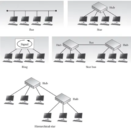
(see Figure 1-1), which depend on the type of cable used and the protocols running on the computers. The most common topologies are as follows:
• Bus A bus topology takes the form of a cable that runs from one computer to the next one in a daisy-chain fashion, much like a string of Christmas tree lights. All of the signals transmitted by the computers on the network travel along the bus in both directions to all of the other computers. The two ends of the bus must be terminated with electrical resistors that nullify the voltages reaching them so that the signals do not reflect in the other direction. The primary drawback of the bus topology is that, like the string of Christmas lights it resembles, a fault in the cable anywhere along its length splits the network in two and prevents systems on opposite sides of the break from communicating. In addition, the lack of
termination at either half can prevent computers that are still connected from communicating properly. As with Christmas lights, finding a single faulty
connection in a large bus network can be troublesome and time consuming. Most coaxial cable networks, such as the original Ethernet LANs, use a bus topology.
• Star (hub and spoke) A star topology uses a separate cable for each computer that runs to a central cabling nexus called a hub or concentrator. The hub propagates the signals entering through any one of its ports out through all of the other ports so that the signals transmitted by each computer reach all the other computers. Hubs also amplify the signals as they process them, enabling them to travel longer distances without degrading. A star network is more fault tolerant than a bus because a break in a cable affects only the device to which that cable is connected, not the entire network. Most of the networking protocols that call for twisted-pair cable, such as 10Base-T and 100Base-T Ethernet, use the star
topology.
• Star bus A star bus topology is one method for expanding the size of a LAN beyond a single star. In this topology, a number of star networks are joined
together using a separate bus cable segment to connect their hubs. Each computer can still communicate with any other computer on the network because each of the hubs transmits its incoming traffic out through the bus port as well as the other star ports. Designed to expand 10Base-T Ethernet networks, the star bus is rarely seen today because of the speed limitations of coaxial bus networks, which can function as a bottleneck that degrades the performance of faster star network technologies such as Fast Ethernet.
• Ring This topology is similar to a bus topology, except these topologies transmit in one direction only from station to station. A ring topology often uses separate physical ports and wires to send and receive data. A ring topology is functionally equivalent to a bus topology with the two ends connected so that signals travel from one computer to the next in an endless circular fashion.
The physical network is actually cabled using a star topology, and a special hub called a multistation access unit (MSAU) implements the logical ring by taking each incoming signal and transmitting it out through the next downstream port only (instead of through all of the other ports, like a star hub). Each computer, upon receiving an incoming signal, processes it (if necessary) and sends it right back to the hub for transmission to the next station on the ring. Because of this arrangement, systems that transmit signals onto the network must also remove the signals after they have traversed the entire ring. Networks configured in a ring topology can use several different types of cable. Token Ring networks, for
example, use twisted-pair cables, while FDDI networks use the ring topology with fiber-optic cable.
• Daisy chains These topologies are the simplest form as one device is
connected to another through serial ports. Think of a computer hooked to a printer and the printer, in turn, being hooked to a laptop.
Figure 1-1 Common cable topographies
The topologies discussed here are physical topologies, which differ from logical
topologies that are discussed in later chapters. Physical topologies refer to the placement of cables and other components of the network. Logical topologies refer to the flow of data on the network.
Media Access Control
When multiple computers are connected to the same baseband network medium, there must be a media access control (MAC) mechanism that arbitrates access to the network to prevent systems from transmitting data at the same time. A MAC mechanism is a
fundamental part of all local area networking protocols that use a shared network medium. The two most common MAC mechanisms are Carrier Sense Multiple Access with
Addressing
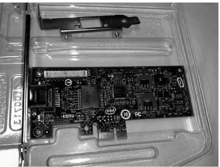
For systems on a shared network medium to communicate effectively, they must have some means of identifying each other, usually some form of numerical address. In most cases, the network interface card (NIC) installed into each computer has an address hard-coded into it at the factory, called its MAC address or hardware address, which uniquely identifies that card among all others. Every packet that each computer transmits over the network contains the address of the sending computer and the address of the system for which the packet is intended.
In addition to the MAC address, systems may have other addresses operating at other layers. For example, Transmission Control Protocol/Internet Protocol (TCP/IP) requires that each system be assigned a unique IP address in addition to the MAC address it already possesses. Systems use the various addresses for different types of communications. (See Chapter 3 for more information on MAC addressing and Chapter 13 for more information on IP addressing.)
Repeaters, Bridges, Switches, and Routers
LANs were originally designed to support only a relatively small number of computers— 30 for thin Ethernet networks and 100 for thick Ethernet—but the needs of businesses quickly outgrew these limitations. To support larger installations, engineers developed products that enabled administrators to connect two or more LANs into what is known as an internetwork, which is essentially a network of networks that enables the computers on one network to communicate with those on another. Don’t confuse the generic term
internetwork with the Internet. The Internet is an example of an extremely large
internetwork, but any installation that consists of two or more LANs connected is also an internetwork. This terminology is confusing because it is so often misused. Sometimes what users mean when they refer to a network is actually an internetwork, and at other times, what may seem to be an internetwork is actually a single LAN. Strictly speaking, a LAN or a network segment is a group of computers that share a network cable so that a broadcast message transmitted by one system reaches all of the other systems, even if that segment is actually composed of many pieces of cable. For example, on a typical 10Base-T Ethernet LAN, all of the computers are connected to a hub using individual lengths of cable. Regardless of that fact, this arrangement is still an example of a network segment or LAN. Individual LANs can be connected using several different types of devices, some of which simply extend the LAN while another creates an internetwork. These devices are as follows:
• Repeaters A repeater is a purely electrical device that extends the maximum distance a LAN cable can span by amplifying the signals passing through it. The hubs used on star networks are sometimes called multiport repeaters because they have signal amplification capabilities integrated into the unit. Stand-alone
repeaters are also available for use on coaxial networks to extend them over longer distances. Using a repeater to expand a network segment does not divide it into two LANs or create an internetwork.
with the ability to selectively filter packets based on their addresses. Packets that originate on one side of the bridge are propagated to the other side only if they are addressed to a system that exists there. Because bridges do not prevent broadcast messages from being propagated across the connected cable segments, they, too, do not create multiple LANs or transform a network into an internetwork.
• Switches Switches are revolutionary devices that in many cases eliminate the shared network medium entirely. A switch is essentially a multiport repeater, like a hub, except that instead of operating at a purely electrical level, the switch reads the destination address in each incoming packet and transmits it out only through the port to which the destination system is connected.
• Routers A router is a device that connects two LANs to form an
internetwork. Like a bridge, a router forwards only the traffic that is destined for the connected segment, but unlike repeaters and bridges, routers do not forward broadcast messages. Routers can also connect different types of networks (such as Ethernet and Token Ring), whereas bridges and repeaters can connect only
segments of the same type.
Wide Area Networks
Internetworking enables an organization to build a network infrastructure of almost unlimited size. In addition to connecting multiple LANs in the same building or campus, an internetwork can connect LANs at distant locations through the use of wide area network links. A WAN is a collection of LANs, some or all of which are connected using point-to-point links that span relatively long distances. A typical WAN connection consists of two routers, one at each LAN site, connected using a long-distance link such as a leased telephone line. Any computer on one of the LANs can communicate with the other LAN by directing its traffic to the local router, which relays it over the WAN link to the other site.
WAN links differ from LANs in that they do not use a shared network medium and they can span much longer distances. Because the link connects only two systems, there is no need for media access control or a shared network medium. An organization with offices located throughout the world can build an internetwork that provides users with instantaneous access to network resources at any location. The WAN links themselves can use technologies ranging from telephone lines to public data networks to satellite systems. Unlike a LAN, which is nearly always privately owned and operated, an outside service provider (such as a telephone company) is nearly always involved in a WAN connection because private organizations don’t usually own the technologies needed to carry signals over such long distances. Generally speaking, WAN connections can be slower and more expensive than LANs, and sometimes much more so. As a result, one of the goals of the network administrator is to maximize the efficiency of WAN traffic by eliminating unnecessary communications and choosing the best type of link for the application. See Chapter 7 for more information on WAN technologies.
• A MAN’s size is usually between that of a LAN and a WAN. Typically, it covers between 3 and 30 miles (5 to 50 km). A MAN can encompass several buildings, a company campus, or a small town.
• As with WANs, MANs are normally owned by a group or a network provider.
• MANs are often used as a way to provide shared access to one or more WANs.
Protocols and Standards
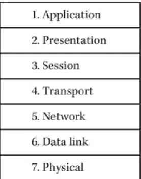
Communications between computers on a network are defined by protocols, standardized methods that the software programs on the computers have in common. These protocols define every part of the communications process, from the signals transmitted over network cables to the query languages that enable applications on different machines to exchange messages. Networked computers run a series of protocols, called a protocol stack, that spans from the application user interface at the top to the physical network interface at the bottom. The stack is traditionally split into seven layers. The Open Systems Interconnection (OSI) reference model defines the functions of each layer and how the layers work together to provide network communications. Chapter 2 covers the OSI reference model in detail.
Early networking products tended to be proprietary solutions created by a single manufacturer, but as time passed, interoperability became a greater priority, and
organizations were formed to develop and ratify networking protocol standards. Most of these bodies are responsible for large numbers of technical and manufacturing standards in many different disciplines. Today, most of the protocols in common use are standardized by these bodies, some of which are as follows:
• Institute of Electrical and Electronic Engineers (IEEE) A U.S.-based society responsible for the publication of the IEEE 802 working group, which includes the standards that define the protocols commonly known as Ethernet and Token Ring, as well as many others.
• International Organization for Standardization (ISO) A worldwide federation of standards bodies from more than 100 countries, responsible for the publication of the OSI reference model document.
• Internet Engineering Task Force (IETF) An ad hoc group of contributors and consultants who collaborate to develop and publish standards for Internet technologies, including the TCP/IP protocols.
Clients and Servers
computers when they request it. A client is the computer running a program that requests the service from a server.
For example, a LAN-based database application stores its data on a server, which stands by, waiting for clients to request information from it. Users at workstation computers run a database client program in which they generate queries that request specific information in the database and transmit those queries to the server. The server responds to the queries with the requested information and transmits it to the workstations, which format it for display to the users. In this case, the workstations are responsible for providing a user interface and translating the user input into a query language understood by the server. They are also responsible for taking the raw data from the server and
displaying it in a comprehensible form to the user. The server may have to service dozens or hundreds of clients, so it is still a powerful computer. By offloading some of the
application’s functions to the workstations, however, its processing burden is nowhere near what it would be on a mainframe system.
Operating Systems and Applications
Clients and servers are actually software components, although some people associate them with specific hardware elements. This confusion is because some network operating systems require that a computer be dedicated to the role of server and that other computers function solely as clients. This is a client-server operating system, as opposed to a peer-to-peer operating system, in which every computer can function as both a client and a server. The most basic client-server functionality provided by a network operating system (NOS) is the ability to share file system drives and printers, and this is what usually defines the client and server roles. At its core, a NOS makes services available to its network clients. The system can provide the following:
• Printer services, including managing devices, print jobs, who is using what asset, and what assets are not available to the network
• Managing user access to files and other resources, such as the Internet • System monitoring, including providing network security
• Making network administration utilities available to network administrators Apart from the internal functions of network operating systems, many LAN
applications and network services also operate using the client-server paradigm. Internet applications, such as the World Wide Web, consist of servers and clients, as do
administrative services such as the Domain Name System (DNS).
Most of today’s desktop operating systems are capable of providing some of the services traditionally ascribed to NOSs since many small-office/home-office (SOHO) LAN implementations take advantage of the fact. Understanding this may help clarify the distinction between LANs that are truly client-server, relying on network operating
2
The OSI Reference Model
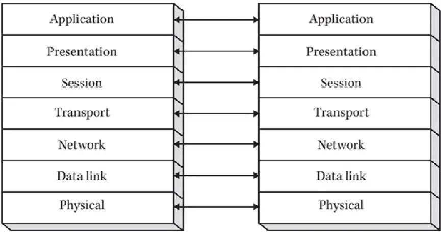
[image:40.595.229.368.268.444.2]Network communications take place on many levels and can be difficult to understand, even for the knowledgeable network administrator. The Open Systems Interconnection (OSI) reference model is a theoretical construction that separates network communications into seven distinct layers, as shown in Figure 2-1. Each computer on the network uses a series of protocols to perform the functions assigned to each layer. The layers collectively form what is known as the protocol stack or networking stack. At the top of the stack is the application that makes a request for a resource located elsewhere on the network, and at the bottom is the physical medium that actually connects the computers and forms the network, such as a cable.
Figure 2-1 The OSI reference model with its seven layers
The OSI reference model was developed in two separate projects by the International Organization for Standardization (ISO) and the Comité Consultatif International
Téléphonique et Télégraphique (Consultative Committee for International Telephone and Telegraphy, or CCITT), which is now known as the Telecommunications Standardization Sector of the International Telecommunications Union (ITU-T). Each of these two bodies developed its own seven-layer model, but the two projects were combined in 1983,
resulting in a document called “The Basic Reference Model for Open Systems
the physical layer.
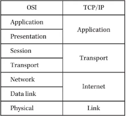
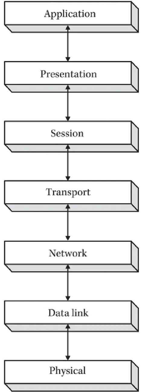
The primary reason why real protocol stacks differ from the OSI model is that many of the protocols used today (including Ethernet) were conceived before the OSI model documents were published. In fact, the TCP/IP protocols have their own layered model, which is similar to the OSI model in several ways but uses only four layers (see Figure 2-2). In addition, developers are usually more concerned with practical functionality than with conforming to a preexisting model. The seven-layer model was designed to separate the functions of the protocol stack in such a way as to make it possible for separate
[image:41.595.188.409.248.450.2]development teams to work on the individual layers, thus streamlining the development process. However, if a single protocol can easily provide the functions that are defined as belonging in separate layers of the model, why divide it into two separate protocols just for the sake of conformity?
Figure 2-2 The OSI reference model and the TCP/IP protocol stack
Communications Between the Layers
Networking is the process of sending messages from one place to another, and the protocol stack illustrated in the OSI model defines the basic components needed to transmit messages to their destinations. The communication process is complex because the applications that generate the messages have varying requirements. Some message exchanges consist of brief requests and replies that have to be exchanged as quickly as possible and with a minimum amount of overhead. Other network transactions, such as program file transfers, involve the transmission of larger amounts of data that must reach the destination in perfect condition, without alteration of a single bit. Still other
transmissions, such as streaming audio or video, consist of huge amounts of data that can survive the loss of an occasional bit, byte, or packet, but that must reach the destination in a timely manner.
The networking process also includes a number of conversions that ultimately take the application programming interface (API) calls generated by applications and transform them into electrical charges, pulses of light, or other types of signals that can be
package a letter by placing it in an envelope and writing an address on it, the networking protocols package the data generated by an application and address it to another computer on the network.
Data Encapsulation
To satisfy all of the requirements just described, the protocols operating at the various layers work together to supply a unified quality of service. Each layer provides a service to the layers directly above and below it. Outgoing traffic travels down through the stack to the network physical medium, acquiring the control information needed to make the trip to the destination system as it goes. This control information takes the form of headers (and in one case a footer) that surround the data received from the layer above, in a process called data encapsulation. The headers and footer are composed of individual fields that contain control information (necessary/required by the system to deliver) used to get the packet to its destination. In a sense, the headers and footer form the envelope that carries the message received from the layer above.
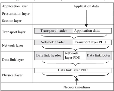
In a typical transaction, shown in Figure 2-3, an application layer protocol (which also includes presentation and session layer functions) generates a message that is passed down to a transport layer protocol. The protocol at the transport layer has its own packet
[image:42.595.80.515.417.764.2]structure, called a protocol data unit (PDU), which includes specialized header fields and a data field that carries the payload. In this case, the payload is the data received from the application layer protocol. By packaging the data in its own PDU, the transport layer encapsulates the application layer data and then passes it down to the next layer.
Figure 2-3 The application layer data is encapsulated for transmission by the protocols at the lower layers in the stack.
encapsulates it within its own PDU by adding a header and using the entire transport layer PDU (including the application layer data) as its payload. The same process occurs again when the network layer passes its PDU to the data link layer protocol, which adds a header and footer. To a data link layer protocol, the data within the frame is treated as payload only, just as postal employees have no idea what is inside the envelopes they process. The only system that reads the information in the payload is the computer possessing the destination address. That computer then either passes the network layer protocol data contained in the payload up through its protocol stack or uses that data to determine what the next destination of the packet should be. In the same way, the protocols operating at the other layers are conscious of their own header information but are unaware of what data is being carried in the payload.
Once it is encapsulated by the data link layer protocol, the completed packet (now called a frame) is then ready to be converted to the appropriate type of signal used by the network medium. Thus, the final packet, as transmitted over the network, consists of the original application layer data plus several headers applied by the protocols at the
succeeding layers, as shown in Figure 2-4.
Figure 2-4 An encapsulated frame, ready for transmission
NOTE
Each layer must translate data into its specific format before sending it
on. Therefore, each layer creates its own PDU to transmit to the next
layer. As each layer receives data, the PDU of the previous layer is read,
and a new PDU is created using that layer’s protocol. Remember, a PDU
is a complete message (or packet) that includes the protocol of the
sending layer. At the physical layer, you end up with a message that
consists of all the data that has been encapsulated with the headers and/or
footers from each of the previous layers.
Horizontal Communications
Figure 2-5 Each layer has logical connections with its counterpart in other systems.
The horizontal connections between the various layers are logical; there is no direct communication between them. The information included in each protocol header by the transmitting system is a message that is carried to the same protocol in the destination system.
Vertical Communications
The headers applied by the various protocols implement the specific functions carried out by those protocols. In addition to communicating horizontally with the same protocol in the other system, the header information enables each layer to communicate with the layers above and below it, as shown in Figure 2-6. For example, when a system receives a packet and passes it up through the protocol stack, the data link layer protocol header includes a field that identifies which network layer protocol the system should use to
Figure 2-6 Each layer in the OSI model communicates with the layer above and below it.
Encapsulation Terminology
generic term for the data unit at any stage in the process. Most data link layer protocols are said to work with frames because they include both a header and a footer that surround the data from the network layer protocol. The term frame refers to a PDU of variable size, depending on the amount of data enclosed. A data link layer protocol that uses PDUs of a uniform size, such as Asynchronous Transfer Mode (ATM), is said to deal in cells.
When transport layer data is encapsulated by a network layer protocol, such as the Internet Protocol (IP) or Internetwork Packet Exchange (IPX), the resulting PDU is called a datagram. During the course of its transmission, a datagram might be split into
fragments, each of which is sometimes incorrectly called a datagram. The terminology at the transport layer is more protocol-specific than at the lower layers. TCP/IP, for example, has two transport layer protocols. The first, called the User Datagram Protocol (UDP), also refers to the PDUs it creates as datagrams, although these are not synonymous with the datagrams produced at the network layer.
When the UDP protocol at the transport layer is encapsulated by the IP protocol at the network layer, the result is a datagram packaged within another datagram. The difference between UDP and the Transmission Control Protocol (TCP), which also operates at the transport layer, is that UDP datagrams are self-contained units that were designed to contain the entirety of the data generated by the application layer protocol. Therefore, UDP is traditionally used to transmit small amounts of data, while TCP, on the other hand, is used to transmit larger amounts of application layer data that usually do not fit into a single packet. As a result, each of the PDUs produced by the TCP protocol is called a
segment, and the collection of segments that carry the entirety of the application layer protocol data is called a sequence. The PDU produced by an application layer protocol is typically called a message. The session and presentation layers are usually not associated with individual protocols. Their functions are incorporated into other elements of the protocol stack, and they do not have their own headers or PDUs. All of these terms are frequently confused, and it is not surprising to see even authoritative documents use them incorrectly.
NOTE
While TCP is often used to transmit data packets today, there are
instances where UDP is suitable. For example, UDP is used when newer
data will replace previous data, such as in video streaming or gaming. As
another example of the need for newer data, consider weather information
that must be updated quickly during inclement weather. Also, since TCP
is a connection-oriented, streaming protocol, UDP is the preferred way to
multicast
(send data across a network to several users at the same time).
The following sections examine each of the seven layers of the OSI reference model in turn, the functions that are associated with each, and the protocols that are most
commonly used at those layers. As you proceed through this book, you will learn more about each of the individual protocols and their relationships to the other elements of the protocol stack.
The physical layer of the OSI model defines the actual medium that carries data from one computer to another. The two most common types of physical layer used in data
networking are copper-based electrical cable and fiber-optic cable. A number of wireless physical layer implementations use radio waves, infrared or laser light, microwaves, and other technologies. The physical layer includes the type of technology used to carry the data, the type of equipment used to implement that technology, the specifications of how the equipment should be installed, and the nature of the signals used to encode the data for transmission.
For example, for many years, the most popular physical layer standards used for local area networking was 10Base-T Ethernet. Ethernet is primarily thought of as a data link layer protocol. However, as with most protocols functioning at the data link layer, Ethernet includes specific physical layer implementations, and the standards for the protocol define the elements of the physical layer as well. 10Base-T referred to the type of cable used to form a particular type of Ethernet network. The Ethernet standard defined 10Base-T as an unshielded twisted-pair cable (UTP) containing four pairs of copper wires enclosed in a single sheath. Today, Ethernet is found at much faster speeds such as 100Base-T running at 100 megabits per second, or 1000Base-T, which runs at 1 gigabit per second.
NOTE
The physical layer uses the binary data supplied by the data link layer
protocol to encode the data into pulses of light, electrical voltages, or
other impulses suitable for transmission over the network medium.
However, the construction of the cable itself is not the only physical layer element involved. The standards used to build an Ethernet network also define how to install the cable, including maximum segment lengths and distances from power sources. The standards specify what kind of connectors you use to join the cable, the type of network interface card (NIC) to install in the computer, and the type of hub you use to join the computers into a network topology. Finally, the standard specifies how the NIC should encode the data generated by the computer into electrical impulses that can be transmitted over the cable.
Thus, you can see that the physical layer encompasses much more than a type of cable. However, you generally don’t have to know the details about every element of the physical layer standard. When you buy Ethernet NICs, cables, and hubs, they are already constructed to the Ethernet specifications and designed to use the proper signaling scheme. Installing the equipment, however, can be more complicated.
Physical Layer Specifications
permitted on a network. These guidelines are common knowledge to Ethernet network administrators, but these rules alone are not sufficient to perform a large cable installation. In addition, there are local building codes to consider, which might have a great effect on a cable installation. For these reasons, large physical layer installations should, in most cases, be performed by professionals who are familiar with all of the standards that apply to the particular technology involved. See Chapter 4 for more information on network cabling and cable installation.
NOTE
The latest revision to the IEEE 802.3 “Standard for Ethernet” was
published in September 2012. It was amended to “address new markets,
bandwidth speeds, and media types” according to the IEEE web site at
http://standards.ieee.org
.
NOTE
Collision detection is when one device (or node) on a network
determines that data has “collided.” This is similar to two people coming
through a revolving door at the same time, but in that case, one person
can see the other person and stops. If one node hears a distorted version
of its own transmission, that node understands that a collision has
occurred and, just like the person who stops to allow the other to go
through the revolving door, that node will stop the transmission and wait
for silence on the network to send its data.
Physical Layer Signaling
The primary operative component of a physical layer installation is the transceiver found in NICs, repeating hubs, and other devices. The transceiver, as the name implies, is
responsible for transmitting and receiving signals over the network medium. On networks using copper cable, the transceiver is an electrical device that takes the binary data it receives from the data link layer protocol and converts it into signals of various voltages. Unlike all of the other layers in the protocol stack, the physical layer is not concerned in any way with the meaning of the data being transmitted. The transceiver simply converts zeros and ones into voltages, pulses of light, radio waves, or some other type of signal, but it is completely oblivious to packets, frames, addresses, and even the system receiving the signal.
The signals generated by a transceiver can be either analog or digital. Most data networks use digital signals, but some of the wireless technologies use analog radio transmissions to carry data. Analog signals transition between two values gradually, forming the sine wave pattern shown in Figure 2-7, while digital value transitions are immediate and absolute. The values of an analog signal can be determined by variations in amplitude, frequency, phase, or a combination of these elements, as in amplitude
Figure 2-7 Analog signals form wave patterns.
[image:49.595.78.521.416.626.2]The use of digital signals is much more common in data networking, however. All of the standard copper and fiber-optic media use various forms of digital signaling. The signaling scheme is determined by the data link layer protocol being used. All Ethernet networks, for example, use the Manchester encoding scheme, whether they are running over twisted-pair, coaxial, or fiber-optic cable. Digital signals transition between values almost instantaneously, producing the square wave shown in Figure 2-8. Depending on the network medium, the values can represent electrical voltages, the presence or absence of a beam of light, or any other appropriate attribute of the medium. In most cases, the signal is produced with transitions between a positive voltage and a negative voltage, although some use a zero value as well. Given a stable voltage within circuit specifications, the transitions create the signal.
Figure 2-8 Polar encoding
NOTE
Digital signals are susceptible to voltage degradation; a digital circuit
designed for a 5-volt application will most likely behave erroneously if
voltage attenuation results in signals of 3 volts, meaning the circuit will
now not be able to distinguish whether there was a transition event since
the signal is below the design threshold.
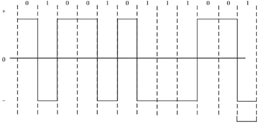
the signal is broken up into units of time called cells, and the voltage of each cell denotes its binary value. A positive voltage is a zero, and a negative voltage is a one. This
signaling code would seem to be a simple and logical method for transmitting binary information, but it has one crucial flaw, and that is timing. When the binary code consists of two or more consecutive zeros or ones, there is no voltage transition for the duration of two or more cells. Unless the two communicating systems have clocks that are precisely synchronized, it is impossible to tell for certain whether a voltage that remains continuous for a period of time represents two, three, or more cells with the same value. Remember that these communications occur at incredibly high rates of speed, so the timing intervals involved are extremely small.
Some systems can use this type of signal because they have an external timing signal that keeps the communicating systems synchronized. However, many data networks run over a baseband medium that permits the transmission of only one signal at a time. As a result, these networks use a different type of signaling scheme, one that is self-timing. In other words, the data signal itself contains a timing signal that enables the receiving system to correctly interpret the values and convert them into binary data.
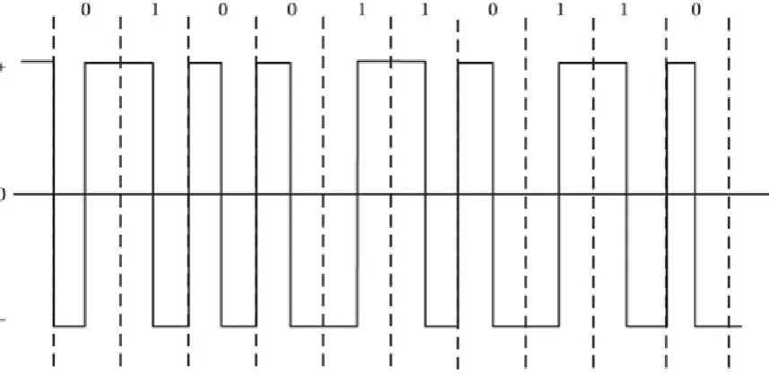
The Manchester encoding scheme used on Ethernet networks is a self-timing signal by virtue of the fact that every cell has a value transition at its midpoint. This delineates the boundaries of the cells to the receiving system. The binary values are specified by the direction of the value transition; a positive-to-negative transition indicates a value of zero, and a negative-to-positive transition indicates a value of one (see Figure 2-9). The value transitions at the beginnings of the cells have no function other than to set the voltage to the appropriate value for the midcell transition.
Figure 2-9 The Manchester encoding scheme
Figure 2-10 The Differential Manchester encoding scheme
The Data Link Layer
The data link layer protocol provides the interface between the physical network and the protocol stack on the computer. A data link layer protocol typically consists of three elements:
• The format for the frame that encapsulates the network layer protocol data • The mechanism that regulates access to the shared network medium
• The guidelines used to construct the network’s physical layer
The header and footer applied to the network layer protocol data by the data link layer protocol are the outermost on the packet as it is transmitted across the network. This frame is, in essence, the envelope that carries the packet to its next destination and, therefore, provides the basic addressing information needed to get it there. In addition, data link layer protocols usually include an error-detection facility and an indicator that specifies the network layer protocol that the receiving system should use to process the data included in the packet.
On most LANs, multiple systems access a single shared baseband network medium. This means that only one computer can transmit data at any one time. If two or more systems transmit simultaneously, a collision occurs, and the data is lost. The data link layer protocol is responsible for controlling access to the shared medium and preventing an excess of collisions.
When speaking of the data link layer, the terms protocol and topology are often
computers are actually cabled using a star topology. This confusion is understandable since most data link layer protocols include elements of the physical layer in their
specifications. It is necessary for the data link layer protocol to be intimately related to the physical layer because media access control mechanisms are highly dependent on the size of the frames being transmitted and the lengths of the cable segments.
Addressing
The data link layer protocol header contains the address of the computer sending the packet and the computer that is to receive it. The addresses used at this layer are the
hardware (or MAC) addresses that in most cases are hard-coded into the network interface of each computer and router by the manufacturer. On Ethernet and Token Ring networks, the addresses are 6 bytes long, the first 3 bytes of which are assigned to the manufacturer by the Institute of Electrical and Electronic Engineers (IEEE), and the second 3 bytes of which are assigned by the manufacturer. Some older protocols used addresses assigned by the network administrator, but the factory-assigned addresses are more efficient, insofar as they ensure that no duplication can occur.
The data link layer protocol does the following: • Provides packet addressing services
• Packages the network layer data for transmission • Arbitrates network access
• Checks transmitted packets for errors
Data link layer protocols are not concerned with the delivery of the packet to its ultimate destination, unless that destination is on the same LAN as the source. When a packet passes through several networks on the way to its destination, the data link layer protocol is responsible only for getting the packet to the router on the local network that provides access to the next network on its journey. Thus, the destination address in a data link layer protocol header always references a device on the local network, even if the ultimate destination of the message is a computer on a network miles away.
The data link layer protocols used on LANs rely on a shared network medium. Every packet is transmitted to all of the computers on the network segment, and only the system with the address specified as the destination reads the packet into its memory buffers and processes it.