Journal of Chemical and Pharmaceutical Research, 2014, 6(3):245-250
Research Article
CODEN(USA) : JCPRC5
ISSN : 0975-7384
245
Simulation and optimization of hydraulic excavator’s working device based
on MATLAB
1,2
Gui Ju-Zhang,
2Cai Yuan-Xiao*,
1Qing-Tan and
3You Yu-Mo
1
College of Mechanical and Electrical Engineering, Central South University, Changsha, Hunan, China
2Department of Mechanical and Energy Engineering, Shaoyang University, Shaoyang, Hunan, China
3
Hydraulic Technology Institute of Guangxi Yuchai Heavy Industry Co., LTD, Yulin, Guangxi, China
_____________________________________________________________________________________________ABSTRACT
The kinematic and dynamic analysis of hydraulic excavator’s working device was carried out in this paper by using the De-navit-Hartenberg homogeneous transformed matrix. And then we worked out the optimization results of comprehensive characteristics for kinematic and dynamics based on using the max digging power as the aim of optimization. It established the theoretic foundation for further study in order to realize the hydraulic excavator’s automatic control. Finally take the type of YC225LC-8 hydraulic backhoe excavator for example, simulation and optimization analysis of it’s comprehensive characteristics. The research results showed that the method of C + + Builder and MATLAB mixed programming is make full use of MATLAB powerful scientific computing, as well as C + + Builder powerful interface development function. And the program development process is simple, high process efficiency and has reliable optimization results. It can find solid theoretical calculation foundation for further research on mining automatic. And it own the value of engineering application.
Keywords:hydraulic excavator; working device; boom; MATLAB
_____________________________________________________________________________________________
INTRODUCTION
For its high efficiency and multifunction, hydraulic excavator is widely used in mines, road and railway building, water conservancy, civil and military construction and hazardous waste cleanup areas.In the design process of hydraulic excavator, the working device’s design is one of the most important contexts. Especially, the boom is the main load-bearing component in an excavator, its stiffness directly influence the working efficiency and service life of an excavator. [1]
In the traditional strength calculation of hydraulic excavator’s boom, we usually use the material mechanics method, the boom is assumed to be a beam, and then calculate the bending strength of various cross sections. However, because the actual boom structure is far different from the ideal beam structure and stress is very complex, so that the errors will be apparentlylargeaccording to beam assumption and can not reflect the deformation and stress of the whole structuredistribution.[2] In practice, the excavator produced by traditional design method is often failurewhen in use.
THE KINEMATIC AND DYNAMICANALYSIS OF HYDRAULIC EXCAVATOR’S WORKING DEVICE.
The kinematic analysis of robotized motion for hydraulic excavator: As shown in Fig.1. The operation of the hydraulic excavator’s working equipment is very similar to the stock-taking robot [3]. It’s a kind of multi-rod system with four degrees of freedomrespectively as:the revolute pair of rotary device around substrate base, the revolute pair of boom relative to rotarydevice, therevolute pair of bucket rod around the end of the boom and the revolute pair of bucket around the end of bucket rod.
For hydraulic excavator robot,given the base coordinate system
L
0(
x
0,
y
0,
z
0)
and rotating coordinatesystem
L
i(
x
i,
y
i,
z
i)
(i = 1, 2, 3), it uses theDenavit-Hartenberghomogeneous.Fig.1: The coordinate system of working equipment robotics
homogeneous transformation matrix to carry out kinematic analysis for excavator . The bars
l
i and bracketsL
ican be considered as firstly rotate degrees
i1 aroundX
i1 axis relative to theL
i1 denoted as the Rot (X
i1,1
i
); then translatea
i1 alongX
i1 axis denoted as Trans (X
i1,a
i1); and then translated
i alongZ
i axis denoted by Trans (Z
i,d
i); and finally rotate degrees
i aroundZ
i axis denoted as the Rot (Z
i,
i); Thus the homogeneous transformationL
i relative toL
i1 can be considered as: rotation (
i1) — translation(a
i1)— translation (d
i) — rotation (
i), whose transformation matrix is:)
θ
,
)Rot(Z
d
,
)Trans(Z
a
,
)Trans(X
α
,
Rot(X
A
i1 i1 i1 i1 i1 i i i ii
=
1 0
0 0
cos sin
0
sin cos
sin cos
cos sin
cos sin
sin sin cos cos
i i
i
i i i i i
i i
i i i i i i i
d a a
(1)
Where, the four scalars
ia
id
i and
i are the parameters of i-th link. For rotating joints,
i is corresponding to the joint variables
i, and for moving the joint,d
i is alignment at the joint variable
i.The kinematic equations of mechanism are described by the transform matrix 0
i
A
. In order to easily control the parameters as position, velocity and acceleration for boom, bucket rod as well as bucket.A
i0 can be represented as the function which only conclude variables of
1,
2,
3 and
4:)
(
)
(
)
(
)
,
,
,
(
12 1 2 1 0 1 2
1 0
i i i i
i
A
A
A
A
(
i
=1, 2, 3, 4) (2)and as
p
0 in base coordinate systemL
0 . Both of them are linked by the transformation matrix, i.e.)
4
,
3
,
2
,
1
(
0 0
A
p
i
p
ii . In this case, the velocity of the point is:
i i j j j i t p
p
A
d
d
1 0 0
(
i
=1, 2, 3, 4) (3)Acceleration is:
i i j j j i t
p
A
d
p
d
1 2
0 2 2 0 2
(
i
=1, 2, 3, 4) (4)The calculation of digging force (driving force) :The digging force
d
mof a tiny mass concentrated on a point for mechanism is:m i i
j j j
i m
t
i
p
d
A
d
d
p
d
dF
1 2
0 2 2 0 2
(
i
=1, 2, 3, 4) (5)Digging force
F
i of the entire mechanismi
is the integration to tiny mass digging forcei F
d
: m i i j j j i m t ii
p
d
A
d
d
p
d
dF
F
1 2
0 2 2 0 2
(i
=1, 2, 3, 4) (6)Digging force is one of the important indicators to measure the performance of the hydraulic excavator. When design digging force, the working equipment should ensure structural optimization and meet strength requirement under the specified rated load [4], at the same time, it also must be ensure the other two cylinders can be interlocked when independently operated any hydraulic cylinder and developed a maximum thrust forceunder the setting pressure of system, thereby it can achieve maximum digging force and avoid slipping of machine topples [5]. The whole machine digging force can be calculated and measured by bucket hydraulic cylinder and hydraulic cylinders.And the theoretical maximum digging force can be obtained by optimization method.
The maximum digging force of bucket hydraulic cylinder is:
3 4 2 3 4 3 3 3 4 2 4 0 4 2 3 2 0 2 3 4 3 4) ( A a l m A m d p d m a m MaxF t (7)
The maximum digging force of bucket rod hydraulic cylinder is:
3 4 2 2 4 2 2 2 3 4 3 2 3 0 3 2 2 3 4 2 0 2 2 3 4 3 2 4 3, )
( A a l m A A m A d p d m A a m MaxF t
(8)When using the bucket cylinder or the bucket rod cylinder digging, the machine’s theoretical maximum digging force is influenced by several forces, such as the interlocking force W1of boom cylinder, the interlocking force W2of
bucket rod hydraulic cylinder, the interlocking force W3of bucket cylinder,the maximum digging force
W4overcomed by ground condition’s attached limitations, and the maximum digging force W5overcomed by the
whole machine’s steady state. The actual digging force of which is the smallest one from W1, W2, W3, W4, W5,
INTEGRATED OPTIMIZATION OF MOTION AND POWER
Establish the mathematical modelof the performance parameters:For the optimization problem of the hydraulic excavator’s working equipment, they often want to havemaximum digging force of the bucket cylinder, maximum digging force of bucket rod cylinder and other indicators which can reach the optimal value. They have more than one objective functions, and this problem is known as a multi-objective optimization problem.
Design variables:
x
x
(
l
30,
Z
C,
l
1,
l
2,
l
3,
2,
3,
4)
(9)which
Z
Cis the z-axis coordinate of movable . Mathematical model of optimization problems:
ni
i
i
x
ZG
F
x
F
1
)
)
(
(
)
(
min
x
R
n0
)
(
x
G
ii
1
,
,
m
e0
)
(
x
G
ii
m
e
1
,
,
m
,x
i
x
x
n (10)In the formula,
F
(
x
)
is the objective function vector,F
i(
x
)
are sub-objective functions,ZG
i and are sub-objective weighted coefficients.There are many solutions of multi-objective planning problems: weight-sum method,
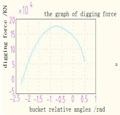
constraint method, goal attainment method and so on.The performance parameters of movement and power integrated optimization methods and proceduresUsing C++ Builder to develop the interface of application program and using MATLAB to write optimization model for solving subroutine, then achieving mixed programming of MATLAB engine and C++ Builder by invoking MATLAB engine functions. On the basis of the established specific optimization model, they regard optimization toolbox function as a "black box" [7]. According to the requirements of the chosen optimization tool function, they analyze the constraints, list the files and corresponding constraints of system matrix, call optimization toolbox, then they can get reliable optimization results simply and rapidly. Look YC225-LC-8 hydraulic excavator as an example, part of the optimization program is as follows:
%flopt0.1m
Function f=flopt01 (x)
);
14000
11283
2
8957
3
500
(
X
X
X
f
[X, fval] =fminbnd (‘flopt01’, -2.2959, 0.5381)The results:
X=
-0.6671 fval=
-1.78009e+005
The results showed that, when
4
0
.
6671
, the maximum digging force is 17800kN.Fig.2: Excavator digging force curves before and after optimization
Table 1: Optimization of parameters before and after contrast table
working condition θ2 θ3 θ4 maximum digging
force/KN
note
before the
optimization bucket hydraulic cylindermotion arbitrary arbitrary -0.6671 178010 with the designparameters
bucket rod hydraulic
cylinder motion
arbitrary -0.527 0.5381
(transformation)
186410 θ4
where nonsense
the optimized Bucket hydraulic cylinder
motion arbitrary arbitrary -0.567 191010 Increased by 7.5%
Bucket rod hydraulic
cylinder motion
arbitrary -0.563 0.5381
(transformation)
196710 θ4
where nonsense
CONCLUSION
According to the results of the YC225LC-8 hydraulic excavator optimization analysis, its original design parameters need to further improve. The optimization results show that compared with foreign advanced models, the main design of the excavator working device amended as follows: using a long boom, boom hinge point distance of 5700mm; boom bending angle of
112
.
5
0 (the original is131
0 ). The aim is to expand the job range of the excavator above ground; using standard stick to expand the operating range following the excavator ground; doing research and analysis on wording condition on the basis of ensuring the carrying capacity of the institution of a variety of conditions to reduce the geometry of the plateand reinforce sectional view of the main force, thereby reduce the weight of the work apparatus. After calculated, the working device is lighter than the original model by 11.7%; it can increase the size of the apparatus on the basis of the same machine heavy grade to expand the scope of the job.The method of C + + Builder and MATLAB mixed programming is make full use of MATLAB powerful scientific computing, as well as C + + Builder powerful interface development function. And the program development process is simple, high process efficiency and has reliable optimization results. It can find solid theoretical calculation foundation for further research on mining automatic. And it has the value of engineering application.
Acknowledgement
The authors would like to thank for the support by scientific research project of Education Department of Hunan province under the grant 12C0862. The authors also thank for the support by Natural Science Foundation of China under the Grant 51274252.
REFERENCES
[1] Tian L., Zhang W. and Wang H.B.,2011. Study on finite element method of power working device of hydraulic excavator. International Conference on Electronic & Mechanical Engineering and Information Technology, pp: 4216-4219.
[image:5.595.65.546.312.411.2]kinematics and dynamics. Construction Machinery. 80-82.
[3] Wu G.Y.etal.,1998. Robot engineering introduction. Harbin Institute of Technology press. [4] He Q.H., Hao P., Zhang D.Q.,2008.J.Cent.South Univ.Techn01. 15: 382-386.
[5] Yu G.F. et al.,2003.Transactions of the Chinese Society of Agricultrual Machinery.34:94-96.