MOHD FIRDAUS BIN ABAS
A project report submitted in partial
fulfillment of the requirement for the award of the Degree of Master of Mechanical Engineering
Faculty of Mechanical and Manufacturing Engineering Universiti Tun Hussein Onn Malaysia
ABSTRACT
CONTENTS
TITLE
DECLARATION
DEDICATION
ACKNOWLEDGEMENT
ABSTRACT
CONTENTS
LIST OF TABLES
LIST OF FIGURES
LIST OF SYMBOLS AND ABBREVIATIONS
LIST OF APPENDICES
CHAPTER 1 INTRODUCTION
1.1 Introduction
1.2 Background study
i
ii
iii
iv
v
vii
xii
xiii
xviii
xix
1
1
1.5 Significance of study
1.6 Scopeofstudy
CHAPTER 2 LITERATURE REVIEW
2.1 Introduction
2.2 Software variation
2.2.1 ANSYSbackgroundstudy
2.2.1.1 Claims
2.2.2 ABAQUSbackgroundstudy
2.2.2.1 Claims
2.2.3 STAR-CD background study
2.2.3.1 Claims
2.3 Software of interest
2.4 Meshing variation
2.5 Meshing of interest
CHAPTER 3 METHODOLOGY
3.1 Introduction
3.2 Methodology flowchart
3.3 Significant of ANSYS
3.3.1 Advantages of ANSY S
3.3.2 The governing equations
3.4 Availability
3.5 Technical drawings
3.5.1 Design modelling
3.5.2 Meshing
3.5.3 Simulation setup
CHAPTER 4 RESULTS AND DISCUSSION
4.1 Introduction
4.2 NACA 00 12 validation
4.3 Validation analysis
4.4 Simulation results
4.4.4 Case 4: +lo0 deflection angle
4.4.5 Case 5: +5" deflection angle
4.4.6 Case 6: 0" deflection angle
4.4.7 Case 7: -5" deflection angle
4.4.8 Case 8: -10" deflection angle
4.4.9 Case 9: -15" deflection angle
4.4.10 Case 10: -20" deflection angle
4.4.1 1 Case 1 1 : -28" deflection angle
4.5 Discussion
4.6 Frequently asked questions
CHAPTER 5 CONCLUSION AND RECOMMENDATION
5.1 Conclusion
REFERENCES
LIST OF TABLES
Horizontal tail's basic dimensions
Meshing setup Simulation setup Mesh type comparison Result data comparison
Cases considered for simulation
+28" deflection angle simulation result data
+20° deflection angle simulation result data
+15" deflection angle simulation result data
+lo0 deflection angle simulation result data
+5" deflection angle simulation result data
0" deflection angle simulation result data
-5" deflection angle simulation result data
- 10" deflection angle simulation result data
-1 5" deflection angle simulation result data
-20" deflection angle simulation result data
-28" deflection angle simulation result data
Summarized stall's angle of attack
Coordinate comparison Velocity contour descriptions
LIST OF FIGURES
Features available in ANSYS Mesh parameter changes
Automated hex meshing using MultiZone mdsh method
Automated structural meshing with well-shaped quadratic tetrahedral elements
DLR F6 wing-fuselage parameterization Comparison of before and after optimization
Surface mesh for generic transport aircraft with close up of the pylon
Common aircraft types
Representation of whole configuration geometry Ranger 2000 models
Mesh generation for sumo geometry
Details of surface mesh on Ranger 2000 T-tail
Self-adapted grid
Automated mesh refinement and isobands of Mach number of inviscid flow
Patched grid
Validation of the Chimera overlapping grid
technique
Hybrid Cartesian grid after 2 adaption steps and isobands of pressure of inviscid flow
LIST OF SYMBOLS AND ABBREVIATIONS
m
-
C -
Cl -
C d
-
c*
-
A
-
STOL
UTHM
Angle of attack Density
Gravity = 9.8 1 m/s Velocity
Pressure Time Stress
Dynamic viscosity Other body forces Lift force
Drag force Pitching moment Chord length Lift coefficient
Drag coefficient Moment coefficient Reference area
-
Short Take-Off and Landingxix
LIST OF APPENDICES
APPENDIX TITLE
+28" Simulation Results
+20° Simulation Results
+15" Simulation Results
+
10" Simulation Results+5" Simulation Results
0" Simulation Results
-5" Simulation Results
-
1 0" Simulation Results-1 5" Simulation Results
-20" Simulation Results
-28" Simulation Results
Simulation Corrections
CHAPTER 1
INTRODUCTION
1.1 Introduction
In the history of long distance travelling, transportation is an important aspect which contributes to the comfort, luxury, and smooth sailing with sufficient speed to deliver anyone to their respective destination as fast as possible. As transportation evolves, the theory of friction reduction has elevated vehicle such as a simple automobile, into an aircraft, a masterpiece that flew through the vast sky, realizing one of human’s wildest dreams; to fly freely like a bird.
The airplane, originally an ingenious invention by the Wright brothers, has pushed every aspect of engineering brilliance to the very limits of technology. The design and manufacturing process takes precise measurement and coordination. Every individual part has its own critical role and works simultaneously together with all the other parts to climb, dive, turn, and even roll this hefty metal bird in the air. The crucial elements which make all of the manoeuvres possible for an aircraft are aerodynamics and how we utilize it, or in other words, “direct” it, according to the pilot’s needs.
2
manufacturing process of each part must undergo extensive quality control tests to ensure all part’s specifications are in line with standard requirements.
A horizontal tail is a small lifting surface which is located on the empennage (the rear part) of an aircraft. Varying from its other counterpart, the main lifting surfaces, which are the wings, serve mainly for providing a large amount of lift to maintain and manoeuvre the aircraft in mid-air while the horizontal tail serves for maintaining the equilibrium, stability, and control over the aircraft.
Today, technology development has made computational analysis and numerical prediction possible for simulating airflow over a horizontal tail. To determine the air flow characteristics for a set of stabilizer and elevator using
simulation software, it is a priority to understand how fluid flows and how to model a rigid body (stabiliser and elevator) before simulating the airflow over it.
1.2 Background study
Aerofoil, a specific geometry strongly related to the aeronautical engineering, is a structure with curved surfaces designed to give the most favourable ratio of lift to drag in flight. It is used as the basic form of, for instance, the wings, fins, and horizontal stabilizers of most aircrafts. Attempting to grasp the engineering wonders behind everything that makes a bulky metal structure into an aircraft is an act of jack-of-all-trades. However, the basic engineering theory for all the major parts of an aircraft are all the same, either in designing the wings, fins or stabilizers, since it will all refer to the same crucial principal; the effectiveness of the aerofoil shape.
Focusing at the rear of a fuselage (the tail section), most aircraft will have a horizontal stabilizer and an elevator. The stabilizer is a fixed wing section whose job is to provide stability for the aircraft, so that it will keep flying straight. The
horizontal stabilizer prevents unnecessary pitching (up and down movement) motion of the aircraft nose. The elevator is the small moving section at the rear of the
stabilizer that is attached to the fixed sections by hinges.
angle of attack of the wing. Changing the inclination of the wing to the local flight path will change the amount of lift which the wing generates. This, in turn, causes the aircraft to climb or dive. During “take-off”, the elevators are used to bring the nose of the aircraft up to begin the “climb-out”. During a banked turn, elevator inputs can increase the lift and cause a tighter turn.
That is why the performance of stabilizers, paired with their respective elevators, is extremely important in piloting an aircraft, which determines the manoeuvrability of the aircraft itself.
The amount of drag or lift generated by the interactions between the fluid flow and stabilizer-elevator are commonly measured via their respective coefficients, which are dimensionless quantities that are used to quantify drag (reaction force in the opposite direction of any given airflow velocity) and lift (reaction force in the normal direction of any given airflow velocity), respectively, of an object in a fluid environment such as air or water. The nomenclature CD and CL are being used in their respective drag and lift equations, which directly affect the final amount of drag and lift force acted on an aerodynamic body (i.e. higher CD and CL will indicate higher drag and lift force, and vice-versa). These coefficients will simplify the calculation of airfoils with identical surface profile as they are dimensionless and applicable to any chord length.
1.3 Problem statement
The aircraft horizontal tail that consists of stabilizer-elevator is the subject of interest in this study. The elevator works by changing the effective shape of the aerofoil of the horizontal tail. Changing its angle of deflection would affect the amount of lift generated. Lift force increases with greater downward deflection and vice-versa.
4
This work simulates and concludes at what angle of deflection the airflow characteristics will be optimized at its respective angle of attack.
1.4 Objectives
The objectives of this study are:
1. To determine air flow characteristics for a set of stabilizer-elevator using simulation software.
2. To determine the optimum deflection angle of the elevator with its respective Reynolds number, Re and Mach number, Ma.
1.5 Significance of study
It is relevant for this simulation to be applied in the design and manufacturing industries as it does not only help to determine the optimum deflection angle that positively affects the horizontal tail, but also reduces the production cost by simulating the outcome of a design first and making any modification necessary during this stage, before manufacturing process.
The scopes of this study are as follow:
Study of fluid properties in Advanced Fluid Dynamics.
Model of the rigid body (stabilizer and elevator).
Simulation of the air flow over the rigid body.
Discretization of the governing equations.
6
CHAPTER 2
LITERATURE REVIEW
2.1 Introduction
There are many before this whose have been researching on the air flow properties and aerodynamic characteristics of the wings and horizontal stabilizers of an aircraft and suggested on the improvement of the effectiveness of its aerofoil shape. Those researches in the past are were well known for its validation superiority because of their method using experimental analysis, but such method consumes a lot of time, cost, and effort to build and set up the facility and equipments; the obvious facility would be the wind tunnel. Moreover, the samples of models must be made
beforehand with conventional method, which will consume more time and material cost, which will then be most likely be done repetitively until the exact or desired shape and result has been acquired. Theoretically, more failed experiments will result in more waste of materials, which will then be translated to cost-wise lost.
As technology advances, a lot of computer-base aids have been developed to help engineers all around the world, from every aspect of engineering field, from
designing initial components for an electronic device to calculating and analyzing a structure accurately before deciding whether the project is safe for public use or otherwise. Here are some of the well-known software which has been rated “above-average-performance” by most engineers in aiding with projects associated with component designing and overall analysis capabilities. Their background study and what the software claims it can achieve are shown as below.
2.2.1 ANSYS background study
As reviewed by most new-age engineers, ANSYS is a newly develop, general purpose software, used to simulate interactions of all disciplines of physics,
structural, vibration, fluid dynamics, heat transfer, and electromagnetic for engineers. ANSYS enables the user to simulate tests or working conditions, which lets the user to test his/her designed model in virtual environment before manufacturing an actual prototype of the model. Determining and improving weak points, computing life and foreseeing probable problems are also possible with 3-dimensional simulations in virtual environment.
8
Figure 2.1: Features available in ANSYS [22]
As previously mentioned; ANSYS can import CAD data and also enables user to build a geometry with its processing abilities. Similarly in the same pre-processor, finite element model or also known as “mesh” which is required for computation is generated. After defining loadings and carrying out analyses, results can be viewed as numerical and graphical. Furthermore, ANSYS can carry out advanced engineering analyses quickly, safely, and practically by its variety of contact algorithms, time-base loading features, and non-linear material models.
Another important feature that ANSYS has to offer, which no other software within the same genre could, is its Workbench platform. As defined by FIGES Engineering, ANSYS Workbench is a platform which integrates simulation
In order to study and determine the air flow characteristics and aerodynamic properties surrounding the stabilizer and elevator, ANSYS also provide solution which uses Fluid Dynamics approaches, which is available as one of the features in its Workbench platform [22].
ANSYS claims that:
Its Fluid Dynamics solutions allow user to confidently predict the impact of any fluid behaviour on the user’s product.
Unparalleled fluid flow analysis capabilities.
Provide all the tools needed to design and optimize new equipment and to troubleshoot already existing installations.
Gives the user an insight into his/her product’s performance, single- or multi-phase, isothermal or reacting, compressible or incompressible.
Well validated ANSYS Fluent and ANSYS CFX are available from its Workbench platform.
Provide robust and high-speed solvers with advanced modelling capabilities.
The technology is highly scalable, which provides efficient parallel calculations from a few to thousands of processing cores.
Allows user to perform advanced quantitative analysis or create high-quality visualizations and animations with its Fluent-CFX combination, full-featured, ANSYS CFD-Post fluid flow post-processing tool.
ANSYS Workbench delivers high productivity and easy to use workflows.
Integrates pre-processing, simulation, and post-processing of fluid workflow needs.
Integrates fluid structure interaction studies and electromagnetic/fluid coupling of multi-physics needs.
10
2.2.2 ABAQUS background study
As one of many ANSYS adversaries, ABAQUS is a general purpose FEA package used to simulate the response of structures and solid bodies to loads, impacts, and thermal stress, and to visualize the results of simulations. As claimed by Indiana University’s knowledge base, ABAQUS software suite delivers accurate, robust, high-performance solutions for challenging non-linear problems, large scale linear dynamics applications, and routine design simulations.
Reviewing from ABAQUS’s respective vendor’s overview on its official website, Dassault Systèmes Simulia Corporation stated that product simulation is often being performed by engineering groups using niche simulation tools from different vendors to simulate various design attributes. The use of multiple vendor software products creates inefficiencies and increases costs. Therefore, in order to counter such problems, Simulia has decided to deliver a scalable suite of unified analysis products that allow all users, regardless of their simulation expertise or domain focus, to collaborate and seamlessly share simulation data and approved methods without loss of information fidelity. Thus, ABAQUS was introduced to the commercializing world of academic and industrial engineering.
As the vendor further explained, Simulia claims that the ABAQUS Unified FEA product suite offers powerful and complete solutions for both routine and sophisticated engineering problems, covering a vast spectrum of industrial
applications. For example, in the automotive industry, engineering work groups are able to consider full vehicle loads, dynamic vibration, multi-body systems,
ABAQUS/Standard is designed to solve traditional implicit finite element analyses such as static, dynamics, and thermal. It is equipped with a wide range of contact and non-linear material options. It also has optional add-on and interface products, as well as integration with third party software.
ABAQUS/Explicit is focused on transient dynamics and quasi-static analyses using an explicit approach, which is appropriate in many applications such as drop test, crushing, and many other manufacturing processes.
ABAQUS/CAE provides a modelling and visualization environment for ABAQUS analysis products. It offers access to CAD models, advanced meshing and visualization, and an exclusive view towards ABAQUS analysis products. ABAQUS/CAE is used mainly for pre- and post-processing.
2.2.2.1 Claims
As one of the well-known ANSYS competitors, ABAQUS also has its own unique capabilities to offer.
ABAQUS claims that:
It provides the most complete and flexible solution to understand the detailed behaviour of a complex assembly, refine concepts for a new design,
understand the behaviour of new materials, or simulate a discrete manufacturing process.
Delivers accurate, robust, high-performance solutions for challenging non-linear problems, large-scale non-linear dynamics applications, and routine design simulations.
12
analysis to capture the effects of prior history, such as manufacturing processes on product performance.
Allows proven methods to be captured and deployed to the user’s enterprise with user programmable features, scripting, and GUI customization features, which enables more design alternatives to be analyzed in less time.
Allows the user to include details in his/her previously excluded models due to computing limitations by taking advantage of the latest high-performance parallel computing environments.
Allows for assumptions minimization and “turnaround” time reduction for high-fidelity results.
Capabilities are extended through complementary products, extensions, and interfaces to Alliance Partner products.
2.2.3 STAR-CD background study
Another competitive adversary in ANSYS hit-list is the STAR-CD software. As reviewed by Transportation Research and Analysis Computing Centre (TRACC) of Argonne National Laboratory, in their overview about STAR-CD on their official website, STAR-CD is a mature high-performance computational fluid dynamics (CFD) environment from CD-adapco. STAR-CD can perform reliable analysis of complex, multi-scale transport phenomena in realistic industrial systems. STAR-CD is well suited to the solution of large-model simulations that benefit from efficient solution algorithms, memory utilization, and scalability on multiple processors. It features a well-integrated platform for creating high fidelity models from concept or body-fitted meshes from existing CAD geometry models. It has robust solver technology for powerful multi-physics simulations involving turbulence, heat
skills and experience to gain insights from CFD. STAR-CD is also equipped with a rich selection of Reynolds-Averaged Navier-Stokes (RANS) turbulence models, versatile code-coupling capability, and powerful custom programming utilities, making it well suited to a wide variety of applications of interest to the TRACC community. Furthermore, the STAR-CD license allows an unlimited number of concurrent jobs as well as full access to all available cores.
2.2.3.1 Claims
In 2004, CD-adapco opted to shift their attention from improving STAR-CD to completely rewriting their computational fluid dynamics (CFD) algorithms and tools. The company gambled that in the end, starting from a “blank slate” with a group of experts, which would produce a better result than continuing to work improvements into their old products. Early that year, the company introduced a new product called STAR-CCM+, where “CCM” stands for “Computational Continuum Mechanics”.
STAR-CCM+ claims that:
The application employs a client-server architecture, which allows user to solve problems from a lightweight computer (such as a laptop), while the computationally expensive math is done on a remote machine.
Therefore, substantially reduces the need for expensive desktop computers, which would have been a strong requirement of some other similar packages.
It was designed to simultaneously solve fluid flow and heat transfer problems from the start, which other competitive products often to be separate solvers coupled together.
Therefore, less time consuming and complication; this leads to significant accuracy improvement.
14
Includes a tool called “surface wrapper”, which “shrink wraps” a user’s CAD geometry, filling any holes, overlaps, or cracks.
Therefore, cuts geometry preparation time down from days to minutes.
Unrivalled in its ability to tackle problems involving multi-physics and complex geometries.
Produces high-quality results in a single code with minimum user effort.
Enables user to entirely automate simulation workflow and perform iterative design studies with minimal user interaction.
Therefore, allow engineers to spend more time analyzing engineering data and less time preparing and setting up simulations [24].
2.3 Software of interest
In this study, I have decided to choose ANSYS as my software of interest, which I will be using to simulate and animate the air flow characteristics surrounding the stabilizer and elevator. The choice of software to be used will differ from one individual to the other. It’s a matter of choosing the right tool for the right job. None of the mentioned software above is absolute brilliant or complete rubbish. One might find using a particular software suites his/her method of solving a particular problem, while others seems to have a difficult time utilizing the same software to complete their tasks. There are some problems best solved using certain software and others don’t. Again, it is a matter of choosing the right tool for the right job.
CD to help them solve their daily engineering tasks.
The reasons of choosing ANSYS:
It is currently being used widely in UTHM.
The Workbench platform is really systematic and user-friendly.
Allows high-quality visualization with its Fluent-CFX combination.
Provides sufficient meshing generation capabilities.
Works well with imported geometry files, such as “AutoCAD” or “SolidWorks” files.
There is an expert on ANSYS software in UTHM, which is my biggest source of help on utilizing ANSYS to solve my engineering challenges. She goes by the name Dr Norzelawati Binti Asmuin.
2.4 Meshing variation
16
Figure 2.2: Mesh parameter changes [22]
As what ANSYS claim, the highly automated meshing environment makes it simple to generate the following mesh types:
Tetrahedral
Hexahedral
Prismatic inflation layer
Hexahedral inflation layer
Hexahedral core
Body-fitted Cartesian
Cut-cell Cartesian
Consistent user controls make switching methods very straight forward and multiple methods can be used within the same model. Mesh connectivity is
maintained automatically.Different physics requires different meshing approaches. Fluid dynamics simulations require very high-quality meshes in both element shape and smoothness of sizes changes.
provides generation of pure hex or hex-dominant mesh. Depending on the model complexity, desired mesh quality and type, and the time available to perform
meshing, ANSYS provides a scalable solution. Quick automatic hex or hex-dominant mesh can be generated, or a highly controlled hex-mesh for optimal solution
[image:29.595.169.473.257.404.2]efficiency and accuracy.
Figure 2.3: Automated hex meshing using MultiZone mesh method [22]
18
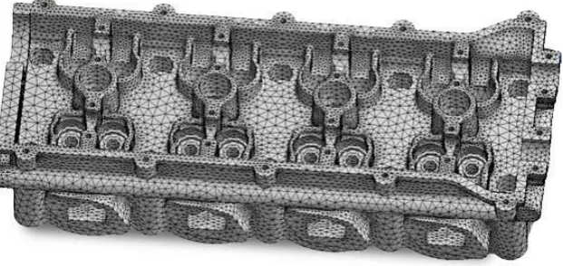
Figure 2.4: Automated structural meshing with well-shaped quadratic tetrahedral elements [22]
2.5 Meshing of interest
Following the ANSYS user manual [22], for volume meshing, a tetrahedral mesh generally provides a more automatic solution with the ability to add mesh controls to improve the accuracy in critical regions. Conversely, a hexahedral mesh generally provides a more accurate solution but is more difficult to generate.
Therefore, in this study, I have decided to choose tetrahedral meshing method to approach my challenges of simulating the air flow characteristics surrounding the stabilizer and elevator.
The reasons of choosing tetrahedral meshing method:
The geometry of the stabiliser and elevator are fairly complex.
Tetrahedral meshing is sufficient enough to produce accurate results from said geometry utilization.
The automatic solution feature will help to simplify the meshing process, thus reducing the preparation time for simulation.
In these past decades, simulation has become one of the most important essences in aerospace engineering. To be able to simulate the environment during an aircraft’s flight will give an enormous insight for aerospace engineers of what’s to expect from the actual flight practice and enables them to predict air flow characteristics and aerodynamic properties, which are exerted onto and be dealt with by the aircraft’s body structure. With such significant advantage at hand, these engineers can now redesign the aircraft’s structure and reconsider the material to be used, and with the aid of a simulation, they are able to predict the results of their innovations. As where we stand today, fuel crisis has also given a huge cost impact on well-established air transportation companies, which leads to the reconstruction of aircrafts with
increased lift power and reduced drag force. With the consideration of these factors, any improvements will surely cut down the fuel consumption of an aircraft, which will then be translated as an increase in cost efficiency.
According to a survey made by Peter and Dwight [2], a specialist in multi-disciplinary optimization who work for NASA at the time, made a plea to the CFD community, in hope that they would agree to extend their codes from simple aerodynamic analysis to sensitivity analysis. What he meant was the ability to consider evaluation of the derivatives of aerodynamic quantities, which is typically depending on both geometry and flow, with respect to some parameterization of the geometry. Furthermore, as stated in the survey, the demand for such evaluation is on the rise because the flow itself depends on the geometry over a system of partial differential equations. The request that was made, pointed out the lead of
computational solid mechanics over CFD in this respect and the significant benefits sensitivity analysis can provide to shape design through the use of gradient-based optimization. Those arguments were widely heard and in the following years, well-appreciated effort was invested in efficient and accurate evaluation of sensitivities.
The survey finalizes examples of sensitivity applications and three recent applications of gradient-based optimization were presented. The first and second applications are based on Navier-Stokes optimization of a wing-fuselage
20
Figure 2.5: DLR F6 wing-fuselage parameterization [2]
Figure 2.6: Comparison of before and after optimization [2]
The third application is based on multi-disciplinary optimization of an engine pylon, where the optimization was performed much closer to a concrete engineering application, as shown in Figure 2.7 below:
[image:33.595.121.517.445.664.2]22
It has become a norm for an engineer to use several different software products in order to generate and produce the best results with the highest analyses accuracy possible. Therefore, import or export of various data files between different software products is essential, typically importing geometry files from a design software product into a simulation software product. Though, there are already software products which integrates both design and simulation software features in a single package available on the market, that does not mean those particular software products have ever guaranteed ease of use to each and every single of its user, thus supports the increase in number of multi-software engineers.
Azamatov et al. [3] stated that geometry definition plays a key role in aircraft design, development and optimization. He then further explained, for efficient geometry generation, especially during the early stage of design, a step before the application of automated geometry generation is needed, for example, a toolbox that will produce generic and parameterized aerodynamic surfaces, which considers special requirements and constraints.
Unfortunately, of all the well-established CAD packages, very few are specialized in aircraft design. General designing systems offer solutions for
[image:34.595.180.454.530.734.2]providing data for general engineering systems and thus, could not entirely fulfil all configuration requirements of aircraft development throughout all design phases. Figure 2.8 and Figure 2.9 below show the common types of aircraft and an example of a representation of whole configuration geometry, respectively:
24
Another journal regarding specifically on the automated approach for conceptual design, which highlights the necessity of import and export of geometry to CFD grids by Tomac and Eller [10], stated that a software system known as CEASIOM, aims at automation of the computation of tables of forces and moments for rigid or elastic aircrafts with control surfaces. In order to achieve such aims, the aircraft geometry must be defined, computational meshes for aerodynamic and structural analyses need to be created, and the solver parameter settings must be adapted to reliably perform multiple solutions from which the tables are compiled.
Further discussed in their journal, the conceptual design should be projected to the following design phases in a format which enables easy application of the relevant analysis methods. The whole geometry modelling process could be performed in the CAD system, with mesh generation performed by general,
[image:36.595.115.526.465.585.2]commercial mesh generators. Figure 2.10, 2.11, and 2.12 are some of the examples of geometry models and mesh patterns for Ranger 2000 aircraft. Furthermore, major commercial efforts to speed up the CFD analysis cycle have produced significant progress towards automatic, reliable, and physics-aware mesh generation. ANSYS ICEM-CFD was stated to be one of the potential commercial products used to build unstructured tetra-hexa-prism grids for external aerodynamics analyses.
Park, DJ, Kim, CH, Jang, GH and Lee, YB, "Theoretical Considerations of Static and Dynamic Characteristics of Air Foil Thrust Bearing with Tilt and Slip Flow," Tribology International 41 (2008) p.282-295.
Jacques, E.V.P and Richard, P.D, "Numerical Sensitivity Analysis for
Aerodynamic Optimization: A Survey of Approaches," Computers & Fluids 39 (2010) p.373-391.
Azamatov, A., Lee, J.W and Byun, Y.H, "Comprehensive Aircraft Configuration Design Tool for Integrated Product and Process Development,"
Advances in Engineering Software 42 (201 1) p.35-49.
Da, X., Tao, Y. and Zhao, Z., "Virtual Flight Navier-Stokes Solver and its Application," Procedia Engineering 3 1 (20 1 2) p. 75 -79.
Vos, J.B., Rizzi, A., Darracq, D. and Hirschel, E.H., "Navier-Stokes Solvers in European Aircraft Design," Progress in Aerospace Sciences 38 (2002)
p.601-697.
Filippone, A., "Comprehensive Analysis of Transport Aircraft Flight Performance," Progress in Aerospace Sciences 44 (2008) p.192-236.
Bergmann, A. and Huebner, A., Loeser, T., "Experimental and Numerical
Research on The Aerodynamics of Unsteady Moving Aircraft," Progress in Aerospace Sciences 44 (2008) p. 12 1-137.
Dang, T.Q., and Bushnell, P.R., "Aerodynamics of Cross-Flow Fans and Their Application to Aircraft Propulsion and Flow Control," Progress in
Aerospace Sciences 45 (2009) 1-29.
Kentfield, J., "Aircraft with Outboard Horizontal Stabilizers, History, Current Status, Development Potential," Progress in Aerospace Sciences 45 (2009)
Tomac, M. and Eller, D., "From Geometry to CFD Grids - An Automated
Approach for Conceptual Design," Progress in Aerospace Sciences 47 (201 1) 589-596.
Da Ronch, A., Ghoreyshi, M. and Badcock, K.J., "On the Generation of
Flight Dynamics Aerodynamic Tables by Computational Fluid Dynamics," Progress in Aerospace Sciences 47 (201 1) 597-620.
Vallespin D, et al., "Computational fluid dynamics fi-amework for
aerodynamic model assessment," Progress in Aerospace Sciences (2012),
doi:10.1016/j.paerosci.2011.12.004.
Iosilevskii, G., "Control with Trim Tabs and History-Dependent Aerodynamic Forces," Journal of Fluids and Structures 23 c2007) 365-389.
Pereza, T. and C. Goodwin, G., "Constrained Predictive Control of Ship Fin Stabilizers To Prevent Dynamic Stall," Control Engineering Practice 16 (2008) 482-494.
Yang, W. and Yang, Z., "Schemed Power-augmented Flow for Wing-in- ground Effect Craft in Cruise," Chinese Journal of Aeronautics 24 (201 1)
119-126.
Edward Lan, C., WU, K. and YU, J., "Flight Characteristics Analysis Based on QAR Data of a Jet Transport During Landing at a High-altitude Airport," Chinese Journal of Aeronautics 25 (2012) 13-24
H. Beheshti, B., Wittmer, F. and S. Abhari, R., "Flow Visualization Study of
An Airship Model Using A Water Towing Tank," Aerospace Science and Technology 13 (2009) 450-458.
De Gregorio, F., "Flow Field Characterization and Interactional Aerodynamics Analysis of A Complete Helicopter," Aerospace Science and
Technology (201 1) doi: 10.1016/j.ast.2011.11.002.
Moormann, D., Mosterman, P.J. and Looye, G., "Object-Oriented Computational Model Building of Aircraft Flight Dynamics and Systems,"
Aerospace Science and Technology, 1999. no. 3, 1 15-126.
![Figure 2.1: Features available in ANSYS [22]](https://thumb-us.123doks.com/thumbv2/123dok_us/8771286.899050/20.595.128.519.75.321/figure-features-available-in-ansys.webp)
![Figure 2.2: Mesh parameter changes [22]](https://thumb-us.123doks.com/thumbv2/123dok_us/8771286.899050/28.595.228.407.86.266/figure-mesh-parameter-changes.webp)
![Figure 2.3: Automated hex meshing using MultiZone mesh method [22]](https://thumb-us.123doks.com/thumbv2/123dok_us/8771286.899050/29.595.169.473.257.404/figure-automated-hex-meshing-using-multizone-mesh-method.webp)
![Figure 2.5: DLR F6 wing-fuselage parameterization [2]](https://thumb-us.123doks.com/thumbv2/123dok_us/8771286.899050/32.595.148.494.86.387/figure-dlr-f-wing-fuselage-parameterization.webp)
![Figure 2.6: Comparison of before and after optimization [2]](https://thumb-us.123doks.com/thumbv2/123dok_us/8771286.899050/33.595.121.517.445.664/figure-comparison-optimization.webp)
![Figure 2.8: Common aircraft types – (a) aeroplane, (b) helicopter, (c) missile [3]](https://thumb-us.123doks.com/thumbv2/123dok_us/8771286.899050/34.595.180.454.530.734/figure-common-aircraft-types-aeroplane-helicopter-missile.webp)
![Figure 2.9: Representation of whole configuration geometry [3]](https://thumb-us.123doks.com/thumbv2/123dok_us/8771286.899050/35.595.117.519.70.580/figure-representation-configuration-geometry.webp)
![Figure 2.10: Ranger 2000 models – (a) VLM, (b) CEASIOM, (c) sumo CAD [10]](https://thumb-us.123doks.com/thumbv2/123dok_us/8771286.899050/36.595.115.526.465.585/figure-ranger-models-vlm-ceasiom-sumo-cad.webp)
