International Journal of Emerging Technology and Advanced Engineering
Website: www.ijetae.com (ISSN 2250-2459, ISO 9001:2008 Certified Journal, Volume 3, Issue 8, August 2013)
608
High-Order Current-Mode Universal Filter Using CCIIs and
Grounded Passive Components
Chen-Nong Lee1
1
Department of Computer and Communication Engineering, Taipei Chengshih University of Science and Technology, Taipei, Taiwan, R. O. C.
Abstract—This paper presents a new high-order universal filter structure with multiple-inputs and single-output. The structure only employs n second-generation current conveyors (CCIIs), n grounded capacitors, and n grounded resistors, which can realize nth-order universal filtering responses (lowpass, highpass, bandpass, band-reject, and allpass) from the same topology. Moreover, the proposed high-order filter still achieves many advantages like the employment of all grounded passive components, and the minimum number of active and passive components, in addition to having no need of inverting-type input signals or double-type input signals for the use of special input signals, no need of component matching conditions, high output impedance and low sensitivity performance. H-Spice simulation results confirm the theory.
Keywords—Active filters, second-generation current conveyors, current-mode, high-order filter, universal filter.
I. INTRODUCTION
The applications and advantages in the designing current-conveyor-based active filters have received considerable attentions. Several current-conveyor-based high-order voltage-mode or current-mode filters have been presented in the literature [1-7]. Such structures have often been developed with different design criteria in mind, including the realization of all five universal filtering responses, reduced number of active and passive elements, and employment of grounded passive elements. Using signal-flow graph approach, several high-order transfer function syntheses using CCIIs have been present [1-3].
For example, In [1], a nth-order allpass voltage-mode filter
was proposed. The allpass filter employs n+1
current-conveyors, n-1 floating and one grounded capacitors, and 2n+1 floating and two grounded resistors. In [2], a n th-order lowpass voltage-mode filter was proposed. The lowpass filter contains n current-conveyors, n capacitors (only one capacitor grounded), and n floating resistors. In [3], a general synthesis method for the realization of n th-order voltage transfer function was proposed. The filter
structure employs n+2 current-conveyors, n capacitors
(only one capacitor grounded), and 2n+3 resistors (only one
resistor grounded).
However, all these filter structures [1-3] use many floating passive elements. Since the circuits using only grounded passive elements have many advantages in integrated circuit (IC) realization, some high-order voltage-mode or current-voltage-mode current-conveyor-based filters using only grounded passive elements have been presented in [4-6].
The recently reported two high-order
current-conveyor-based current-mode filters [4, 5] employs only n grounded
capacitors [4, 5], and n grounded resistors [4], (i.e. the minimum number of passive components). However, the
two high-order filter structures need to use either n+1
current-conveyors [4] or n+1 current-controlled conveyors
(CCCIIs) [5]. Moreover, they can not realize high-order allpass response. In 2009, a good high-order current-mode and transimpedance-mode (i.e. input as current and output as voltage) universal filter was proposed in [7]. The filter can realize lowpass, bandpass, highpass, band-reject, and allpass responses from one current-output terminal and one voltage-output terminal but it needs to use n+1 MOCCIIs
and one floating resistor, in addition to n grounded
capacitors and n grounded resistors. In 2011, two digitally
programmable high-order current-mode universal filter structures were presented [8]. However, they need to use 2n+3 or 3n+2 active elements, 2n or 2n-1 floating resistors, and n grounded capacitors. Only one [6] can realize high-order current-conveyor-based voltage-mode allpass transfer function with the minimum number of active and grounded
passive components (i.e. only n current conveyors, n
grounded capacitors, and n grounded resistors). In [6],
Chang and Swamy use the very effective analytical synthesis method (ASM) [6, 9-15] to synthesize a new current-conveyor-based high-order allpass filter structure which can achieve all of the main advantages. Up until now, no current-conveyor-based high-order universal filter (lowpass, bandpass, highpass, band-reject, and allpass) using the minimum number of active and grounded passive
components (i.e. only n CCIIs, n grounded capacitors, and
International Journal of Emerging Technology and Advanced Engineering
Website: www.ijetae.com (ISSN 2250-2459, ISO 9001:2008 Certified Journal, Volume 3, Issue 8, August 2013)
609
Current-mode filters using current-conveyors have received considerable attention, because they have higher signal bandwidths, greater linearity, lower power consumption, and larger dynamic range than the voltage-mode counterparts [16, 17]. Since the OTA has high input and output impedances, it is more suitable for transadmittance-mode (i.e. input as voltage and output as current) circuit applications Also, the OTA will pose a stability problem at high frequencies [4]. Since the CCII has unity voltage and current gains, it has not such a problem [4]. Hence, this leads to prospective research work: investigating and developing a high-order CCII-based filter which can realize nth-order universal filtering responses (lowpass, highpass, bandpass, band-reject, and allpass) from the same topology using the minimum number of active and grounded passive components (i.e.
only n CCII, n grounded capacitors, and n grounded
resistors) without requiring matching conditions and inverting or double-types amplifiers for special input signals.
In this paper, the proposed structure is a new high-order
current-mode universal filter using only n CCIIs, n
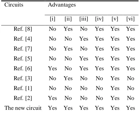
grounded capacitors, and n grounded resistors. In Table I, the main features of the proposed new high-order circuit are compared with those of previous high-order works as following advantages: (i) the minimum number of active
components, (ii) the realization of nth-order universal
filtering responses (lowpass, highpass, bandpass, band-reject, and allpass) from the same topology, (iii) the employment of all grounded passive components, (iv) no need to impose components choice conditions to realize
specific nth-order filtering functions, (v) no need of
inverting-type or double-type amplifiers for the use of special input signals, (vi) low active and passive sensitivities.
II. HIGH-ORDER CURRENT-MODE UNIVERSAL FILTER
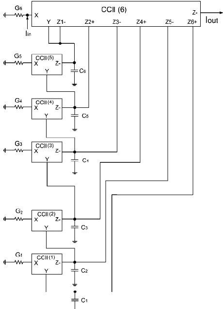
Figure 1 shows the proposed nth-order filter structure where In, In-1, In-2 ,…, I2, I1, I0 are the filter input currents whose setting determine the filter functions as shown later, Iout is the filter current output. The choice of the subscript +/- of the output terminal Zn+/- in the CCII(n) depends on an
even/odd order n of the high-order filter, respectively.
Using standard notation, the port relations of a CCII can be characterized by IY = 0, VX = VY and IZ± = ±IX. The
multiple current outputs of CCII(n) can be simply
reconstructed using current mirrors. Moreover, all current outputs have very high output impedance.
TABLEI
PERFORMANCE PARAMETERS OF RECENTLY REPORTED HIGH-ORDER CURRENT-CONVEYOR BASED FILTERS
Circuits Advantages
[i] [ii] [iii] [iv] [v] [vi]
Ref. [8] No Yes No Yes Yes Yes
Ref. [4] No No Yes Yes Yes Yes
Ref. [7] No Yes No Yes Yes Yes
Ref. [5] No No Yes Yes Yes Yes
Ref. [6] Yes No Yes Yes Yes Yes
Ref. [3] No Yes No No Yes No
Ref. [1] No No No No Yes No
Ref. [2] Yes No No No Yes No
The new circuit Yes Yes Yes Yes Yes Yes
Routine circuit analysis for Figure 1 yields the following transfer functions:
0 1 2 2 2 2 1 1
0 0 1 1 2 2 2 2 2 2 1 1 1
... ...
a s a s a s
a s a s a
I a s I a s I a s
I a s I a s I a I
n n n n n n
n n n n n n n n n out
(1) Where
n
i i
n C
a
1
,
n
k
j j
k
i i
k C G
a
1 1
for k1,2,3,...,n1
n
j j
G a
1 0
The choice of the +/- of (a0I0) term is based upon an
even/odd order n of the high-order filter, respectively.
From equation (1), the high-order universal filter transfer functions are obtained according to input current conditions as follows.
(i) Highpass: In = Iin , and all the other input currents are zero.
(ii) Lowpass: I0 = Iin , and all the other input currents are zero.
[image:2.612.326.561.168.360.2]International Journal of Emerging Technology and Advanced Engineering
Website: www.ijetae.com (ISSN 2250-2459, ISO 9001:2008 Certified Journal, Volume 3, Issue 8, August 2013)
610
(iv)Band-reject: In = I0 = Iin , and all the other input currents are zero.
[image:3.612.56.281.160.506.2](v) All-pass: In = In-1 = In-2 =…= I2 = I1 = I0 = Iin.
Figure 1. Proposed current-mode nth-order universal filter structure.
Note that there are no critical component-matching conditions or cancellation constraints in the design. Moreover, the structure does not need inverting-type input current signals or double-type amplifier for realizing any filter transfer functions. Note that by adding an extra Z- terminal to the CCII(n) (i.e. multiple current outputs CCII) and then adding an extra grounded resistor to this Z- terminal, the proposed circuit can also realize current-mode
and transimpedance-mode nth-order universal filtering
responses (lowpass, highpass, bandpass, band-reject, and allpass) from one current-output terminal (Iout , shown in Figure 1) and one voltage-output terminal (i.e. the extra Z-terminal ) without using additional active elements and floating passive elements.
[image:3.612.327.557.232.550.2]With respect to the high-order current-mode and transimpedance-mode filters in [7], the new proposed structure uses one fewer CCII and no floating passive elements. To illustrate the proposed current-mode high-order filter structure, Figure 2 shows a sixth-high-order highpass filter with low input and high output impedance suitable for direct cascading and easy to be connected to next stage without any buffer.
Figure 2. Proposed sixth-order high-pass current-mode filter.
III. NONIDEAL ANALYSIS
Taking the tracking errors of the CCII into account, the relationship of the terminal voltages and currents can be written as: IY = 0, VX = β(s)VY, IZ± = ±α(s)IX, where α(s) and β(s) represent the frequency transfer functions of the internal current and voltage followers of the CCII. They can be approximated by the first order lowpass functions
[18, 19], whose corner frequencies 300MHz by using
International Journal of Emerging Technology and Advanced Engineering
Website: www.ijetae.com (ISSN 2250-2459, ISO 9001:2008 Certified Journal, Volume 3, Issue 8, August 2013)
611
For frequencies much less than the corner frequencies of the CCII, all α(s) and β(s) are real quantities of magnitudes slightly less than one [18, 19]. Assuming the circuit works
at frequencies much less than the corner frequencies of α(s)
and β(s), namely, α(s) = α = 1-εi and εi (εi << 1) denotes the current tracking error and β(s) = β = 1-εv and εv (εv << 1) denotes the voltage tracking error of the CCII.
Taking into account the non-idealities [18, 19] of the
CCII(n), CCII(n-1),……, CCII(2), CCII(1), we obtain the
non-idealities as below:
0 Y
I ,VX nVY,IZn0IX,IZ1n1IX,
X n
Z I
I 2 2 ,IZ3 an3IX,…..,IZnnnIX for CCII(n) (2)
0 Y
I ,VX n1VY, IZ(n1)0IX
for CCII(n-1) (3) 0
Y
I ,VX n2VY, IZ(n2)0IX
for CCII(n-2) (4)
0 YI ,VX 2VY, IZ20IX
for CCII(2) (5)
0 Y
I ,VX 1VY, IZ10IX
for CCII(1) (6)
The non-ideal denominator of the nth-order universal
filter transfer function shown in equation (1) becomes
0 1 2 2 1
1
'
'
'
'
'
)
(
s
a
s
a
s
a
s
a
s
a
D
n n
n n
(7) Let 0 0 1 1 2 2 2 2 1 1 ' ' , ' ' , ' ' ,..., ' ' , ' ' A a a A a a A a a A a a A a a n n n n n n n n
n
(8) We can obtain that:
n n nn n n n n n n C C C C C G G G G G A 1 3 2 1 0 ) 1 ( 0 ) 2 ( 30 20 10 1 3 2 1 1 3 2 1 0 .... .... .... .... (9) n n n n n n n n n n C C C C C G G G G G A 1 4 3 2 ) 1 ( 0 ) 1 ( 0 ) 2 ( 40 30 20 1 4 3 2 1 4 3 2 1 .... .... .... .... (10) n n n n n n n n n n C C C C C G G G G G A 1 5 4 3 ) 2 ( 0 ) 1 ( 0 ) 2 ( 50 40 30 1 5 4 3 1 5 4 3 2 .... .... .... .... (11)
n n n n n n n n n n n n n C C C G G G A 1 2 3 0 ) 1 ( 0 ) 2 ( 1 2 1 2 3 (12) n n n n n n n n n C C G G A 1 2 0 ) 1 ( 1 1 2 (13) n n n n n C GA 1 1 (14)
The relative sensitivities are the values of filter characteristic parameters (An-1, An-2 ,…, A2, A1, A0) with respect to circuit elements. By using equations (9)–(14), the sensitivities of filter characteristic parameters (An-1, An-2 ,…,
A2, A1, A0) can easily be calculated and equal to 0 or 1. All of which are small.
If a second-order filter (n = 2) is given as an example, the equations (7)–(14) are obtained as below:
2 1 2 1 22 10 2 1 2 2 21 2 2 ) ( C C G G C G s s s
D (15)
The ω0 and Q of the non-ideal current-mode universal biquad are: 2 1 2 1 22 10 2 1 0 C C G
G
(16)
1 2 2 2 1 1 10 22 21 1 C G C G Q
(17)
The active and passive sensitivities of ω0 and Q are:
2 1 0 2 1 22 10 0 2 1 0 2
1, , , , ,
SC C SG G S
2 1 2 1 10 22 2 1 1
2, , , ,
Q Q Q
G C Q
G
C S S S
S
1
21
Q
S
0 0 23 21 2011, , , a S
0
23 20 11, ,
Qa
International Journal of Emerging Technology and Advanced Engineering
Website: www.ijetae.com (ISSN 2250-2459, ISO 9001:2008 Certified Journal, Volume 3, Issue 8, August 2013)
612
In summary, the proposed current-mode universal filter has low active and passive sensitivities.
IV. H-SPICE SIMULATIONS
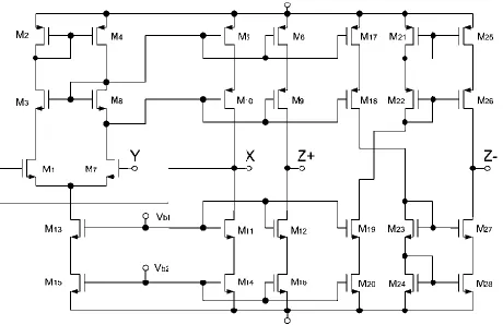
A CMOS implementation of the CCII± is shown in
Figure 3 [20] with the NMOS transistor aspect ratios (W/L=5μm/1μm) and PMOS transistor aspect ratios (W/L=10μm/1μm). Note that the multiple current outputs of CCII applying the realization of current replicas are very simple. To verify the theoretical analysis of the high-order universal filters, the H-SPICE simulations, using the TSMC 0.25μm process with the parameters of level 49 for the proposed circuits of Figure 1, were performed with the component values: R1 = R2 = … = R5 = R6 = 10kΩ, and C1 = C2 = … = C5 = C6 = 5pF for the sixth-order high-pass, low-pass, band-pass, and band-reject filters of the Figure 1,
leading to a center frequency of f0 = 3.183MHz, and (ii) C1
= C2 = C3 = 5pF, R1 = 20kΩ, R2 = 10kΩ, and R3 = 5kΩ for the third-order all-pass filter of the Figure 1, leading to a center frequency of f0 = 3.183MHz. Their supply voltages
are VDD =-Vss = 1.25V, Vb1 = -0.3V, and Vb2 = -0.6V.
[image:5.612.332.542.146.310.2]Figure 4 presents the simulated sixth-order highpass, lowpass, bandpass, and band-reject amplitude-frequency responses. Figure 5 presents the simulated third-order all-pass phase and amplitude-frequency responses. As can be seen, there is a close agreement between theory and simulation.
Figure 3. CMOS implementation of the CCII±.
105 106 107 -200
-180 -160 -140 -120 -100 -80 -60 -40 -20 0
frequency(Hz)
m
a
g
n
it
u
d
e
(d
b
)
Figure 4. Amplitude-frequency responses of the proposed current-mode sixth-order high-pass, low-pass, band-pass, and band-reject
signals (*, simulated high-pass response; Δ, simulated low-pass response; ○, simulated band-pass response; ×, simulated band-reject
response; and ____,theoretical curve ).
104 105 106 107 -400
-300 -200 -100 0 100 200
frequency(Hz)
p
h
a
s
e
(d
e
g
re
e
)
m
a
g
n
it
u
d
e
(d
b
)
20
10
0
-10
-20
-30
-40
Figure 5. Phase-frequency and amplitude-frequency responses of the proposed current-mode third-order all-pass signals (○, simulated
phase; Δ, simulated amplitude; and ____,theoretical curve).
V. CONCLUSIONS
Using n CCIIs, n grounded capacitors, and n grounded resistors, a current-mode universal high-order filter is
presented which can realize nth-order low-pass, high-pass,
[image:5.612.341.549.381.534.2] [image:5.612.55.285.464.613.2]International Journal of Emerging Technology and Advanced Engineering
Website: www.ijetae.com (ISSN 2250-2459, ISO 9001:2008 Certified Journal, Volume 3, Issue 8, August 2013)
613
Moreover, the proposed high-order circuit offers the following advantages: the minimum components, using grounded capacitors attractive for integration, using grounded resistors suitable for the variation of filter parameters, high output impedance good for cascadability, no need to change the filter topology, no component-value constraints, no need of inverting or double-type amplifiers for special input signals, and low active and passive sensitivities. H-Spice simulations with TSMC 0.25μm process and ±1.25V supply voltages are included and confirm the theoretical predictions.
Acknowledgements
The author would like to thank the National Science Council of Taiwan, R. O. C. The National Science Council, Republic of China supported this work under grant number NSC 101-2221-E-149-008-.
REFERENCES
[1] C. Acar, ―Nth-order allpass voltage transfer function synthesis using CCII+s: Signal-flow graph,‖ Electronics Letters, Vol. 32, No. 8, 1996, pp. 727-729.
[2] C.Acar, ―Nth-order lowpass voltage transfer function synthesis using CCII+s: signal-flow graph approach,‖ Electronics Letters, Vol. 32, No. 3, 1996, pp. 159-160.
[3] C. Acar and S. Özoğuz, ―High-order voltage transfer function synthesis using CCII+ based unity gain current amplifiers,‖ Electronics Letters, Vol. 32, No. 22, 1996, pp. 2030-2031. [4] E. Yuce and S. Minaei, ―ICCII-based universal current-mode analog
filter employing only grounded passive components,‖ Analog Integrated Circuits and Signal Processing, Vol. 58, No. 2, 2009, pp. 161-169.
[5] E. Yuce and S. Minaei, ―On the realization of high-order current-mode filter employing current controlled conveyors,‖ Computers & Electrical Engineering, Vol. 34, No. 3, 2008, pp. 165-172.
[6] C. M. Chang, A. M. Soliman, and M.N.S. Swamy, ―Analytical synthesis of low-sensitivity high-order voltage-mode DDCC and FDCCII-grounded R and C all-pass filter structures,‖ IEEE Transactions on Circuits and Systems-Part I: Regular Papers, Vol. 54, No. 7, 2007, pp. 1430-1443.
[7] J. W. Horng, ―High-order current-mode and transimpedance-mode universal filters with multiple-inputs and two-outputs using MOCCIIs,‖ Radioengineering, Vol. 18, No. 4, 2009, pp. 537–543.
[8] H. A. Alzaher, N. A. Tasadduq, and O. Al-Ees, ―Digitally programmable high-order current-mode universal filters,‖ Analog Integrated Circuits and Signal Processing, Vol. 67, No. 2, 2011, pp. 179-187.
[9] C. M. Chang, and B. M. Al-Hashimi, ―Analytical synthesis of current-mode high-order OTA-C filters‖, IEEE Trans. Circuits Syst. I: Fundam. Theory Appl., vol. 50, no. 9, 2003, pp. 1188-1192. [10] C. M. Chang, B. M. Al-Hashimi, Y. Sun, and J. N. Ross, ―New
high-order filter structures using single-ended-input OTAs and grounded capacitors‖, IEEE Trans. Circuits Syst. II: Exp. Briefs, vol. 51, no. 9, 2004, pp. 458-463.
[11] C. M. Chang, C. L. Hou, W. Y. Chung, J. W. Horng, and C. K. Tu, ―Analytical synthesis of high-order single-input OTA-grounded C all-pass and band-reject filter structures‖,IEEE Trans. Circuits Syst. I: Fundam. Theory Appl., vol. 53, no. 3, 2006, pp. 489-498. [12] C. M. Chang, ―Analytical synthesis of the digitally programmable
voltage-mode OTA-C universal biquad‖, IEEE Trans. Circuits Syst. II: Exp. Briefs, vol. 53, no. 8, 2006, pp. 607-611.
[13] S. H. Tu, C. M. Chang, N. J. Ross, and M. N. S. Swamy, ―Analytical synthesis of current-mode high-order single-ended-input OTA and equal-capacitor elliptic filter structures with the minimum number of components‖, IEEE Transactions on Circuits and Systems-Part I: Regular Papers, vol. 54, no. 10, 2007, pp.2195-2210.
[14] C. M. Chang, and M. N. S. Swamy, ―Analytical synthesis and comparison of voltage-mode nth-order OTA-C universal filter structures‖, International Journal of Circuit Theory and Applications, Vol. 40, No. 5, 2012, pp. 421-454.
[15] C. M. Chang, and M. N. S. Swamy, ―Analytical synthesis of odd/even-nth-order elliptic Cauer filter structures using OTRAs‖, International Journal of Circuit Theory and Applications, Article first published online: 21 September 2012.
[16] G. W. Roberts, A. S. Sedra, ―All current-mode frequency selective circuits,‖ Electronics Letters, Vol. 25, No. 12, 1989, pp. 759–761. [17] B. Wilson, ―Recent developments in current conveyors and
current-mode circuits,‖ IEE Proceedings G Circuits, Devices & Systems, Vol. 137, No. 2, 1990, pp. 63–77.
[18] A. Fabre, O. Saaid, and H. Barthelemy, ―On the frequency limitations of the circuits based on second generation current conveyors,‖ Analog Integrated Circuits and Signal Processing, Vol. 7, No. 2, 1995, pp. 113-129.
[19] J. W. Horng, C. L. Hou, C. M. Chang, W. Y. Chung, and H. Y. Wei, ―Voltage-mode universal biquadratic filters with one input and five outputs using MOCCIIs,‖ Computers and Electrical Engineering, Vol. 31, No. 3, 2005, pp. 190-202.