Green Antenna and Radio over Fiber Technology for a Cellular Wireless
1
Abhijeet gupta,Research scholar,Mewar university, chittorgarh ,Rajasthan,INDIA
2
Dr.Sudhir kumar,RKDFIST,Bhopal,INDIA ,
Email id:
1[email protected],
2
[email protected]
Now a day's, the main problem in the mobile Abstract communication networks is, in addressing the problem of reduction of the power consumption as well as RF radiations from the base stations (BS)/antennas, which are harmful to the people in the surrounding locations. Cellular phones have become an essential part of modern life. Energy consumption of communication networks and emissions from base stations (BSs) and mobile stations (MSs) has received increased attention. To minimize the human exposure to RF radiation, transmit powers of BS as well as MS has to be reduced or BSs has to be placed far away from the densely populated areas. The Mobile operators are facing challenges and competition in providing high data rate services as well as coverage to the users instead of very high maintenance cost. Modulation of RF subcarrier onto optical carrier over a optical fiber network is called “Radio over Fiber Technology (RoF)”. For the above problems, RoF is one of the efficient solutions. Integration of wireless communications and fiber optics provides coverage for outdoors as well as indoors such as inside the buildings, tunnels, shopping malls, airports etc, in a cost effective manner. RoF supports wideband signals like UMTS and WiMAX. In this paper, overview of Radio over fiber (RoF) technology for mobile networks has been presented and power reduction in the uplink and downlink transmission has been shown.
Index Terms— WCDMA, Radio Over Fiber, Wimax, UMTS, QPSK.
I. INTRODUCTION
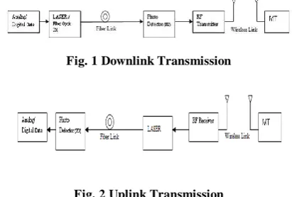
The general architecture of RoF for downlink transmission and uplink transmission is shown in figures 1 and 2. RoF technology has decreased the cost of BS (Base Station) replacing it with Control Station/Central Office (CS/CO) which is MSC (Mobile Switching Center), where transmission process is carried out which includes coding, multiplexing, RF transmission etc. making BS design and circuitry very simple consisting of O/E converter (optical - electrical) and E/O converter (electrical - optical) and amplifiers if needed. In order to provide the latest technology facilities to the mobile subscribers which include high data rates and increasing demand for multimedia, coverage and capacity parameters of cellular operators using different schemes, modulation techniques, dynamic allocations leads to complexity at the Base Station (BS) as well as it costs a lot. An alternative for this complexity at the BS is, the use of RoF technology where BS complexity is shifted to Control Station (CS). All the signal processing, dynamic resource allocation – coding, RF generation, modulation, up/down conversions (if IF is used) everything will be carried out at CS reducing
[image:1.596.322.528.264.403.2]the complexity at Radio Access Points (RAP) i.e., which acts as BS in cellular networks for transmission and receiving purpose. These RAPs are equipped with E/O, O/E converters, antenna and amplifiers.
Fig. 1 Downlink Transmission
Fig. 2 Uplink Transmission
consisted by transmitted signal depends on refractive indices – limits the transmission distance. Waveguide dispersion occurs due to waveguide structure, shape of the fiber (core and cladding). In case of MMF, LEDs are used to couple light because of low coupling loss and semiconductor lasers are used to couple light in SMF for long distance transmission. Modulation of the signal is carried out in two ways: Direct Intensity Modulation - by turning on and off the laser, signal is modulated. DM leads to frequency chirp. External modulation - modulating the light externally coming from the laser. Remote Heterodyning – optical signals are generated from laser and modulated by information signal and are heterodyned. For high bit rates above 10 Gbps and for frequencies above 10GHz, external modulation is preferred. Direct detection process is employed at the receiver side by using PIN photodiode or PN photodiode. In RoF, for downlink external modulation or direct intensity modulation is preferred depending upon the requirement and for uplink direct intensity modulation is preferred.
A. Radio over Fiber
Radio over Fiber (RoF) application has attracted much attention recently because of the increasing demand for capacity/coverage and the benefits it offers in terms of low-cost base station deployment in macro cellular system. RoF systems are now being used extensively for enhanced cellular coverage inside buildings such as office blocks, shopping malls and airport terminals etc. RoF is fundamentally an analog transmission system because it distributes the radio waveform, directly at the radio carrier frequency, from a central unit to a Radio Access Point (RAP). Note that although this transmission system is analog, the radio system itself may be digital such as GSM. Mainstream optical fiber technology in digital Telecommunication networks, use synchronous digital hierarchy (SDH) transmission technology in their cores. Fiber-based data networks such as fiber distributed data interface (FDDI) and gigabit Ethernet all use digital transmission. Fiber transmission links to base stations in mobile communications systems are digital. Digital optical fiber transmission links are therefore ubiquitous in telecommunications and data communications, constituting a high volume market worth billions of dollars worldwide.
B.Wideband Code Division Multiple Access
Wideband Code Division Multiple Access (WCDMA), air interface is now regarded as a mature technology ready to provide the basis for the third generation wireless personal communication systems, known’s as “universal Mobile Telecommunication Systems (UMTS) (3G). These systems will make extensive use of microcells and picocells in order to deliver high bandwidth services to customers. WCDMA is also known as Third Generation System (3G). The systems are designed for multimedia communication, can be enhanced with high quality images and video and access to information and services on public and private networks will
483
be enhanced by the higher data rates and new flexible communication capabilities of third generation systems (3G). This together with the continuing evolution of the second-generation systems (2G) will create new business opportunities for manufacturers, operators and the providers of content and applications using these networks. In the standardization forum, WCDMA technology has emerged as the most widely adopted third generation air interface. Its specification has been created in 3GPP (the 3rd Generation Partnership Project), which is the joint standardization project of the standardization bodies from Europe, Japan, Korea, the USA and China. Within 3GPP, WCDMA is called UTRA (Universal Terrestrial Radio Access). WCDMA is being used to cover both FDD (Frequency Division Duplex) and TDD (Time Division Duplex) operation. The benefit of using RoF for WCDMA distributed antenna systems is expected to be even more important, partly because of their higher frequency and bandwidth requirements. In this paper, the simulation of WCDMA RoF using Matlab has been successfully developed. The complete simulink block has been successfully compiled-processed and obtained BER performance is obtained to rate it.
C. Merging of the Wireless and Fiber Optics World
484
CS, where all switching, routing, media access control (MAC) and frequency management functions are performed, and an optical fiber network, which interconnects a large number of functionally simple and compact antenna BSs for wireless signal distribution. The BS has no processing function and its main function is to convert optical signal to wireless one and vice versa. Since RoF technology was first demonstrated for cordless or mobile telephone service in 1990, a lot of research efforts have been made to investigate its limitation and develop new, high performance RoF technologies. Their target applications range from mobile cellular networks wireless local area network (WLAN) at mm-wave bands [5], broadband wireless access networks to road vehicle communication (RVC) networks for intelligent transportation system (ITS). Due to the simple BS structure, system cost for deploying infrastructure can be dramatically reduced compared to other wire line alternatives. In addition to the advantage of potential low cost, RoF technology has further the benefit of transferring the RF signal to and from a CS that can allow flexible network resource management and rapid response to variations in traffic demand due to its centralized network architecture.
II. SYSTEM MODEL
The main objective of this paper is to move around the minimization of the transmit power from the base station as well as the mobile terminal, which leads to the low h ealth impairments as well as the less effective to the environment. Using RoF technology as the transmission medium for RF signals for communication – data, voice, multimedia etc, minimizes usage of high as well as complex components at the base station termed as RAU(Radio Access Unit), making the base station part in a very simple way – integrating the processes (modulation, signal processing etc) to be carried out in base station has been shifted to CBS (Central Base Station) or CS (Control Station). Keeping in view the above considerations, work/study has been carried out to propose an architecture which provide a system with better performance (low transmit power and signal quality). In this study, WCDMA system parameters have been considered for system simulations. In order to show the architecture with RoF technology, green antenna - is a distributed antenna with disabled transmission capability, but in this study green antenna is considered for both transmission and reception purpose. Simulation has been done for uniformly distributed users in the cell of 1.8km, placing the green antenna at 30% of the maximum radius at the centre of the cell sector. Cell has been sectored for three types – 3, 4 and 6 sectors per cell and successfully shown that capacity of a cell can be increased with very low transmit power. Next part of the study, deals with the performance of WCDMA transmission over RoF for signal quality. Generation of spreading code (M sequence, Gold and Orthogonal gold sequences) and including Rayleigh fading in the simulation has been carried
out and system is found to be providing the almost same signal quality in RoF (low transmit power) and better one compared to the direct transmission of the WCDMA.
A. Cell Architecture
[image:3.596.325.522.161.316.2]Block diagram of WCDMA transmission using RoF technology, which is being used for the simulation process is shown below
Fig 3: WCDMA transmission over fiber
WCDMA air interface is now regarded as a mature technology ready to provide the basis for the third generation wireless personal communication systems, known as
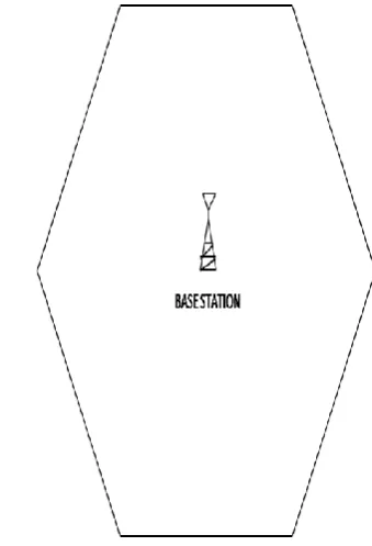
Universal Mobile Telecommunication Systems (UMTS) (3G). These systems will make extensive use of microcells and picocells in order to deliver high bandwidth services to customers. Basic cell architecture with single base station is shown below.
Fig 4: Basic cell architecture with base station
[image:3.596.331.501.422.671.2]Transmit Power - MS, BS -20 dBm to + 20dBm, -25 dBm to +25 dBm
Receiver Sensitivity - MS, BS -10 dBm, -129 dBm
Cell Radius (CR) 1.8 km
Cell Sectoring 120(degree), 90(degree),
160(degree)
RAU- Green Antenna 30% of CR, 40% of CR, 50%
of CR
Users Uniformly distributed -200
Fiber Loss 0.2 dB/Km
Path Loss Model Okumura Hata Model
Carrier Frequency 2100 Mhz
Data Modulation QPSK
Spreading M-Sequences, Gold Sequences,
Orthogonal Gold Sequences
Channel Bandwidth 5 MHz
Chip Rate 3.84 Mcps
Data Rate 384 Kbps/ 2 Mbps
Filter Taps 21
Over Samples 8
Noise Gaussian
Fading Rayleigh
Fiber Loss 0.2 dB/Km
Noise(Shot, Dark, Thermal )
4.44×10⁻⁴
Laser Power Input, Pin 1 mW, 10 mW
Wavelength 1550 nm
P
e
rc
en
tag
e
o
f
U
s
e
rs
c
o
v
e
re
d
P
er
c
en
tag
e
o
f
U
s
er
s
c
o
v
e
re
d
485
A. Downlink:
[image:4.596.89.243.89.286.2]Reduced transmission power with RoF technology has showed a wide difference in terms of coverage, data rate and BER. In the downlink transmission, there is a 12dBm -15dBm (on an average) difference in transmission power comparatively to direct transmission of signals. This is shown in figure 6. If sectoring is considered - three sectors per cell, four sectors per cell and six sectors per cell, there is more improvement in the performance, but according to the results obtained four cell sectoring is optimum among the three and six sectors per cell. For more coverage six sectors per cell can be used, but there will be a extra cost with less improvement in the performance comparatively to the 4 sectors. In the simulation process, users are uniformly distributed in the cell and Gaussian random variable with zero mean and 8dB standard deviation is considered. The
Fig 5: RoF cell architecture with 6 sectoring maximum cell radius is 1.8km.
B. System Parameters
Table 1. Simulation Parameters for Power Efficiency using Green Antenna [1][16]
1
0.9
0.8
Transmit Power(dBm) versus Percentage of Users covered
(Downlink) Cell without green antenna Cell with green antenna Cell with green antenna S-3 Cell with green antenna S-4 Cell with green antenna S-6
0.7
0.6
0.5
0.4
0.3
0.2
0.1
Table 2. Simulation Parameters for Eb/No vs BER [1][10][15][16]
0
-25 -20 -15 -10 -5 0 5 10 15 20 25 Transmit power in dBm at BS
Fig 6: Power efficiency for Downlink Transmission
B. Uplink:
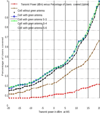
In the case of Uplink, there is a 10dBm – 14dBm (on an average) difference in the transmission power. From figure 7, it can observe that almost same performance is shown by four and six sectors per cell and among three, four and six sectors per cell – four sectors per cell is the optimum.
1
Transmit Power (dBm) versus Percentage of Users covered (Uplink)
Cell without green antenna Cell with green antenna 0.9
Cell with green antenna S-3 Cell with green antenna S-4 0.8 Cell with green antenna S-6
0.7
0.6
0.5
0.4
III. SYSTEM SIMULATION
Simulation has been computed for transmit power against percentage of users covered for general cell architecture which is being compared to the RoF technology without cell sectoring and with cell sectoring for both downlink and uplink transmissions.
0.3
0.2
0.1
0
-20 -15 -10 -5 0 5 10 15 20
[image:4.596.350.503.299.465.2]Transmit power in dBm at MS
[image:4.596.343.504.571.754.2]B
ER
P
e
rc
en
tag
e
o
f
U
s
e
rs
C
o
v
e
re
d
486
. Varying Green Antenna distance in Six Cell Sectoring:
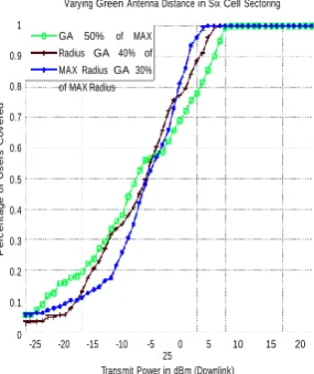
The performance of the system with six sectors per cell using RoF is studied. The plot of the system is shown in figure 8, in which RAU (green antenna) is placed – firstly at the 30% of the maximum radius and simulation is performed, then GA is placed at 40% of the maximum radius and simulation is carried out and also for the GA placed at 50% of the maximum radius is simulated.
Varying Green Antenna Distance in Six Cell Sectoring
From figure 3.6, it can be observed that with less transmit power more coverage is attained. Thus, it is possible to provide better or same signal quality under RoF technology transmission with less transmit power.
IV. CONCLUSION
Cellular architecture with RoF technology has showed promising power reduction in the emissions from the MS and BS, leading to be less harmful to mobile users and humans
1
0.9
0.8
0.7
0.6
0.5
0.4
0.3
0.2
0.1
0
GA 50% of MAX Radius GA 40% of MAX Radius GA 30% of MAX Radius
nearby. The architecture of RoF does not require network replacement, but coverage and network can be easily augmented with green antennas in the network. With the reduced transmit power and increased coverage provided by using RoF technology, WCDMA transmission over RoF provide better – almost same signal quality in terms of BER with less power. RoF technology playing a very important role in cellular communications today and become even more prevalent in the future. Research can be carried out for latest technologies emerging in wireless world say LTE, LTE – A, IMT, IMT - A (4G). OFDM is seen as the modulation
-25 -20 -15 -10 -5 0 5 10 15 20
[image:5.596.95.238.185.355.2]25 Transmit Power in dBm (Downlink)
Fig 8: Power efficiency by varying GA distance for Downlink Transmission
It is observed from the figure 3.5, that there is an improvement in the capacity of the network, as the antenna distance is moving away from the center of the cell (CBS) i.e., for green antenna placed at 50% of maximum radius provide better performance comparatively to green antenna placed at 30% and 40% of the maximum radius.
D: EbNo vs BER for WCDMA under Direct and RoF
technology Transmission:
Figure 9 depicts that, WCDMA transmission under RoF technology has very less improvement over the WCDMA direct transmission.
technique for future wireless communications because it provides increased robustness against frequency selective fading and narrowband interference and is efficient in dealing with multi-path delay spread. So a study can be conducted to access the usefulness of Green Antenna with RoF technology where it uses OFDM modulation technique.
REFERENCES
[1] Green Cellular – Optimizing the Cellular Network for Minimal Emission from Mobile Stations, Doron Ezri and Shimi Shilo, June 2009.
[2] Transmission of UMTS and WIMAX signals over Cost-Effective Radio Over Fiber Systems, Davide Visani, Giovanni Tartarini, Luigi Tarlazzi and Pier Facing, IEEE Microwave and Wireless Components Letters, Vol. 19, No. 12, December 2009.
Performance study of BER vs EbNo for WCDMA under Direct Transmission and ROF Transmission 0
10
-1 10
ROF for WCDMA Direct WCDMA
[3] I. Harjula, A. Ramirez, F. Martizez, D. Zorrilla, M. Katz, and V. Polo, “Practical issues in the combining of MIMO techniques and RoF in OFDM/A systems.” in Proc. 7th WSEAS Int. Conference. on Electron, Hardwar, Wireless and Opt. Comm., Cambridge, UK, February 20-22, 2008, pp. 244-248.
-2 10
-3 10
-4 10
-5 10
0 2 4 6 8 10 12 14 16 18 20 EbNo (dBm)
[4] G. Singh, and A. Alphones “Optical transmission performance of a radio-over-fiber system for wireless LAN,” in Proc. 6th International Conf. on Info. Comm. and Sig. Process., Singapore, December 10-13. 2007.
[5] Analysis of OFDM signals through optical fiber for Radio-over-Fiber transmission, Dhivagar. B, Ganesh Madhan. M, Xavier Fernando, Ryerson University, IEEE 2006.
[image:5.596.93.248.536.713.2][6] Analysis of OFDM signals through optical fiber for Radio-over-Fiber transmission, Dhivagar. B, Ganesh Madhan. M, Xavier Fernando, Ryerson University, IEEE 2006.
487
[7] Radio over fiber for beyond 3G, Kwansoo Lee,
Telecommunication R&D Center, Samsung Electronics, IEEE 2005.
[8] J. S. Yoon, M. H. Song, S. H. Seo, Y. S. Son, J. M. Cheong and Y. K. Jhee, .A High-Performance Fiber-Optic Link for cdma2000 Cellular Network,. IEEE Photon. Technol. Lett., vol. 14, no. 10, pp. 1475.1477, Oct. 2002.
[9] A. Powell, “Radio over Fiber Technology: Current Applications and Future Potential in Mobile Networks Advantages and Challenges for a Powerful Technology” in Radio over Fiber Technologies for Mobile Communications Networks”, H. Al-Rewashed, and S. Komaki, ed. (Artech House, Inc, USA, 2002).
[10] Hamed Al-Raweshidy and Shozo Komaki Radio Over Fiber Technologies For Mobile Communication Network. 1st edition. Universal Personal Communication, Norwood, MA: Artech House Publishers. 2002.
[11] H. Harada, K. Sato and M. Fujise, .A Radio-on-Fiber Based Millimeter-Wave Road-Vehicle Communication System by a Code Division Multiplexing Radio Transmission Scheme,. IEEE Trans. Intelligent Transport. Sys. vol. 2, no. 4, pp. 165.179, Dec. 2001.
[12] E. I. Ackerman and C. H. Cox, .RF Fiber-Optic Link Performance,. IEEE Microwave, pp. 50.58, Dec. 2001
[13] K. Kitayama, A. St ohr, T. Kuri, R. Heinzelmann, D. J ager and Y. Takahashi, .An Approach to Single Optical Component Antenna Base Stations for Broad-Band Millimeter-Wave Fiber-Radio Access Systems,. IEEE Trans. Microwave Theory Tech., vol. 48, pp. 2588.2594, Dec. 2000.
[14] T. Kuri, K. Kitayama, and Y. Takahashi, .60-GHz-Band Full-Duplex Radio-On-Fiber System Using Two-RF-Port Electro absorption Transceiver,. IEEE Photon. Technol. Lett., vol. 12, no. 4, pp. 419.421, Apr. 2000.
[15] Jiunn-Shyen Wu, Student, IEEE, Jingshown Wu, Member, IEEE, and Hen-WaiTsao, Member, IEEE, A Radio-over-Fiber Network for Microcellular System Application, IEEE TRANSACTIONS ON VEHICULAR TECHNOLOGY, VOL. 47, NO. 1, FEBRUARY 1998.