International Journal of Emerging Technology and Advanced Engineering
Website: www.ijetae.com (ISSN 2250-2459, ISO 9001:2008 Certified Journal, Volume 3, Issue 5, May 2013)
400
Performance Evaluation of V-Blast Mimo System in Fading
Diversity Using Matched Filter
Priya Sharma1, Prof. Vijay Prakash Singh2
1
Deptt. of EC, B.E.R.I, BHOPAL
2HOD, Deptt. of EC, B.E.R.I, BHOPAL
Abstract-- In this paper we are proposing a method which evaluate the performance of V-BLAST MIMO system in different consideration of rayleigh fading enviorement to get better performance of the system. In V-BLAST MIMO system some of linear detection technique can be used for interference cancellation .Here we are using MMSE-IC for the same.Our proposed system give better error rate performance with the used of matched filter at receiver side .The proposed system compared in the presence of AWGN. Here matched filter applied on V-BLAST MIMO with MMSE-IC system in fading diversity enviorement.
Keywords: Fading Diversity, Matched Filter, MIMO, MMSE-IC, V-BLAST.
I. INTRODUCTION
Wireless communication system with multi-antenna arrays has been a field of intensive research on the last years. The use of multiple antennas at both the transmitter and the receiver sides can drastically improve the channel capacity and data rate [2]. The study of the performance limits of MIMO system [1] becomes very important since it will give lot ideas in understanding and designing the practical MIMO systems. Vertical-Bell Laboratories Layered Space-Time (V-BLAST) Architecture and first practical implementation of this architecture on MIMO wireless communications to demonstrate a high spectral efficiency. Multiple-input– multiple-output (MIMO) technologies are extensively explored and accepted as one of the leading technology to support requirements of the user in future generation. From the perspective of the broad band communication scenario, the wireless communication technology should support a robust, reliable and very high speed communication link. Through the extensive research it has been highly recognized that MIMO have the potential to increase the capacity of the modern wireless systems [3] [4] [5].
The idea behind MIMO is that the signals on the transmit (TX) antennas at one end and the receive (RX) antennas at the other end are "combined" in such a way that the quality (Bit Error Rate or BER) or the data rate (bits/sec) of the communication for each MIMO user will be improved.
Such an advantage can be used to increase both the network's quality of service and the operator's revenues significantly.
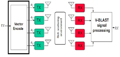
[image:1.595.327.533.367.464.2]Ultimate goals of the future generation wireless communication system are high data rate, high-performance and optimum utilization of the bandwidth. MIMO wireless systems help to achieve that goal. MIMO systems establish an arbitrary wireless communication a link for which the transmitting end as well as the receiving end is equipped with multiple antenna elements as illustrated in Fig. 1.
Fig 1: A model of V Blast System
International Journal of Emerging Technology and Advanced Engineering
Website: www.ijetae.com (ISSN 2250-2459, ISO 9001:2008 Certified Journal, Volume 3, Issue 5, May 2013)
401
In Section II, the system model is described. In Section III, describe the functionality of proposed methodology MMSE-IC and Matched Filter in AWGN channel. In Section IV describe the detection algorithm used in MIMO System. The simulation results and conclusion are provided in Section V and Section VI, respectively.
II. SYSTEM MODEL
V Blast Architecture:
BLAST stands for Bell Laboratories Layered Space Time and V stands for Vertical which relates to the blocking structure. V-BLAST is a wireless communication technique which uses multi-element antennas at both transmitter and receiver. It is an extra ordinarily bandwidth efficient approach for wireless networks. Its spectral efficiency ranges from 20 to 40 bps/Hz while efficiency of traditional wireless communication techniques ranges from 1 to 5 bps/Hz (mobile cellular) to around 10 to 12 bps/Hz (point to point fixed microwave system)[6]. For a V-BLAST system with Nttransmit antennas and Nrreceive antennas
(Nr≥ Nt), a single data stream is split in to Nt parallel
sub-streams and each sub-stream is sent through a corresponding transmit antenna.
[image:2.595.65.267.472.583.2]The V-BLAST high-level block diagram is illustrated in Fig.2 the received vector with size nR1 is modelled by [7].
Fig 2: V-BLAST high-level block diagram
r = H a + n (1)
Where H represents the channel matrix with dimension nR nT whose element hij, represents the complex fading coefficient for the path from transmit j to receive antenna i. These fading coefficients are modelled by an independent zero mean complex Gaussian random variable with variance 0.5 per dimension. A denotes the vector of transmitted symbols with dimension nT 1, n represents a complex vector of independent samples of AWGN over each received antenna with zero mean and variance .
G = (H+ H)-1 H+ (2)
(3)
MIMO System:
Multiple Input Multiple Output (MIMO) systems have recently emerged as a key technology in wireless communication systems for increasing both data rates and system performance. Techniques that use arrays of multiple transmit and receive antennas may offer high capacity to present and future wireless communications systems, which place severe demands on current spectral resources. Multiple-input Multiple-output (MIMO) systems provide for a linear increase of capacity with the number of antenna elements. Multiple antennas used in both the transmitter and receiver sides of a communication link, termed Multiple Input Multiple Output (MIMO) scheme, play a role in increasing the system capacity to an enormous amount as well as handling multipath fading problem.
Techniques used to exploit the high-capacity nature of a MIMO system include Layered Space-Time architectures, namely Diagonal Bell Laboratories Layered Space-Time (DBLAST) and Vertical Bell Laboratories Layered Space-Time (V-BLAST).
III. PROPOSED METHODOLOGY
V-BLAST MMSE IC algorithm is shown in figure 3 by this block diagram in which N no. of signals are transmitted through N no. of Transmitters. Information is received by N no. of receiver at the receiving side.
This V-BLAST diagram shows a performance of system in Rayleigh fading environment by using Matched Filter therefore BER will be decreased and system performance will increase as our system will proceed.
So, this will provide high system performance by Matched Filter in Fading Diversity Environment in MIMO configuration.
Fig 3: Proposed MIMO based V-BLAST system
IV. DETECTION ALGORITHM
[image:2.595.316.553.554.631.2]International Journal of Emerging Technology and Advanced Engineering
Website: www.ijetae.com (ISSN 2250-2459, ISO 9001:2008 Certified Journal, Volume 3, Issue 5, May 2013)
402
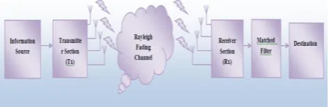
[image:3.595.57.266.295.373.2]The transmitter consists of a binary random generator, a QPSK baseband modulator and a vector encoder. The binary random generator generates the transmitted bits. These bits are modulated in the QPSK modulator using the complex envelope form. It is assumed that each symbol has an ideal rectangular pulse shape and may be sampled with a single point per symbol. The vector encoder maps the symbols to each antenna. In the channel block, the transmitted symbols undergo Rayleigh fading and additive noise. Rayleigh fading channel coefficients are generated with two independent Gaussian random variables with unit variance. Fig.4 describes simulation block diagram for V-BLAST scheme.
Fig 4: Simulation block diagram for V-BLAST
The phase delay is distributed uniformly. In addition, the channel is assumed to be quasi-stationary, that is, the channel coefficients do not vary during the given period time. The receiver is made up of decoding processing and an error rate calculation block. At the decoding processing block, we simulate the several types of schemes reviewed briefly in analysis section. The decoding methods are reviewed in the following section. PIC does not need to consider the ordering issue. We compare the performance for ordered and non-ordered systems, and the simple ZF and MMSE technique are compared on the basis of PIC and SIC algorithm. For applying the MMSE technique, we need to know the SNR at the receiver. Therefore, knowledge of the SNR is also assumed at the receiver. Finally the SER is calculated by comparing the originally transmitted symbols with received symbols that are estimated at the receiver.
V. SIMULATION RESULTS
In our Simulation result we have compared our proposed methodology with three different environments that is relay fading environment, frequency selective relay fading environment& fading diversity. All the Simulation performed on various configurations of transmitter &receiver because it is a MIMO system. In v-blast MIMO MMSE-IC system perform differently in different environments. Here we have considered relay fading environment for simulation &it’s other type. The performance of proposed system is better in fading diversity but if we use matched filter in existing system.
The performance also vary where we used different no of transmitter & receiver configuration.
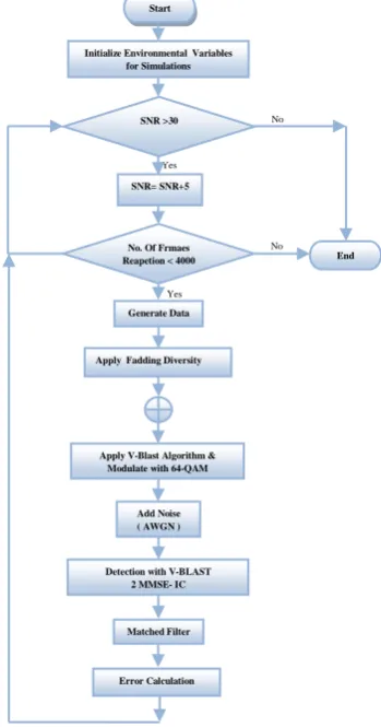
A procedure & execution of proposed work on Matlab simulation tool is describe with the help of flow chart given below. In the flow chart the V-BLAST Algorithm is used for MIMO configuration for increasing the system performance MMSE IC and modulation scheme (64- QAM). In the diagram firstly some environmental variables are initialized for simulation after that value of SNR will be tested up to 30 dB(SNR≤30dB) if SNR Less than 30dB then simulation process is reached to end but if SNR greater than 30dB then in the next step SNR will be increased by 5dB. After this no. of frames are tested (Frames≤ 4000 times). If frames are greater than set time period then this goes back to previous stage (SNR≤30dB) and if frames are less than set time period then it goes to the next stage there Data is generated and then apply fading diversity with V-BLAST algorithm and Modulator with 64 QAM after this Noise(AWGN) is added there after V-BLAST MMSE IC detects the signal with Matched filter and in the last the BER is calculated till 4000 times frame repetition.
Fig 5: Flow Chart of Proposed Methodology No No
Yes
Yes
SNR= SNR+5
Apply V-Blast Algorithm & Modulate with 64-QAM
Add Noise ( AWGN ) Detection with V-BLAST
2 MMSE- IC Matched Filter Error Calculation
No. Of Frmaes Reapetion < 4000
Apply Fadding Diversity Generate Data
End Initialize Environmental Variables
for Simulations Start
[image:3.595.354.529.397.730.2]International Journal of Emerging Technology and Advanced Engineering
Website: www.ijetae.com (ISSN 2250-2459, ISO 9001:2008 Certified Journal, Volume 3, Issue 5, May 2013)
403
Below Simulation result are performed on 2x2, 3x3, 4x4, 5x5, 6x6, 7x7, 8x8, & 9x9. Transmitter and receiver system and signal to noise ratio from 0 to 35 db.
0 5 10 15 20 25 30 35
10-5
10-4
10-3
10-2
10-1
100 Performance of V-Blast MMSE-IC MIMO System with 2 x 2 Transmitter Configuration
SNR(dB)
Bi
t
Er
ro
r
R
a
te
in Rayleigh Fading Environment in Frequency Selective Rayleigh Fading Environment in Fading Diversity Environment
[image:4.595.73.269.179.324.2]in Fading Diversity Environment using Matched Filter
Fig 5.1: Performance Comparison of V-Blast MIMO MMSE IC
System in Different Fadding Environments for 2x2 Tx & Rx configuration
In this fig 5.1 shown a performance comparsion of V-BLAST MIMO MMSC-IC system in different fading enviorement for 2x2 transmitter &receiver configuration . in fig we have seen that a great performance of V-BLAST MMSC-IC system using matched filter by which bit error rate is redued in system and &performance will increase . which is shown by red characteristics in result. Transmitter and receiver system and signal to noise ratio from 0 to 35 db.
0 5 10 15 20 25 30 35
10-4 10-3 10-2 10-1 100
Performance of V-Blast MMSE-IC MIMO System with 3 x 3 Transmitter Configuration
SNR(dB)
Bi
t
Er
ro
r
R
a
te
in Rayleigh Fading Environment
in Frequency Selective Rayleigh Fading Environment in Fading Diversity Environment
[image:4.595.330.519.226.380.2]in Fading Diversity Environment using Matched Filter
Fig 5.2: Performance Comparison of V-Blast MIMO MMSE IC System in Different Fadding Environments for 3x3 Tx & Rx
configuration
In this fig 5.2 shown a performance comparsion of V-BLAST MIMO MMSC-IC system in different fading enviorement for 3x3 transmitter &receiver configuration.
In fig we have seen that a great performance of V-BLAST MMSC-IC system using matched filter by which bit error rate is redued in system and &performance will increase . which is shown by red characteristics in result.
Transmitter and receiver system and signal to noise ratio from 0 to 35 db.
0 5 10 15 20 25 30 35
10-4 10-3
10-2
10-1
100 Performance of V-Blast MMSE-IC MIMO System with 4 x 4 Transmitter Configuration
SNR(dB)
Bi
t
Er
ro
r
R
a
te
in Rayleigh Fading Environment in Frequency Selective Rayleigh Fading Environment in Fading Diversity Environment
[image:4.595.55.262.483.646.2]in Fading Diversity Environment using Matched Filter
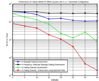
Fig 5.3: Performance Comparison of V-Blast MIMO MMSE IC System in Different Fadding Environments for 4x4 Tx & Rx
configuration
In this fig 5.3 shown a performance comparsion of V-BLAST MIMO MMSC-IC system in different fading enviorement for 4x4 transmitter &receiver configuration. in fig we have seen that a great performance of V-BLAST MMSC-IC system using matched filter by which bit error rate is redued in system and &performance will increase . which is shown by red characteristics in result. Transmitter and receiver system and signal to noise ratio from 0 to 35 db
0 5 10 15 20 25 30 35
10-6 10-5
10-4 10-3 10-2
10-1
100
Performance of V-Blast MMSE-IC MIMO System with 5 x 5 Transmitter Configuration
SNR(dB)
Bi
t
Er
ro
r
R
a
te
in Rayleigh Fading Environment
in Frequency Selective Rayleigh Fading Environment in Fading Diversity Environment
in Fading Diversity Environment using Matched Filter
Fig 5.4: Performance Comparison of V-Blast MIMO MMSE IC System in Different Fadding Environments for 5x5 Tx & Rx
[image:4.595.329.540.537.702.2]International Journal of Emerging Technology and Advanced Engineering
Website: www.ijetae.com (ISSN 2250-2459, ISO 9001:2008 Certified Journal, Volume 3, Issue 5, May 2013)
404
In this fig 5.4 shown a performance comparsion of V-BLAST MIMO MMSC-IC system in different fading enviorement for 5x5 transmitter &receiver configuration . in fig we have seen that a great performance of V-BLAST MMSC-IC system using matched filter by which bit error rate is redued in system and &performance will increase. which is shown by red characteristics in result. Transmitter and receiver system and signal to noise ratio from 0 to 35 db.
0 5 10 15 20 25 30 35
10-5
10-4 10-3
10-2 10-1
100 Performance of V-Blast MMSE-IC MIMO System with 6 x 6 Transmitter Configuration
SNR(dB)
Bi
t
Er
ro
r
R
a
te
in Rayleigh Fading Environment
in Frequency Selective Rayleigh Fading Environment in Fading Diversity Environment
in Fading Diversity Environment using Matched Filter
Fig 5.5: Performance Comparison of V-Blast MIMO MMSE
IC System in Different Fadding Environments for 6x6 Tx & Rxconfiguration
In this fig 5.5shown a performance comparsion of V-BLAST MIMO MMSC-IC system in different fading enviorement for 6x6 transmitter &receiver configuration . in fig we have seen that a great performance of V-BLAST MMSC-IC system using matched filter by which bit error rate is redued in system and &performance will increase which is shown by red characteristics in result. Transmitter and receiver system and signal to noise ratio from 0 to 35 db
0 5 10 15 20 25 30 35
10-4
10-3
10-2
10-1
100
Performance of V-Blast MMSE-IC MIMO System with 7 x 7 Transmitter Configuration
SNR(dB)
Bi
t
Er
ro
r
R
a
te
in Rayleigh Fading Environment
in Frequency Selective Rayleigh Fading Environment in Fading Diversity Environment
[image:5.595.330.533.244.410.2]in Fading Diversity Environment using Matched Filter
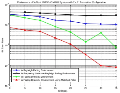
Fig 5.6: Performance Comparison of V-Blast MIMO MMSE IC System in Different Fadding Environments for 7x7 Tx & Rx
configuration
In this fig 5.6 shown a performance comparsion of V-BLAST MIMO MMSC-IC system in different fading enviorement for 3x3 transmitter &receiver configuration . in fig we have seen that a great performance of V-BLAST MMSC-IC system using matched filter by which bit error rate is redued in system and &performance will increase which is shown by red characteristics in result. Transmitter and receiver system and signal to noise ratio from 0 to 35 db.
0 5 10 15 20 25 30 35
10-4
10-3 10-2 10-1
100 Performance of V-Blast MMSE-IC MIMO System with 8 x 8 Transmitter Configuration
SNR(dB)
Bi
t
Er
ro
r
R
a
te
in Rayleigh Fading Environment
in Frequency Selective Rayleigh Fading Environment in Fading Diversity Environment
[image:5.595.54.273.245.411.2]in Fading Diversity Environment using Matched Filter
Fig 5.7: Performance Comparison of V-Blast MIMO MMSE IC
System in Different Fadding Environments for 8x8 Tx & Rx configuration
In this fig 5.7 shown a performance comparsion of V-BLAST MIMO MMSC-IC system in different fading enviorement for 3x3 transmitter &receiver configuration . in fig we have seen that a great performance of V-BLAST MMSC-IC system using matched filter by which bit error rate is redued in system and &performance will increase . which is shown by red characteristics in result. Transmitter and receiver system and signal to noise ratio from 0 to 35 db.
0 5 10 15 20 25 30 35
10-4
10-3 10-2 10-1
100 Performance of V-Blast MMSE-IC MIMO System with 9 x 9 Transmitter Configuration
SNR(dB)
Bi
t
Er
ro
r
R
a
te
in Rayleigh Fading Environment
in Frequency Selective Rayleigh Fading Environment in Fading Diversity Environment
[image:5.595.65.261.566.718.2]in Fading Diversity Environment using Matched Filter
Fig 5.8: Performance Comparison of V-Blast MIMO MMSE IC System in Different Fadding Environments for 9x9 Tx & Rx
International Journal of Emerging Technology and Advanced Engineering
Website: www.ijetae.com (ISSN 2250-2459, ISO 9001:2008 Certified Journal, Volume 3, Issue 5, May 2013)
405
In this fig 5.8 shown a performance comparsion of V-BLAST MIMO MMSC-IC system in different fading enviorement for 3x3 transmitter &receiver configuration . in fig we have seen that a great performance of V-BLAST MMSC-IC system using matched filter by which bit error rate is redued in system and &performance will increase. Which is shown by red characteristics in result. Transmitter and receiver system and signal to noise ratio from 0 to 35 db.
VI. CONCLUSION
In this paper, a new detection algorithm with MMSE-IC is proposed for the V-BLAST System which can be achieved by the Matched Filter. As it is shown in the simulation results and the complexity as well as bit error rate reduced by our approach in MIMO configuration. Moreover we can achieve different trade off between Relay fading environment, in frequency selective Relay Fading environment, in fading Diversity and fading diversity environment using Matched Filter.
REFERENCES
[1 ] I.E. Telatar, .Capacity of multi-antenna Gaussian channels,
European Transactions on Telecommunications, vol. 10, no.6, pp.585-595, November/December 1999.
[2 ] A.Paulraj and R.J.Heath, .Characterization of MIMO Channels for
Spatial Multiplexing Systems. IEEE International Conference on Communications, vol.2, no.11-14,pp-591-595,June 2001.
[3 ] G. J. Foschini and M. J. Gans, “On limits of wireless
communications in fading environments when using multiple antennas,” Wireless Pers.Commun., vol. 6, pp. 311–335, 1998.
[4 ] J. H. Winters, “On the capacity of radio communications
systemswith diversity in rayleigh fading environments,” IEEE J. Select. Areas Commun., vol. JSAC-5, pp. 871–878, June 1987.
[5 ] Branka Vucetic, Jinhong Yuan, “Space-Time Coding”, John
Wiley & Sons Ltd, 2003.
[6 ] www.bell_labs.com/research/wireless2.html#bt.
[7 ] P.W. Wolniansky, GJ. Foschini, G.D. Golden and R.A.Valenzuela, "VBLAST: An Architecture for RealizingVery High Data Rates Over the Rich-Scattering Wireless Channef', Proc. URSI ISSSE, Italy, 1998, Pp.295-300.
[8 ] G. J. Foschini: “Layered space-time architecture for wireless
communication in fading environments when using multiple antennas,” Bell Labs Technical Journal, vol. 1, no.2, pp. 41- 59, Autumn 1996.
[9 ] W.J. Choi, R Negi, and J.M. Cioffi, “Combined ML and DFE
decoding for the V-BLAST system,” in IEEE Int. Conf. on Communications, vol. 3, pp.1243-1248, 2000.
[10 ]G. J .Foschini, G. D. Golden, R. A. Valenzuela, and P. W.
Wolniansky, “Simplified processing for high spectral efficiency wireless communication employing multi-element arrays,” IEEE Journal on Selected Areas in Communications, vol. 17, pp.1841-1852,Nov. 1999.
[11 ]M. Sellathurai and S. Haykin, “Turbo-BLAST: performance