International Journal of Emerging Technology and Advanced Engineering
Website: www.ijetae.com (ISSN 2250-2459,ISO 9001:2008 Certified Journal, Volume 4, Issue 7, July 2014)
155
Parametric Study of Centrifugal Pump and its Performance
Analysis using CFD
Shardul Sunil Kulkarni
11
Rajarambapu Institute of Technology, Rajaramnagar-415414, Maharashtra, India
Abstract— A wide variety of centrifugal pump types have
been constructed and used in many different applications in industry and other technical sectors. Their design and performance prediction process is still a difficult task, mainly due to the great number of free geometric parameters, the effect of which cannot be directly evaluated. The significant cost and time of the trial-and-error process by constructing and testing physical prototypes is always undesirable and can be avoided by using advanced techniques. For this reason CFD analysis is currently being used in the design and construction stage of various pump types, the use of which reduces significantly the new pump development time and costs. The numerical simulation can provide quite accurate information on the fluid behavior in the machine, and thus helps the engineer to obtain a thorough performance evaluation of a particular design. CFD study predicts the performance of pump impellers and helps us rapidly to establish the efficiency of the pump over various operating conditions.
Keywords— Centrifugal Pump, Centrifugal Impeller, Performance Curves, Creo 2.0, ANSYS CFX, CFD.
I. INTRODUCTION
Centrifugal pump is a machine that imparts energy to a fluid. This energy can cause a liquid to flow or rise to a
higher level. Centrifugal pump is an extremely simple
machine which consists of two basic parts: The rotary
element or impeller and the stationary element or casing.
The centrifugal pumps are widely used in the world
because the pump is robust, effective and inexpensive to
produce. Centrifugal pumps are more economical to own,
operate and maintain than other types of pumps. Pumps
operate via many energy sources, including manual operation, electricity, engines, or wind power, come in many sizes, from microscopic for use in medical applications to large industrial pumps. Mechanical pumps serve in a wide range of applications such as pumping water from wells, aquarium filtering, pond filtering and aeration, in the car industry for water-cooling and fuel injection etc. Various terminologies for centrifugal pump are as follows:
Head: The word ―Head‖ is frequently spoken in the field of water works, pumping, etc.
Fig. 1
A column of water or any liquid in a vertical pipe exerts certain pressure on horizontal surface at the bottom, this
pressure is expressed in kg/cm2 or metres of liquid column.
The height of the liquid column is known as HEAD.
Pump Performance Curves:
Centrifugal pump design is a highly developed field, with much known about pump theory and design procedures. However, due to the general complexity of flow through a centrifugal pump, the actual performance of the pump cannot be accurately predicted on a completely theoretical basis. Actual pump performance is determined experimentally through tests on the pump. From these tests, pump characteristics are determined and presented as pump
performance curves. Performance characteristics for a
given pump geometry and operating speed are usually given in the form of plots of ha, η and BHP (Brake Horse Power) versus Q (Capacity). The head curve continuously
rises as the flow rate decreases, andin this case the pump is
said to have a rising head curve. Pumps may also have ha - Q curves that initially rise as Q is decreased from the design value and then fall with a continued decrease in Q. These pumps have a falling head curve. The head developed by the pump at zero discharge is called the shutoff head, and it represents the rise in pressure head across the pump with the discharge valve closed. Since there is no flow with the valve closed, the related efficiency
is zero, and the power supplied by the pump
International Journal of Emerging Technology and Advanced Engineering
Website: www.ijetae.com (ISSN 2250-2459,ISO 9001:2008 Certified Journal, Volume 4, Issue 7, July 2014)
156
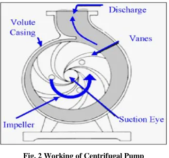
Working of Centrifugal Pumps [2,3,12]
[image:2.612.82.256.200.363.2]A Centrifugal Pump is a machine which converts mechanical energy into hydraulic energy. It consists of a set of rotating vanes enclosed within a casing to impart energy to the fluid through centrifugal force.
Fig. 2 Working of Centrifugal Pump
Liquid is forced into an impeller either by atmospheric pressure or in case of a jet pumps by artificial pressure. The vanes of impeller pass kinetic energy to the liquid, thereby causing the liquid to rotate. The liquid leaves the impeller at high velocity. The impeller is surrounded by a volute. The volute converts the kinetic energy into pressure energy.
II. USE OF COMPUTATIONAL FLUID DYNAMICS (CFD)
The direct flow analysis in hydraulic turbo machines using Computational Fluid Dynamic (CFD) methods can provide a quite illuminating picture of the developed flow field and its detailed characteristics. A numerical model for the simulation of the 3-dimensional turbulent flow in centrifugal pump impellers can be developed in, solving the Reynolds Averaged Navier Stokes equations with the control volume approach and on Cartesian grids. The computations for the steady flow field in a particular impeller can be presented and analyzed. The impeller geometry is represented by a number of controllable design variables, providing the capability of modifying the impeller shape and testing different configurations. This technique, combined with grid generation algorithm facilitates the investigation and assessment of the effects of impeller design on its hydrodynamic behavior. The results of such parametric studies conducted shows that a remarkable gain in hydraulic efficiency may be achieved
by optimizing the impeller geometry.
As the CFD analysis can be carried out on prototype also, the issues related to in-accurate prediction of prototype flows from model studies using smaller size experimental models do not come into picture. CFD tools avoid physical modelling and testing every time. The data generated in the CFD analysis of the pump can be kept for future reference and use also.
CFD analysis can be used to see parts of the system or phenomena happening within the system that would not otherwise be visible through experimental analysis. CFD gives a means of visualizing and enhanced understanding of the fluid flow and hence better insight of the flow in the pump.
III. DESIGN OF CENTRIFUGAL PUMP
There is no rigorous procedure to be followed in designing a pump. Each company has developed its own approach and, although each has a slightly different method of calculation, the broad underlying principles of all are similar. The various companies have velocity limitations and proportions to which they attempt to adhere, but these may be exceeded in certain instances to meet competition with regard to cost or performance.
A. Input Data
Customer has given certain input parameters according to their requirements. These requirements are as follows,
Required head : H = 475m
Required flow rate : Q = 2135m3/hr
Required speed : N = 4200 rpm
Motor Rating : 4.5MW
B. Shaft Diameter Calculations [5,6]
6 60*10 *
2 shaft
BHP KW
T
N N
,
6 3
60*10 * 2.87 *10 2 * 4200 shaft
T
, 6525352.667
shaft
T Nmm
For shaft material F6NM (ASTM A182), the Yield
strength is Syt = 620MPa, so, according to maximum shear
stress theory,
0.5*
sy yt
S S
,
sy
s
S
f
,
310
4
,
77.5N mm/ 2316 316*6525352.667 *77.5 shaft
s
T D
International Journal of Emerging Technology and Advanced Engineering
Website: www.ijetae.com (ISSN 2250-2459,ISO 9001:2008 Certified Journal, Volume 4, Issue 7, July 2014)
157
1.5
H S
D D , DH1.5*76, DH114mm
After calculating the minimum shaft diameter and for that all impeller dimensions, different dimensions of stepped shaft have been finalized. The stepped shaft is designed on the basis of fitment of standard parts on shaft like; wear rings, throat bush, shaft sleeve, bearings and bearing housings, etc.
C. Impeller Design[2.6.8]
First we will calculate for diameter of suction flange and eye diameter of impeller,
*
QA V,
2 *
4 SU SU
Q D V
, 4 SU SU Q D V ,
4 * 20.6804 *144 * 20 SU
D
, DSU350mm13.79inch
For a double suction pump, consider that the leakage will not exceed 2%., hence dividing the total flow by 2,
2 2
0
0 0 0( )
4 4
H
D D
QV A V
,
2 0
0
(4)(1.02)
( )(2) H
Q D D V , 2 0 4*1.02* 20.6804*144 4.4916 * 2* 20
D
,
0
275
10.835
[image:3.612.386.500.134.224.2]D
mm
inch
Fig. 3 Impeller Specifications
Now for impeller inlet dimensions and angle,
Taking an inlet diameter, D1=10.835 inch. Therefore,
tangential velocity of inlet vane edge is given by,
1 1 1
2 60* 2*12
ND U r
, 1
4200* 2* *10.835 60* 2*12
U
, U1198.5617ft s/
Fig. 4 Inlet Velocity Triangles [6]
The radial velocity should be slightly higher than V0
because a converging shape is more efficient than a divergent one. Let Vr1 be 25 ft/s.
1 1 1
1
tan Vr
U , 1 0 1 25 tan 7.18 198.5617
1 is usually increased slightly to account for contraction
of the stream as it passes the inlet edges as well as pre rotation. For better performance, A. H. Church says that the inlet angle should be between 100 to 250, hence taking
1 = 11
0 .
1 1tan 1
r
V U , Vr138.5965ft s/
Now for impeller diameter, D2,
2 2 2 1 2 1 2 1
2
P P U U
H H g g , As P H g
The pressure head developed at the outer rim is,
2 2 2 2 U H g
Substituting D2 ×/2 for U2 and solving for D2,
2 2
2 2gH
D , 2 2
2 (2)(32.2) *60*12
2* * H D N , 2 2 1840 H D N
By the tests we suppose to think the head coefficient in
this. D H N 2 1840
[image:3.612.50.283.380.571.2]International Journal of Emerging Technology and Advanced Engineering
Website: www.ijetae.com (ISSN 2250-2459,ISO 9001:2008 Certified Journal, Volume 4, Issue 7, July 2014)
158
Now for outlet impeller dimensions,
For the better efficiency of pump, the range for outlet vane angle is 200 to 250. Therefore taking β2 = 210. Also
Church says that, the radial velocity, Vr2 is made the same
as or slightly less than the radial inlet velocity Vr1. Hence taking Vr2 = 35ft/s.
2
2 2
2 60* 2
ND U r
[image:4.612.366.526.133.243.2], U2321.309ft s/
Fig. 5 Outlet Velocity Triangle
Now, theoretical tangential outlet velocity is,
2
2 2
2
tan
r
V
V U
, V2230.1309ft s/
Circular flow coefficient can be calculated as,
,
2 2 1 2 1
0.75 21 2
1 1
5 60 1 13.75 / 22.25
, 0.6041
Therefore, actual tangential velocity at outlet is given by,
'
2 * 2
V V , '
2 0.6041*230.1309
V , '
2 139.0326 /
V ft s
' 1 2
2 '
2
tan Vr
V
,
' 2 '
2 r2 2
V V V
, V’2 = 143.37ft/s.
Hence the design of the centrifugal impeller is done.
IV. CFDANALYSIS OF THE CENTRIFUGAL PUMP
Depending upon the calculated parameters the modelling of the pump components is done in PTC Creo 2.0 and then the CFD analysis of the centrifugal pump is performed.
Fig. 6 3D Model of Impeller
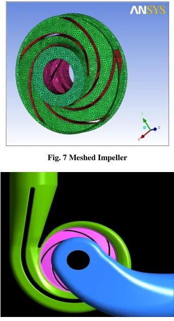
[image:4.612.49.260.216.359.2]For performing CFD analysis meshing is done in ICEM CFD software tool. During meshing there is one important point and that is, model should be imported as a surface model. And then volume meshing is done over that.
Fig. 7 Meshed Impeller
[image:4.612.357.530.300.620.2]International Journal of Emerging Technology and Advanced Engineering
Website: www.ijetae.com (ISSN 2250-2459,ISO 9001:2008 Certified Journal, Volume 4, Issue 7, July 2014)
159 Fig. 9 Surface Grid plot of pump geometry
After meshing, boundary conditions are applied and they are as follows:
Inlet Pressure = Booster Pump Pressure at Inlet of Main Pump + Water Pressure at Inlet
= 8.025bar + 6.5bar = 14.52bar
• Mass Flow Rate = 2135m3/hr
• Impeller angular Speed = 4200rpm
• Working Temperature = 1580 C
• Density = 909Kg/m3
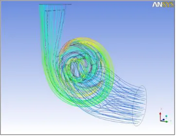
[image:5.612.336.533.124.497.2]By applying the boundary conditions, the solver is allowed to solve the problem with 1000 iterations. At the end of iterations, the solution is done. Then the result file is imported in the CFX-Post and the results are obtained. The streamline flow in the casing of the pump is shown in the fig. 10 below,
[image:5.612.80.256.130.276.2]Fig. 10 Whole Streamline Flow
Fig. 11 Streamline Flow in Impeller
Fig. 12 Head Produced by Pump
The head produced is calculated as,
H = [(P1-P2)/ (ρ×g)] – Booster Pump Head
H = [(61.7E5 – 11.21E5)/ (909×9.81)] – 90
H = 476.203 m.
V. RESULTS
[image:5.612.78.259.515.657.2]International Journal of Emerging Technology and Advanced Engineering
Website: www.ijetae.com (ISSN 2250-2459,ISO 9001:2008 Certified Journal, Volume 4, Issue 7, July 2014)
[image:6.612.50.293.157.534.2]160 Table 1.
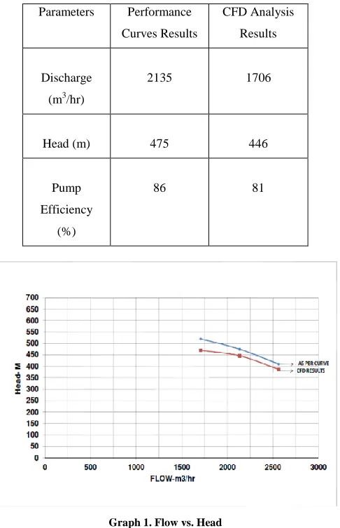
Results by Curve and CFD
Parameters Performance
Curves Results
CFD Analysis
Results
Discharge
(m3/hr)
2135 1706
Head (m) 475 446
Pump
Efficiency
(%)
86 81
Graph 1. Flow vs. Head
Graph 1 shows variation of centrifugal pump head with increase in discharge. It was found that the head predicted by CFD analysis was 5 to 7 % lower than the mode test results. Graph 2 shows variation of pump efficiency with
increase in discharge.It is seen that as discharge increases,
the efficiency increases, and reaches maximum at rated conditions and then decreases when discharge increases beyond rated conditions, i.e. it has parabolic profile.
Graph 2. Flow vs. Pump Efficiency
VI. CONCLUSION AND FUTURE SCOPE
The design and analysis of the centrifugal pump is done and through analysis we conclude that the deflection on the vane of an impeller is very less and within the design limits and hence the design of the impeller is safe. The shaft is designed and the deflection of the shaft is less and within design limits. The CFD analysis of the centrifugal pump is done for determining the performance of centrifugal pump at particular temperature and pressure as per the requirement. The theoretical results are compared with the CFD results and hence we can say that the quantitative results match with the required results. The variation in the CFD result is due to the surface finish factor which plays a very vital role in determining the efficiency of the centrifugal pump. By CFD analysis, the efficiency obtained is 81 % which is satisfactory.
The efficiency of the centrifugal pump can be improved
by increasing the value of surface finish factor. The
International Journal of Emerging Technology and Advanced Engineering
Website: www.ijetae.com (ISSN 2250-2459,ISO 9001:2008 Certified Journal, Volume 4, Issue 7, July 2014)
161
REFERENCES
[1 ] Pramod J. Bachche1, R.M.Tayade, ―Finite Element Analysis of Shaft of Centrifugal Pump‖, IOSR Journal, Volume 7, Issue 3, Aug-2013.
[2 ] Khin Cho Thin, ―Design and Performance Analysis of Centrifugal Pump‖, World Academy of Science, Engineering and Technology 22 2008, PP. 424-432.
[3 ] S.R.Shah and S.V.Jain, ―CFD for Centrifugal Pumps‖, Chemical, Civil and Mechanical Engineering Tracks of 3rd Nirma University International Conference (NUiCONE 2012), PP. 135-140.
[4 ] W.K. Chan, ―The flow patterns within the impeller passages of a centrifugal blood pump model‖, Medical Engineering & Physics 22 (2000), PP. 381–393.
[5 ] ―Design of Shaft‖, Shaft and its design based on strength, module 8, lesson 1, Version 2 ME, IIT Kharagpur.
[6 ] Austin H Church, ―Centrifugal pumps and blowers‖, John Willey & son’s publication, 1st edition, 1944.
[7 ] John S. Anagnostopoulos, ―CFD analysis and design effects in a radial pump impeller‖, Wseas transactions on fluid mechanics, Issue-7, Vol.-1, july 2006.
[8 ] A Shyam Prasad, BVVV Lakshmipathi Rao, A Babji, Dr P Kumar Babu, ―Static and Dynamic Analysis of a Centrifugal Pump Impeller‖, IJSER, Volume 4, Issue 10, Oct-2013.
[9 ] Karan Rajdev, ―Pressure and stress distribution analysis of centrifugal pump‖, Thapar University, Patiyala, June 2008. [10 ]Mario Savar and Hrvoje Kozmar, ―Improving centrifugal pump
efficiency by impeller trimming‖, Desalination 249 (2009), PP. 654– 659.
[11 ]Ramesh Agarwal and Ling Zhou, ―Numerical and Experimental Study of Axial Force and Hydraulic Performance in a Deep-Well Centrifugal Pump with Different Impeller Rear Shroud Radius‖, Fluids Engineering Division of ASME OCTOBER 2013, Vol. 135, PP. 654-670.
![Fig. 4 Inlet Velocity Triangles [6]](https://thumb-us.123doks.com/thumbv2/123dok_us/8711392.882002/3.612.386.500.134.224/fig-inlet-velocity-triangles.webp)