International Journal of Emerging Technology and Advanced Engineering
Website: www.ijetae.com (ISSN 2250-2459,ISO 9001:2008 Certified Journal, Volume 5, Issue 4, April 2015)
561
Firefly Algorithm Based Approach for Stability Enhancement
in Interconnected Power System Using PSS
P. Sarmila Devi
1, S. Bharath
21
PG Scholar, Dept of EEE, SNSCT, Coimbatore, India
2Assistant Professor, Dept of EEE, SNSCT, Coimbatore, India
Abstract-One of the most important characteristics of power systems as it is maintaining their power system stability when subjected to the disturbances. Power System Stabilizers (PSSs) are the most used devices to damp Low Frequency Oscillations (LFO) and increase the system dynamic stability due to their flexibility, easy implementation and minimum cost. In this paper presents a technique for designing PSS to improve damping of low frequency oscillations under dynamic disturbances. This problem is formulated as a multi-objective optimization problem with the aim of tuning the PSS parameters in the case of non-linear time domain simulation. The Firefly Algorithm (FFA) which has been found robust in solving these kinds of optimization problems is selected as a tool to determine the optimum solution. Results obtained from this method are presented and compared with the Particle Swarm Optimization (PSO) method. Simulations are executed on the two area four machine (TAFM) system under fault conditions. The simulation of the proposed model was carried out by using MATLAB.
Keywords- Power System Stabilizer; Low frequency oscillations; Firefly Algorithm; Particle Swarm Optimization
I. INTRODUCTION
The power system stabilizer (PSS) is a primary control of a generator‟s excitation system. The output signal of the PSS is given to the summing junction of the exciter block in the generator to damp out low frequency oscillations of the system. It is the most economical way to recover these kinds of low frequency oscillations. In order for the PSS to perform its work, it is very important to optimally tune the parameters of the PSS, which are composed of lead-lag time constants, washout time constant and a gain.
The parameter tuning of the PSS and its application have been studied and applied to power systems around the world since the 1960s. The reasons for tuning PSS parameters are to compensate for the phase lag due to provide electrical torque is in-phase with the rotor speed via the excitation system and generator. However, the difficulties of parameter tuning the PSS and applying them to the power system, derived from the complexity of the interconnected power system and the wide range of operating points, have made authorities reluctant to use PSS.
In spite of these complexities, excellent PSS tuning guides for single-input PSS have been recommended and double input PSS have been reported as an alternative for successful operation. The double-input PSS, which uses power and frequency as an input, has many merits over a single-input PSS, such as the speed-input PSS or power input PSS. This is because double-input PSS delivered a damping torque for the power system on a large range of frequencies of concern and is less sensitive to shaft torsional oscillation.
In multi-machine systems with several poorly damped modes of power system oscillations, several power system stabilizers (PSS) need to be on-line and optimally tuned. With present-day large-scale systems comprising many interconnected machines, the problem of PSS tuning is not a straight-forward method, and in some situation can become relatively too tedious to resolve. The problem of PSS parameter tuning is further complicated by the fact that operating conditions in a power system are continuously changing. Therefore parameter tuning the PSS such that, it would give a satisfactory role over the entire range of variations is a rather exhaustive exercise. Research has been directed towards the design of adaptive (self-tuning), variable structure and other control methods that provide robust tuning of PSS parameter. However, the implementation of such PSS needs continuous on-line calculation of an identified model using parameter determination and evaluates the control strategy. In recent years, research has been directed towards the application of advanced numerical computation techniques such as neural networks and Genetic Algorithms (GA), Particle Swarm Optimization (PSO), Firefly Algorithm (FFA) to PSS parameters tuning.
International Journal of Emerging Technology and Advanced Engineering
Website: www.ijetae.com (ISSN 2250-2459,ISO 9001:2008 Certified Journal, Volume 5, Issue 4, April 2015)
562
Performance of the proposed algorithm is examined through nonlinear time-domain simulations. Finally, results are compared with PSO-based PSS to illustrate the superiority of the proposed algorithm.II. POWER SYSTEM MODELLING
A. Two Area Four Machine System
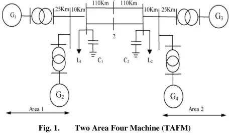
[image:2.612.54.282.317.451.2]Kundur‟s Two Area Four Machine (TAFM) system consisting of two fully symmetrical areas interconnected by two 220 km, 230 kV transmission lines is considered as a test system in this paper [1]. This test system typically is used to study the low frequency electromechanical oscillations of a large interconnected system. Figure 1 shows the Two Area Four Machine (TAFM) system.
Fig. 1. Two Area Four Machine (TAFM)
B. Power System Stabilizer
[image:2.612.66.279.600.696.2]The primary purpose of a power system stabilizer (PSS) is to extend the rotor angle stability of a power system and considered an effective means for damping the power system oscillation. This is basically performed by providing supplemental damping to the oscillation of rotors of synchronous machines that is in phase with the rotor speed deviations, through the generator‟s Automatic Voltage Regulator (AVR). The oscillations of concern typically occur in the frequency range of 0.2–3.0 Hz. The basic block diagram of PSS is shown in figure 2.
Fig. 2. Basic block diagram of generic PSS.
The transfer function of PSS can be expressed by
C. Formulation of optimization problem
In this paper, the PSSs are designed and optimized by minimizing objective function in order to enhance the system stability. There are various methods to appraise the system response performance of a control system, for example: integral of time weighted absolute value of error (ITAE), integrated absolute error (IAE), integral of squared error (ISE), and integral of time weighted squared error (ITSE) [12]. In this paper, the integral time absolute error (ITAE) of the speed signal deviation and rotor angle deviation are considered as the fitness functions J1 and J2.
This fitness function is determined as:
∫
(2)
∫
(3)
Subject to the constrain
Where, is the speed deviation, rotor angle deviation and is the time range of the simulation.
III. FIREFLY ALGORITHM
All fireflies are unisexual that is one firefly will be attracted by all other fireflies.
Attractiveness and brightness are directly proportional to each other, so for any two flashing fireflies, the less bright one will travel towards the one which is brighter. Attractiveness and brightness both reduce as their distance increases. If there is no one brighter than others, it will move randomly.
The brightness of the firefly is equivalent to the fitness function.
The attractiveness is based on the distance between the two fireflies as the light intensity decreases as the distance between the two firefly‟s increases. Therefore, the closer the fireflies the more attractive they seem to each other. Multiple variants of firefly algorithm are being developed.
International Journal of Emerging Technology and Advanced Engineering
Website: www.ijetae.com (ISSN 2250-2459,ISO 9001:2008 Certified Journal, Volume 5, Issue 4, April 2015)
563
The firefly algorithm has been proved to be efficient at solving optimization problem and can be more efficient than other meta-heuristic algorithms when applied to continuous constrained optimization problem, stochastic functions, multi-modal functions and even in the field of digital image processing. Given the wide range of applications, less complexity and more efficiency than other metaheuristic algorithm make the firefly algorithm is a popular subject for continuing research. When we are going for the interconnected power system, tuning of PSS was difficult process. So Firefly algorithm (FFA) used to solve the optimization problem and achieve the PSS parameter optimally. Results obtained from this method are compared with the Particle Swarm Optimization (PSO). Tuned parameter of PSS using FFA & PSO are listed below: Tsensor
Gain (Kstab)
Washout time constant (Tw)
A. Problem formulation
The attractiveness of various fireflies leads to the movement of firefly towards the other. This is the basic concept of the formulation of the firefly algorithm. The light intensity is inversely proportional to the square of increasing distance or radius given by
( )
Where I(r) represent the light intensity as a function of distance and ris the radius.
The light intensity in real situations also depends on a factor name it as absorption coefficient, and therefore, the inclusion of the absorption coefficient (γ) changes the equation to:
( )
Attractiveness of the firefly is dependent and is proportional to the light intensity. Hence the light intensity equation can be transformed to represent the attractiveness as follows:
Here means the attractiveness of the firefly and is the attractiveness at a radius 0.
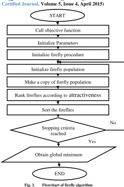
[image:3.612.325.577.117.496.2]The flowchart diagram of FFA is shown in Figure 3.
Fig. 3. Flowchart of firefly algorithm
IV. SIMULATION MODEL AND RESULT
The power system models in this paper were built using MATLAB. The figure 4 consists of two fully symmetrical areas linked together by two 230 kV lines of 220 km length. It was specifically designed in to study low frequency electromechanical oscillations in Two Area Four Machine (TAFM) power systems. Despite its small size, it mimics very closely the behavior of typical systems in actual operation. Each area is equipped with two identical round rotor generators rated 20 kV/ 900MVA. The synchronous machines have identical parameters, except for inertias which are H = 6.5s in area 1 and H = 6.175s in area 2.
START
Call objective function
Initialize Parameters
Sort the fireflies
Rank fireflies according to
attractiveness
Make a copy of firefly population Initialize firefly population
Initialize firefly procedure
Stopping criteria reached
Obtain global minimum
END
No
Yes
(4)
(6)
(6)
(2)
International Journal of Emerging Technology and Advanced Engineering
Website: www.ijetae.com (ISSN 2250-2459,ISO 9001:2008 Certified Journal, Volume 5, Issue 4, April 2015)
[image:4.612.335.549.123.262.2]564
Fig. 4. Performance of PSS in Two Area Four Machine (TAFM)
[image:4.612.56.272.127.245.2]In figure 4, area1 and area2 having the subsystem. Both the subsystem consists of two synchronous generators with identical parameters except the inertia constant. That was shown in figure 5 and figure 6.
Fig. 5. Area 1 consist of two synchronous machine with inertia constant 6.5s
Fig. 6. Area 2 consist of two synchronous machines with inertia constant 6.175s
In the figure 5 and figure 6, all the four synchronous generator‟s excitation system got the input signal from the PSS to enhance the system stability.
Fig. 7. PSS output signal given to the excitation system of synchronous machine
Above figure 7 consist of one generic Power System Stabilizers. The stabilized output of the PSS was given to the excitation system of the synchronous generator. In Two Area Four Machine (TAFM) system, each area consists of two PSS, totally four PSS. In figure 9.1 when the PSS constant block value „0‟ that represent there is no PSS. „1‟ means generic Power System Stabilizers activated.
A. Simulation results of TAFM system without PSS
Figure 8 and figure 9 shows the rotor angle deviation (dθ), rotor speed (ω), electrical power output (Pa), and
terminal voltage (Vt), positive sequence voltage of B1 and
[image:4.612.56.280.327.618.2]B2, active power form B1 and B2 of synchronous generators in Two Area Four Machine (TAFM) system without and with PSS.
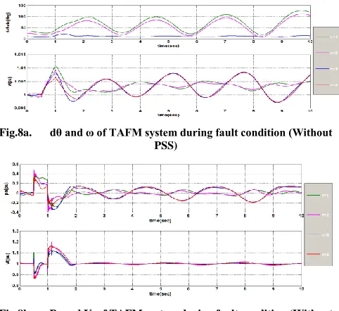
Fig.8a. dθ and ω of TAFM system during fault condition (Without PSS)
[image:4.612.326.567.446.667.2]International Journal of Emerging Technology and Advanced Engineering
Website: www.ijetae.com (ISSN 2250-2459,ISO 9001:2008 Certified Journal, Volume 5, Issue 4, April 2015)
[image:5.612.56.291.112.299.2]565
Fig.8c. Positive sequence voltage of B1 and B2, Active power form B1 and B2 of TAFM system during fault condition (without PSS)
Fig. 8. Two area four machine system during fault condition (Without PSS)
Figure 8 clearly shows the power system oscillation was not damped out without the installation of PSS in TAFM system during fault condition.
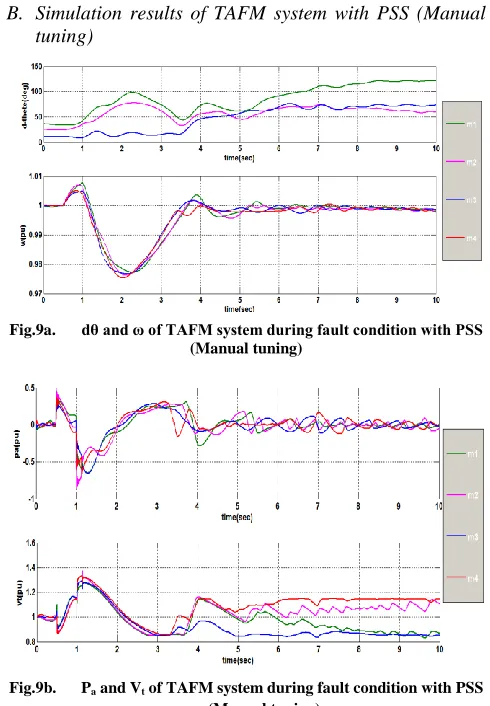
[image:5.612.328.554.143.300.2]B. Simulation results of TAFM system with PSS (Manual tuning)
Fig.9a. dθ and ω of TAFM system during fault condition with PSS (Manual tuning)
Fig.9b. Pa and Vt of TAFM system during fault condition with PSS (Manual tuning)
Fig.9c. Positive sequence voltage of B1 and B2, Active power form B1 and B2 of TAFM system during fault condition with PSS (Manual
tuning)
Fig. 9. Two area four machine system during fault condition (With PSS)
Figure 9 clearly shows the power system oscillation was damped out after the installation of PSS in TAFM system during fault condition. So the system is maintaining its stability during the disturbance condition.
C. Simulation results of TAFM system with PSS (with PSO)
TABLE 1
PARAMETERS USED FOR PSOALGORITHM
Table I shows the specified parameters for the PSO algorithm. Although the chances of PSO giving a local optimal solution are very few, sometimes getting a suboptimal solution is also possible. For different problems, it is possible that the same parameters for PSO do not give the best solution, and so these can be changed according to the situation.
TABLE 2
OPTIMIZED PSS PARAMETER USING PSO
Table II shows the optimal values of PSS parameters obtained by the PSO algorithm. Elapsed time is 394.429195 seconds.
PSO Parameters Value
Population Size 5
Maximum Iteration 20
Inertia Weight 0.8-0.9
PSS NO Tsensor Gain Washout
1 0.0163 39.2978 13.0028
2 0.0196 33.5747 6.7119
3 0.0110 20.6889 6.8687
[image:5.612.45.290.345.698.2] [image:5.612.350.570.618.682.2]International Journal of Emerging Technology and Advanced Engineering
Website: www.ijetae.com (ISSN 2250-2459,ISO 9001:2008 Certified Journal, Volume 5, Issue 4, April 2015)
566
Fig.10a. dθ and ω of TAFM system during fault condition with PSS (With PSO)
Fig.10b. Pa and Vt of TAFM system during fault condition with PSS (With PSO)
Fig.10c. Positive sequence voltage of B1 and B2, Active power form B1 and B2 of TAFM system during fault condition with PSS (With
PSO)
Fig. 10. Two area four machine system during fault condition With PSS (With PSO)
Figure 10 clearly shows the power system oscillation was damped out fastly compared to the TAFM system with manual tuning of Power System Stabilizer (PSS).
D. Simulation results of TAFM system with PSS (with FFA)
TABLE 3
PARAMETERS USED FOR FFA ALGORITHM
Table III shows the specified parameters for the FFA algorithm. And it also achieves better global optimal solution.
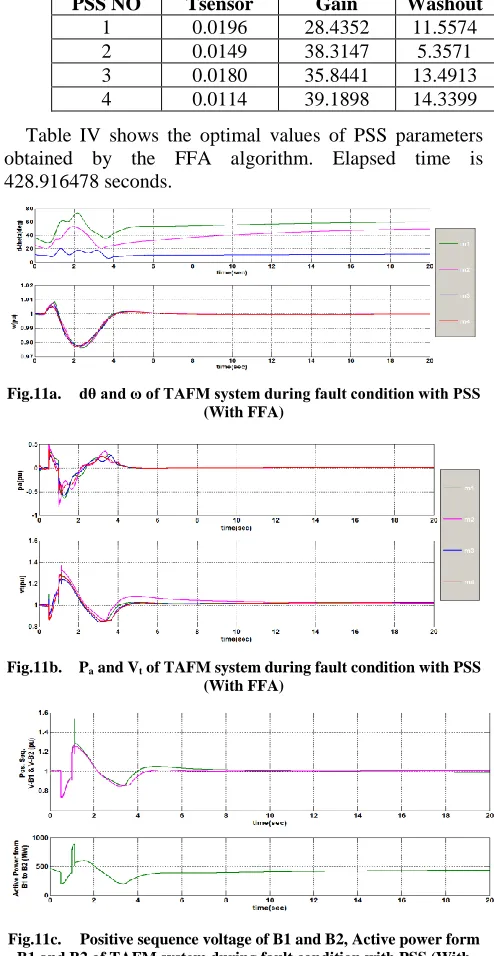
TABLE 4
OPTIMIZED PSS PARAMETER USING FFA
Table IV shows the optimal values of PSS parameters obtained by the FFA algorithm. Elapsed time is 428.916478 seconds.
Fig.11a. dθ and ω of TAFM system during fault condition with PSS (With FFA)
Fig.11b. Pa and Vt of TAFM system during fault condition with PSS (With FFA)
Fig.11c. Positive sequence voltage of B1 and B2, Active power form B1 and B2 of TAFM system during fault condition with PSS (With
[image:6.612.322.569.207.685.2]FFA)
Fig. 11. Two area four machine system during fault condition With PSS (With FFA)
FFA Parameters Value
Population Size 5
Maximum Iteration 20
Alpha 0.5
Beta 0.2
Gamma 1
PSS NO Tsensor Gain Washout
1 0.0196 28.4352 11.5574
2 0.0149 38.3147 5.3571
3 0.0180 35.8441 13.4913
[image:6.612.70.253.644.719.2]International Journal of Emerging Technology and Advanced Engineering
Website: www.ijetae.com (ISSN 2250-2459,ISO 9001:2008 Certified Journal, Volume 5, Issue 4, April 2015)
567
Figure 11 clearly shows the power system oscillation was damped out fastly compared to the TAFM system with (PSO)V. CONCLUSION
In this paper, a novel approach based on firefly optimization algorithm has been proposed for tuning the PSS parameters. Designing the optimal PSSs was converted to a multi-objective optimization problem and the FFA technique was employed to find the near optimum parameters of Power System Stabilizer to enhance the system stability. Main objectives in this project were minimizing rotor speed deviations and rotor angle in order to reduce the power system oscillation and enhance the system stability. The effectiveness of the proposed PSSs has been investigated on the Two Area Four Machine (TAFM) system under fault condition. Result obtained from the firefly algorithm (FFA) was compared to Particle Swarm Optimization (PSO). This comparison waveform clearly shown the TAFM system with firefly algorithm was better than the TAFM system with Particle Swarm Optimization. This work was done by using MATLAB.
REFERENCES
[1] P. Kundur, Power System Stability and Control. New York, NY, USA: McGraw Hill, 1994.
[2] B. Chaudhuri, B. C. Pal, A. C. Zolotas, I. M. Jaimoukha, and T. C. Green, “Mixed-sensitivity approach to H∞ control of power system oscillations employing multiple FACTS devices,” IEEE Trans. Power Syst., vol. 18, no. 3, pp. 1149–1156, Aug. 2003.
[3] Y.L. Abdel-Magid, M.A. Abido, Optimal multi-objective design of robust power system stabilizers using genetic algorithms, IEEE Transactions on Power Systems 18 (2003) 1125–1132.
[4] F. M. Hughes, O. Anaya-Lara, N. Jenkins, and G. Strbac, “A power system stabilizer for DFIG-based wind generation,” IEEE Trans. Power Syst., vol. 21, no. 8, pp. 763–772, May 2006.
[5] Siddhartha Panda, N. P. Padhy, “Robust power system stabilizer design using particle swarm optimization technique” International Journal of Electrical, Computer, Electronics and Communication Engineering Vol:2, No:10, 2008.
[6] H. Shayeghi, H.A. Shayanfar, A. Safari, R. Aghmasheh, “A robust PSS design using PSO in a multi-machine environment” Energy Conversion and Management (2009).
[7] H. Yassamia, A. Darabia, S.M.R. Rafieib, “Power system stabilizer design using Strength Pareto multi-objective optimization approach” Electric Power Systems Research 80 (2010) 838–846.
[8] T. Hussein, M.S. Saad, A.L. Elshafei, A. Bahgat, “Damping inter-area modes of oscillation using an adaptive fuzzy power system stabilizer” Electric Power Systems Research 80 (2010) 1428–1436. [9] N. Kshatriya, U. D. Annakkage, F.M. Hughes, and A. M. Gole,
“Optimized partial eigenstructure assignment - based design of a combined PSS and active damping 25, no. 2, pp. 866– 876, May 2010.
[10] Amir Hossein Gandomi, Xin-she yang, Amir Hossein Alavi, “Mixed variable structural optimization using firefly algorithm” Computers and Structures 89 (2011) 2325–2336.
[11] L. Fan, H. Yin, and Z. Miao, “On active/reactive power modulation of DFIG-based wind generation for interarea oscillation damping,” IEEE Trans. Energy Convers., vol. 26, no. 2, pp. 513–521, Jun. 2011.
[12] Jawad Talaq, “Optimal power system stabilizers for multi machine systems” Electrical Power and Energy Systems 43 (2012) 793–803. [13] Hossam e. Mostafa, Metwally a. el-Sharkawy, Adel a. Emary,
Kamel Yassin, “Design and allocation of power system stabilizers using the particle swarm optimization technique for an interconnected power system” Electrical Power and Energy Systems 34 (2012) 57–65.
[14] A. Ameli, M. Farrokhifard, A. Ahmadifar, A. Safari, H. A. Shayanfar, “Optimal Tuning of Power System Stabilizers in a Multi-Machine System Using Firefly Algorithm,” IEEE Transactions on power systems, 2012.
[15] Xin-She Yang and Amir H. Gandomi, Bat Algorithm: A Novel Approach for Global Engineering Optimization, Engineering Computations, Vol. 29, Issue 5, pp. 464--483 (2012).