Design of Electronic Throttle Valve Position Control
System using Nonlinear PID Controller
Shibly Ahmed AL-Samarraie
University of Technology Control and Systems Eng. Dept.
Iraq-Baghdad
Yasir Khudhair Abbas
University of Technology Control and Systems Eng. Dept.
Iraq-Baghdad
ABSTRACT
In recent years, the use of electronic throttle valve systems has been very popular in the automotive industry. It is used to regulate the amount of air flow into the engine. Due to the existence of multiple nonsmooth nonlinearities, the controller design to the electronic throttle valve becomes difficult task. These nonlinearities including stick–slip friction, backlash, and a discontinuous nonlinear spring involved in the system.
In the first part of this paper the electronic throttle valve system is presented first, and then the model is derived for each components of the throttle valve system. Later, the system dimension is reduced to two by ignoring the motor inductance at the end of this part of work. Actually this step enables us to design a nonlinear PID controller electronic throttle valve system.
The simulation results, of applying a nonlinear PID controller to the electronic throttle valve system, show the effectiveness of the proposed controller in forcing the angle of the throttle valve to the desired opening angle in presence of nonlinearities and disturbances in throttle valve system model.
General Terms
Nonlinear Control Systems, Throttle Valve System, Friction Model, Nonlinear Spring.
Keywords
Nonlinear PID Controller, Throttle valve system.
1.
INTRODUCTION
In trying to keep up with emissions and fuel efficiency laws, the fuel system used in modern cars has changed a lot over the years. One of the major components in an automobile engine is the throttle valve part. Designing a control system to the throttle valve is the newly common requirement trend in automotive technology. Controlling the throttling angle is the control of the plate opening angle which it controls the air amount that enters to the combustion engine. The air flow rate will directly control the output torque engine and consequently the speed will raised or lowered according to the demand. This reveals the importance of controlling the air fuel ratio. The air mass rate, traditionally, controlled according to the driver demand where the throttling angle is connecting directly to the accelerator by a wire. In this way, many internal and external conditions are ignored in determining the throttle angle such as fuel efficiency, road, or weather conditions which will negatively affects the engine overall efficiency [1]. To overcome the above deficiency an electronic control module (ECM) is used to accurately determining the required opining angle. Fig.1 shows the
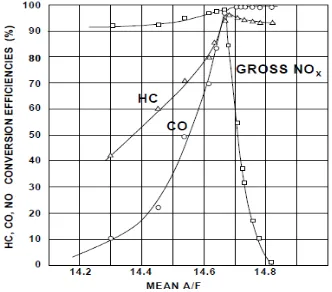
[image:1.595.315.559.399.550.2]details of the electronic control system. Accordingly, the electronic control unit (ECU) determines the precise amount of fuel delivered to the engine. This amount of fuel is just enough to achieve an ideal air fuel ratio (stoichiometry, about 14.7:1). The significance of controlling the air fuel ratio is well clarified in Fig. 2 where the emissions lowered to a minimum amount (conversion efficiencies of can be reached). The emission gases are like hydrocarbons ( ), carbon monoxide ( ) and nitrogen oxides ( ). For a deviations of air fuel ratio the conversion efficiencies of at least one of the emission components is drastically decreased as can be seen in Fig. 2 [2]. The electronic throttling valve, as shown in Fig. (3), consists of a dc motor, a motor pinion gear, an intermediate gear, a sector gear, a valve plate, and a nonlinear spring [1].
Figure 1. ECU (electronic control unit).
[image:1.595.344.510.589.735.2]Figure 3. The configuration of electronic throttling valve [1].
The problem of controlling the throttle valve plate position is frequently reviewed and searched in literature due to its importance in industrial applications. In 2008, Pan et al. [1] consolidate a variable structure concept with the employment of feedback backstepping techniques in the intermediate stages of design. In addition, the sliding mode observer design technique with equivalent control is exploited in order to estimate the values of necessary states that are not measured. The performance of the proposed controller is evaluated by performing some experiments on the throttle valve setup. For all the cases, the controller works rather well and meets the performance specifications.
The theory of sliding mode servo control is being utilized by Yokohama et al. in 1998 [3] for controlling the electronic throttle control (ETC) with highly nonlinear property due to two springs mounted for fail-safe. They designed a three sliding mode servo controllers in context of matching condition with the necessary experimental investigation. A higher order sliding mode control theory was used by Reichhartinger et al. in 2009 [4] to design a sliding mode controller to the throttling system. The higher order sliding mode concept eliminate the chattering arising in the classical sliding mode control theory and applied for system which have relative degree greater than one with respect to the switching function as in the case of the throttling system model.
A mathematical model for the electric throttle control system is presented by Chen et al. in 2010 [5], which include the preload spring with a piecewise linear spring constant. Different from the infinitely large spring constant assumption in previous researches, the elastic behavior of the ETC around the limp home position could be modeled by a linear spring. A two degree of freedom controller is designed and implemented based on the ETC model outside the limp-home position region with a low spring constant. It is shown that a control design based on the soft-spring ETC model is robust since the sensitivity function decreases as the spring constant increases. The pole-placement designed ETC controller consists of feedforward and feedback functions. The integral control function with anti-windup feature in the feedback control loop can compensate the friction force completely. And the feedforward control compensates the phase lag resulted from the feedback loop.
An adaptive inverse model control system (AIMCS) is designed by Yuan Xiaofang et al. in 2010 [6] for the electronic throttle, with utilizing the two radial basis function (RBF) neural networks in the AIMCS. Two RBF networks
were used; the first is to identify the plant by a RBF networks identifier. This provides the sensitivity information of the plant to the control input, while the second RBF networks is exploited as inverse model controller established by inverse system method. The RBF networks are learned offline firstly and are trained online using back propagation algorithms. Then the adaptive learning rates are developed to guarantee convergence and for faster learning.
Mario Vašak et al. in 2007 [7] perform the controller synthesis for the piecewise affine (PWA) model of the throttle system in discrete time by solving a constrained time-optimal control problem and propose a procedure to model friction in a discrete-time PWA form that is suitable both for simulation and controller design purposes. Although the control action computation, in general, can be restated as a mixed-integer program but due to the small sampling time, solving such a program online (in a receding horizon fashion) would be very prohibitive which resolved by applying recent theoretical results that enable offline pre-computation of the state-feedback optimal control law in the form of a lookup table. The designed time-optimal controller achieves considerably faster transient, while preserving other important performance measures, like the absence of overshoot and static accuracy within the measurement resolution.
The technique employs invariant set computation and reachability analysis. The experimental results on a real electronic throttle are reported and compared with a tuned PID controller that comprises a feedforward compensation of the process nonlinearities.
The designed time-optimal controller achieves considerably faster transient, while preserving other important performance measures, like the absence of overshoot and static accuracy within the measurement resolution.
The mathematical model of a throttle valve considered here is nonlinear which it contains discontinuous terms due to Coulomb friction and a nonlinear spring uses the signum function in its model as will be derived later. Due to this complexity, a nonlinear PID controller is suggested in the present work to attenuate the effect of discontinues terms and regulates the throttle angle to a value near the desired one. The proposed nonlinear PID controller consists of a linear proportional term, a linear derivative term and a nonlinear integral term. All of these terms use the error function between the throttle angle and the desired one.
2.
MODEL DESCRIPTION OF THE
ELECTRONIC THROTTLE VALVE
SYSTEM
The mathematical model of the electronic throttle valve is derived based on the work given in [1] and Table (1) consists of the parameter names and their definitions used in the derivation of the throttle valve’s mathematical model. After that and by considering the motor inductance as a small value the model dimension is reduced by one.
2.1
Friction
[image:3.595.60.275.158.297.2]Friction is a nonlinear phenomenon in which a force that produced is tends to oppose the motion of throttle plate such as coulomb, static, viscous, stribeck, etc. In this work the coulomb friction is considered. Static friction phenomena only have a static dependency on velocity. The Coulomb friction model is demonstrated in the Fig. (4) below.
Figure 4. Coulomb friction.
Consequently the Coulomb friction model mathematically is given by
(1)
where
: is a positive constant.
2.2
Nonlinear Spring:
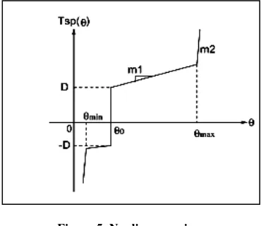
The typical feature of the electronic throttle valve includes a stiff spring, which is used as a fail-safe mechanism. This spring forces the valve plate to return to the position slightly above the closed position when no power is applied so that the small amount of air can be supplied into the engine when no control is available in order to prevent a sudden lock of engine revolution while the vehicle is in motion. Moreover, the motion of the valve plate is limit between the maximum and minimum angles. These limited stops are realized by a highly stiff spring, ideally with infinite gain. The characteristic of the modeled spring is shown in Fig. (5).
Figure 5. Nonlinear spring.
The nonlinear relation plotted in Fig. 5 may be written by the following form
Or
(2)
Due to the clearance formed between a pair of mounted gears, the gear backlash is another nonlinearity source in addition to friction and the nonlinear spring. In this work the nonlinearity coming from backlash phenomenon is ignored when writing the throttle valve mathematical model.
3.
THE FULL MODEL OF THE
ELECTRONIC THROTTLE VALVE
Therotor angular velocity is defined as , and the valve plate position is defined as . The total inertia and total damping coefficient are respectively determined by:
(3) (4)
Considering the friction and nonlinear spring torque, the dynamic equation is obtained:
(5) Where : is the current through the dc motor windings. The relationship between the valve plate position and the rotor angular velocity is described by the following relation:
(6)
As a result, including motor electrical part, the model of throttle system:
(7)
where : is the input voltage to the dc motor and the nonlinear functions and are as described in Eq. (1) and (2)
respectively. Now, let and , the state space form of equations (7) accordingly is written as:
(8)
4.
THE REDUCED MODEL OF THE
ELECTRONIC THROTTLE VALVE
To simplify the model, the motor inductance is ignored and accordingly the throttle valve dynamical system in Eq. (8) reduced to a system with lower dimension as in the following steps:
[image:3.595.74.259.567.727.2]
, Solving for we get:
(9)
Now by substitute the value of from Eq. (9) in Eq. (8), we get:
(10)
The nominal parameters values considered in the system model are given in the Table (2). The throttle valve system model given in Eq. (10) is a second order system and will be used in designing a nonlinear PID controller that force the state to track a certain desired throttle angle (system output).
5.
NON-LINEAR PID CONTROLLER
DESIGN
In this section, we propose a nonlinear structure for the well known PID controller. Replacing the integral for the error function by an integral for the arc tan function to the error in the PID controller, yields a nonlinear PID controller and it will be used later in the throttle valve system. When disturbance which acting on the system dynamics is constant, the linear PID controller is adequate where the control action force the state to follow the desired reference [8]. When the disturbance term is not constant, the linear PID will be able only to attenuate the disturbance effect with a linear integral control term. For a bounded disturbance the state will be regulated to a region around the equilibrium point and the size of this region is directly depends on the disturbance bound and the PID control parameters. In all cases (wither in linear or nonlinear PID structures) the disturbance attenuation ability depends mainly on the integral term, since its effects is integrated and increased with time to rejects the disturbance. Unfortunately the integral term cannot remove the disturbance effects, rather than that it enters the system response in a limit cycle. The size of the limit cycle can be reduced via increasing the integral gain especially when starting near the equilibrium point. In the other case, when the state starts away from the equilibrium point, the control may saturate and the control system is winding up. The idea which proposed in this work is to use an integral control for the error function with large gain when the state is near the equilibrium point and outside a certain bound to the equilibrium point an integral control but for a constant value. In this case we preserve the integral control activity when the state starts away from the equilibrium point and the linear integral control ability in maintaining the state closely near the equilibrium point. The saturation function can be used in the integral term with the desired gain near the equilibrium point where the ultimate bound for the limit cycle can be easily specified. Namely the nonlinear PID control in this case is:
(11-a)
where is an odd function given by
(11-b)
and is a design parameter which can be adjusted to specify the limit cycle size. In the present work we will use the arc tan function which it is a differentiable odd function instead of the saturation function. Accordingly the proposed nonlinear PID control is:
(11-c)
where is a design parameter has the same function as when the control uses the saturation function. The control law in Eq. (11-c) may be written in a more useful form:
(12)
5.1
NONLINEAR
PID
CONTROL
DESIGN
FOR
ELECTRONIC
THROTTLE VALVE
In this section a non-linear PID controller that deals with the nonlinear difficulties is proposed. To use a linear PID control for a nonlinear systems, the controller gains , , and are tuned. Most of the tuning rules are based on obtaining linear model of the system, either through running step tests or by linearzing a nonlinear model around the operating steady-state, and then computing parameters values of the controller that accomplished the stability, performance and robustness objectives in the closed loop System .While the use of linear models for the PID controller tuning makes the tuning process easy, the underlying dynamics of many processes are often highly complex, due to inherent nonlinearity of the process and then the controller may be unable to stabilize the closed loop system and may call for extensive re-tuning of the controller parameters. The shortcomings of classical controllers in dealing with complex process dynamics, together with the abundance of such complexities in modern day processes, have motivated a significant and growing body of research work within the area of nonlinear process control over the past two decades, leading to the development of several practically. The nonlinear control strategies can deal effectively with a wide range of process control problems such as nonlinearities, constraints, uncertainties, and time delays [9]. In this work a nonlinear PID controller is proposed for the electronic throttle valve system. The results showed the effectiveness of this type of controller in dealing with the inherent nonlinearity in system model and in forcing the state to the desired point.
In the proposed controller, the arc tan function is used in the integral part instead of the direct error. The advantage of using the arc tan function (atan in MATLAB language) is the ability for attenuating the effect of variable disturbances representing by discontinuous nonlinearity with uncertain
parameters. As in the case of linear PID controller,
proposed nonlinear PID controller is given by the following law:
(13)
Where the value of
and .
The simulations in the subsequent section are done first on the reduced model of the electronic throttle valve as described in Eq. (10), and then on the total model, without ignoring the inductance, as found in Eq. (8). The control efforts is saturated within the limits of ( ) due to the dc motor input voltage range.
6.
SIMULATION
RESULTS
AND
DISCUSSION
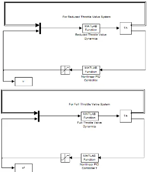
The simulation results are obtained using Matlab/Simulink (Ver. 14.9). The simulink model for the throttle valve system are shown in Fig. (8), while the nonlinear PID block subsystem is shown in Fig. (9). To validate the model reduction step which it is used in controller design, the simulations are achieved for both reduced and full order systems in the following subsections 6.1 and 6.2 respectively.
Figure (8): Matlab/Simulink Model for both reduced and full order throttle valve system with nonlinear PID
[image:5.595.317.544.139.255.2]Controller.
Figure 9. Nonlinear PID Simulink block.
6.1
Reduced Order Model Simulation
Results
The first simulation test is done using the proposed controller in Eq. (13), based on the reduced model. Fig. (10) shows the
simulation result for the angle with time where the control command is aimed to open the throttle angle by degree ( ). The initial condition for this test is: . The settling time is found to be about 0.03 second for error tolerance around the reference throttle angle.
Figure 10. Valve Plate Position Angle ( ) time history for reduced order throttle valve system with nonlinear PID
controller.
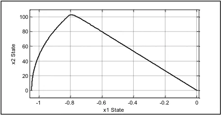
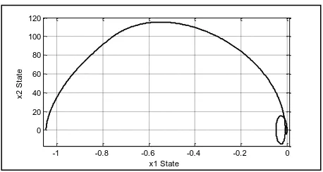
[image:5.595.93.243.340.514.2]The plot of the DC motor input voltage, as the control input simulation results is revealed in Fig. (11).It can be seen clearly that at the first 0.003 second of simulation, the controller efforts exceed the actuator limits ( ). In addition, the phase plot is shown in Fig. (12) which again proves the effectiveness of the proposed controller to track the system to the desired position.
[image:5.595.316.544.390.505.2]Figure 11. Control action ( ) time history for reduced order throttle valve system with nonlinear PID controller.
Figure 12. phase plot of vs. for the reduced order throttle valve system with nonlinear PID controller.
To show the ability of the proposed controller to deal with parameter perturbation, an uncertainty in the parameter values of the system model equal to (50%) is considered in the simulation tests. As shown in the figures below that the system still keeping his stability and specifications even if the
0 0.02 0.04 0.06 0.08 0.1
0 0.2 0.4 0.6 0.8 1 1.2
Time (sec)
T
h
e
ta
(
ra
d
)
Desired Plate Position Valve Plate Position
0 0.02 0.04 0.06 0.08 0.1
-2 0 2 4 6 8 10 12
Time (sec)
D
C
M
o
to
r
In
p
u
t
V
o
lt
a
g
e
(
v
)
-1 -0.8 -0.6 -0.4 -0.2 0
0 20 40 60 80 100 120
x1 State
x
2
S
ta
[image:5.595.315.544.546.667.2] [image:5.595.70.258.562.688.2]parameters is altered by (50%) which show the ability and potential of the proposed nonlinear PID controller.
Figure 13. Valve Plate Position Angle ( ) time history for reduced order system with nonlinear PID controller with
[image:6.595.54.283.104.221.2]parametric uncertainty (50%).
Figure 14. Control action ( ) time history for reduced order throttle valve system with nonlinear PID controller
[image:6.595.316.545.228.348.2]with parametric uncertainty (50%).
Figure 15. Phase plot of vs. for the reduced order throttle valve system with nonlinear PID controller with parametric
uncertainty (50%).
6.2
Full Order Model Simulation Results
Now we test the proposed controller in Eq. (13) on the original model without ignoring the inductance, as found in Eq. (7) to prove the ability of the nonlinear PID controller to work in the complete system model without simplification.
[image:6.595.52.284.273.392.2]Figure 16. Valve Plate Position Angle ( ) time history for original full order throttle valve system with nonlinear PID controller.
[image:6.595.315.544.384.505.2]Figure 17. Control action ( ) time history for original full order throttle valve system with nonlinear PID controller.
Figure 18. phase plot of vs. for the original full order throttle valve system with nonlinear PID controller.
Figure 19. Valve Plate Position Angle ( ) time history for original full order system with nonlinear PID controller
with parametric uncertainty (50%).
0 0.02 0.04 0.06 0.08 0.1
0 0.2 0.4 0.6 0.8 1 1.2 Time (sec) T h e ta ( ra d )
Desired Plate Position Valve Plate Position
0 0.02 0.04 0.06 0.08 0.1
-5 0 5 10 Time (sec) D C M o to r In p u t V o lt a g e ( v o lt s )
-1 -0.8 -0.6 -0.4 -0.2 0
0 20 40 60 80 100 x1 State x 2 S ta te
0 0.02 0.04 0.06 0.08 0.1
0 0.2 0.4 0.6 0.8 1 1.2 Time (sec) T h e ta ( ra d )
Desired Plate Position Valve Plate Position
0 0.02 0.04 0.06 0.08 0.1
-10 -5 0 5 10 Time (sec) D C M o to r In p u t V o lt a g e ( v o lt s )
-1 -0.8 -0.6 -0.4 -0.2 0
0 20 40 60 80 100 120 x1 State x 2 S ta te
0 0.02 0.04 0.06 0.08 0.1
0 0.2 0.4 0.6 0.8 1 1.2 Time (sec) T h e ta ( ra d )
[image:6.595.54.282.442.567.2] [image:6.595.315.545.544.663.2]Figure 20. Control action ( ) time history for original full order throttle valve system with nonlinear PID controller
with parametric uncertainty (50%).
Figure 21. Phase plot of vs. for the original full order throttle valve system with nonlinear PID controller with
parametric uncertainty (50%).
The simulation results (figures (4.9)-(4.14)) reveals the capability of the nonlinear PID controller to deal with the full throttle valve system model, and keeping the system with the same specifications achieved with the reduced model. It is obvious that the robustness potential of the controller is assured while it handles the system with the desired target with a 50% parametric uncertainty enforced to test the controller performance.
7.
CONCLUSIONS
In this work a nonlinear control law is proposed for controlling the angle of the throttle valve as one of the major components in an automobile engine. The proposed control law replaces the integral of the conventional PID controller by an integral term that uses the arc tan function for the error instead of the linear error function. This helps greatly in attenuating the effects of the discontinuous nonlinear terms act on the throttle system dynamics due to the friction and to the presents of the nonlinear spring. The effectiveness of the proposed control law to force the throttle angle to track the desired reference is proved via the numerical simulations based on the reduced and non-reduced system model. This
result showed the ability of the nonlinear PID controller to work in the complete system model without simplification. Also it showed that the control system is robust to the variations of system parameters up to 50% percent. Finally, it can be say that due to the simplicity of the control strategy that is offered in this paper, and the robustness properties of the designed control system with respect to variation of process parameters, which can be caused by production deviations and variations of external conditions, we can recommend this control strategy for effective and law cost microcontroller system implementation.
8.
REFERENCES
[1] Pan, Y., Özgüner, Ü., and Dagci. O. H., 2008. Variable-Structure Control of Electronic Throttle Valve, IEEE Transactions on Industrial Electronics, vol. 55, no. 11, 3899-3907.
[2] Jun-Mo Kang and Grizzle J. W., 1999 "Nonlinear Control for Joint Air and Fuel Management in a SI Engine", Proceedings of the 1999 American Control Conference. [3] Yokoyama, M., Shimizu', K., and Okamoto, N. 1998.
Application of Sliding-Mode Servo Controllers to Electronic Throttle Control, Proceedings of the 37th IEEE Conference on Decision & Control, 1541-1545.
[4] Reichhartinger M. and Horn M. 2009. Application of Higher Order Sliding-Mode Concepts to a Throttle Actuator for Gasoline Engines, IEEE Transaction on Industrial Electronics, Vol. 56, No. 9, 3322-3329.
[5] Chen, C-H., Tsai, H-L., and Lin, Y.-S. 2010. Servo Control Design for Electronic Throttle Valve with Nonlinear Spring Effect. The 11th IEEE International Workshop on Advanced Motion Control. 88-93.
[6] Yuan Xiaofang, Wang Yaonan, Sun Wei, and Wu Lianghong., 2010. RBF Networks-Based Adaptive Inverse Model Control Systemfor Electronic Throttle, IEEE Transactions on Control Systems Technology, Vol. 18, No. 3, May 2010.
[7] Mario Vašak, Mato Baoti´c, Ivan Petrovi´c, and Nedjeljko Peri´c, 2007. Hybrid Theory-Based Time-Optimal Control of an Electronic Throttle. IEEE Transactions on Industrial Electronics, Vol. 54, No. 3, June, 1483-1494.
[8] Khalil. H. K. 2002. Nonlinear Systems. 3rd edition, Prantice Hall, New Jersey.
[9] Mhaskar, P. N., El-Farra, N. H., and D. Christofides .2004. A Method for PID Controller Tuning Using Nonlinear Control Techniques. Proceeding of the 2004 American Control Conference, 2925-2930.
0 0.02 0.04 0.06 0.08 0.1
-10 -5 0 5 10
Time (sec)
D
C
M
o
to
r
In
p
u
t
V
o
lt
a
g
e
(
v
o
lt
s
)
-1 -0.8 -0.6 -0.4 -0.2 0
0 20 40 60 80 100 120
x1 State
x
2
S
ta
[image:7.595.54.283.239.361.2]International Journal of Computer Applications (0975 – 8887) Volume 59– No.15, December 2012
Table 1. The parameter names and their definitions used in the derivation of the throttle valve’s mathematical
model [1].
Definition Parameters
Inertia of rotor.
Inertia of intermediate gear.
Inertia of sector gear.
Inertia of plate and shaft.
Viscous damping constant of motor.
Viscous damping constant of intermediate gear.
Viscous damping constant of plate and shaft.
Tooth number of pinion gear.
Tooth number of large intermediate gear.
Tooth number of small intermediate gear.
Tooth number of sector gear.
Motor inductance.
Motor resistance.
Motor torque constant.
Motor back emf constant.
Reset integrator gain.
Spring default position.
Spring max position.
θ
Spring min position.
θ
Spring offset.
Spring gain.
Spring limit stop gain.
Table 2. Nominal parameter values for simplified model [1].
Parameters Values
![Figure 3. The configuration of electronic throttling valve [1].](https://thumb-us.123doks.com/thumbv2/123dok_us/8096161.786234/2.595.69.265.71.228/figure-configuration-electronic-throttling-valve.webp)
![Table 1. The parameter names and their definitions used in the derivation of the throttle valve’s mathematical model [1]](https://thumb-us.123doks.com/thumbv2/123dok_us/8096161.786234/8.595.348.547.88.311/table-parameter-names-definitions-derivation-throttle-valve-mathematical.webp)
