Neural based Post Processing Filtering Technique
for Image Quality Enhancement
R. Pushpavalli
Ph.D Scholar,
Department of Electronics and Communication Engineering,
Pondicherry Engineering College,
Puducherry-605 014, India.
G. Sivaradje
Associate Professor, Department of Electronics and
Communication Engineering, Pondicherry Engineering
College,
Puducherry-605 014, India.
E. Srinivasan and
S.Himavathi*
Professors
Department of Electronics and Communication Engineering, Department of Electronics and
Electrical Engineering* Pondicherry Engineering
College,
Puducherry-605 014, India.
ABSTRACT:
Digital images are often affected by impulse noise during image acquisition and/or transmission over communication channel. A Neural Based Post Processing Technique for Image Quality Enhancement (NBPPTIQE) for enhancing digital images corrupted by impulse noise is proposed in this paper. The proposed filter is an intelligent filter obtained by aptly combining a Nonlinear Filter (NF), Modified Canny Edge Detector (MCED) and a Feed forward Adaptive Neural (FAN) Network. The internal parameters of the Feed Forward Neural Network are adaptively optimized by training of well known images. The most distinctive feature of the proposed filter offers good line, edge, and fine detail preservation performance and also effectively removes impulse noise from the image. Extensive simulation results show that the proposed Post Processing Technique can be used for efficient enhancement of digital images corrupted by impulse noise without distorting useful information in the image. The performance of proposed filter is compared with median based filter and Neural Filter and shown to be more effective in terms of eliminating impulse noise and preserving edges and fine details of digital images.
Key Words
Feed forward Adaptive Neural Network, Impulse Noise, Nonlinear Filter, Order Statistics Filters and Post Processing Technique.
1.
INTRODUCTION
The acquisition or transmission of digital images through sensors or communication channels is often accompanied by contamination with impulse noise. It is imperative, and even indispensable, to remove these corrupted pixels to facilitate subsequent image processing operations. Existing switching-based median filters [1-13] are commonly found to be non-adaptive to noise density variations and prone to misclassifying pixel characteristics at high noise density interference. This reveals the critical need to evolve a sophisticated switching scheme and median filter.
In order to address these issues, it is proposed to study and investigate new switching-based median filtering schemes called Rank Order Filtering (ROF) techniques [14-17]. The primary objective of these contemplated schemes is to achieve improved filtering performance in terms of removing impulse noise while preserving edge structures and signal details.
These ROF schemes are proposed to be designed to avoid any damage to good pixels while performing filtering operation. The decision based filtering [18-22] procedure consists of the following two steps: (i) an impulse detector that classifies the input pixels as either corrupted pixels or uncorrupted pixels, (ii) a noise removal filter that aims to restore those pixels that are classified as corrupted pixels. These proposed techniques aim to achieve optimal performance over the entire image. A good noise filter is required to satisfy two criteria, namely, suppressing the noise and preserving the useful information in the signal. Unfortunately, a great majority of currently available noise filters cannot simultaneously satisfy both of these criteria. This work aims at achieving good de-noising without compromising on the useful information of the signal.
In order to achieve superior denoising performance, a Nonlinear Filtering Technique (NFT) has been proposed for removing impulse noise from the images. The proposed NFT detects whether a pixel is noisy or noise-free. If the pixel is noise-free, the filtering window is moved forward to process the next pixel. On the other hand, if the pixel is a noisy one, then it is replaced by the median pixel value if it is not an impulse; otherwise, the pixel is replaced by the already processed immediate top neighbouring pixel in the filtering window. The proposed NFT is shown to exhibit good response at signal edges besides effectively filtering the noise.
In order to achieve the objectives of denoising and preserving the essential signal characteristics, a neural based post processing has been introduced in the NFT. In 1986, Canny proposed the edge detection operator based on optimization algorithm. Image edge is a fundamental feature of image, which contains abundant internal information such as direction, step characteristics, shape and etc [23].
Hybrid filters have been investigated [24 and 25]. These filters eliminate impulse noise satisfactorily. Even though, intelligent techniques required certain pattern of data’s to learn the input. This pattern is given through conventional filter for training of the input. Therefore, hybrid filter performance depends on conventional filters performance.
can be viewed as a powerful nonlinear mapping. Conceptually, a feed forward adaptive network is actually a static mapping between its input and output spaces; this mapping may be either a simple linear relationship or a highly nonlinear one, depending on the network structure (node arrangement and connections, and so on) and the functionality of the system.
In order to achieve image enhancement when digital image are corrupted by higher level of impulse noise, a new neural based technique is proposed and is referred as Neural Based Post Processing Filtering Technique (NBPPFT) for image enhancement. In this paper, existing canny edge detector output is slightly modified and used to improve the learning processes of neural network.
Feed forward network is considered for Post Processing Technique, which is implemented in the framework of adaptive network. The neural network learning procedure is used for the proposed filter and neural network can construct an input-output mapping which is based on both learning and understanding. Neural network is trained using well known images and network structure is fixed. Noisy image (input image), Nonlinear Filtering Technique (NFT), Modified Canny Edge Detector (MCED) output image are considered as three inputs for neural network and noise free image is considered as a target image for Training of the neural network. While training a neural network, network structure is fixed and the unknown images are tested for given fixed network structure respectively. To ensure faster processing, only the corrupted pixels from test images are identified and processed by the optimized neural network structure. As the uncorrupted pixels do not require further processing, they are directly taken as the output. The performance evaluation is obtained through simulation results and shown to be superior performance to other existing filtering techniques in terms of impulse noise elimination and edges and fine detail preservation properties.
The rest of the paper is organized as follows. Section 2 explains the structure of the proposed filter and its building blocks. Section 3 discusses the result of the proposed NBPPTIE to the test images. Results of the experiments conducted to evaluate the performance of the proposed hybrid filter and comparative discussion of these results are also presented in this Section 3. 4 is the final section, presents the conclusions.
2.
PROPOSED FILTER
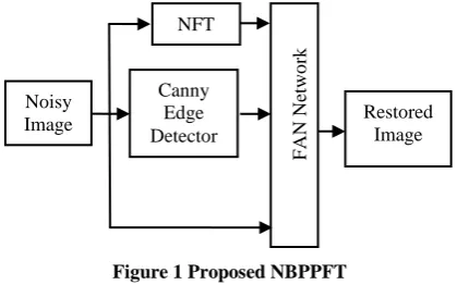
[image:2.595.323.533.75.206.2]A Feed forward Adaptive Neural Network is a flexible system trained by heuristic learning techniques derived from neural networks can be viewed as a 3-layer neural network with weights and activation functions. Figure 1 shows the structure of the proposed impulse noise removal filter. The proposed filter is a filter obtained by appropriately combining a noisy image, output image from Nonlinear Filtering Technique and Modified Canny Edge Detector output and neural network. The neural network utilizes the information from the NFT, the modified canny edge detector and the noisy input image to compute the output of the system, which is equal to the restored value of the noisy input pixel.
Figure 1 Proposed NBPPFT
2.1 Nonlinear Filtering Technique (NFT)
The impulse noise detection is based on the assumption that a corrupted pixel takes a gray value which is significantly different from its neighboring pixels in the filtering window; whereas noise-free regions in the image have locally smoothly varying gray levels separated by edges. In widely used Standard Median Filter (SMF) and Adaptive Median Filter (AMF), only median values are used for the replacement of the corrupted pixels. In switching median filter, the difference between the median value of pixels in the filtering window and the current pixel value is compared with a threshold to determine the presence of impulse. If the current pixel is detected to have been corrupted by impulse noise then the pixel is subjected to filtering; otherwise, the pixel is left undisturbed. The filtering technique proposed in this paper detects the impulse noise in the image using a decision mechanism. The corrupted and uncorrupted pixels in the image are detected by comparing the pixel value with the maximum and minimum values in the selected window. If the pixel intensity lies between these minimum and maximum values, then it is an uncorrupted pixel and left undisturbed. If the value does not lie within the range, then it is a corrupted pixel and is replaced by the median pixel value or already processed immediate neighboring pixel in the current filtering window.
Consider an image of size N×N having 8-bit gray scale pixel resolution. The steps involved in detecting the presence of an impulse or not are described as follows:
Step 1) A two dimensional square filtering window of size 3 x 3 is slid over a highly contaminated image.
Step2) The pixels inside the window are sorted out in ascending order.
Step3) Minimum, maximum and median of the pixel values in the processing window is determined. In this case, the minimum, maximum and median pixel values, respectively, are 0, 255 and 255.
Step 4) If the central pixel lies between minimum and maximum values, then it is detected as an uncorrupted pixel and the pixel is left undisturbed. Otherwise, it is considered a corrupted pixel value. In the present case, the central pixel value 255 does not lie between minimum and maximum values. Therefore, the pixel is detected to be a corrupted pixel.
167 168 169 170 170 167 255 255 0 255 164 255 255 255 255 165 0 255 255 255 166 255 159 255 255
0 168 169 170 255 255 255 255 255 Noisy
Image
NFT
Canny Edge Detector
F
AN
Ne
two
rk
Step 5) The corrupted central pixel is replaced by the median of the filtering window, if the median value is not an impulse. If the median value itself is an impulse then the central pixel is replaced by the already processed immediate top neighboring pixel Xi-1,j in the filtering window.
In the present case, the median value is also an impulse and therefore, the pixel is replaced by its already processed top neighboring pixel value 69.
Then the window is moved to form a new set of values, with the next pixel to be processed at the centre of the window. This process is repeated until the last image pixel is processed. This Impulse noise detection and filtering is based on the following condition:
if Xmin < Xi,j < Xmax {Xi,j is a noiseless pixel;
no filtering is performed on Xi,j } else
{Xi,j is a noisy pixel; determine the median value} if median ≠0 and median ≠ 255 {Median filter is performed on Xi,j} Xi,j = Xmed
else
{Median itself is noisy} Xi,j = Xi-1,j
end;
end;
where, Xi,j is the intensity of central pixel inside the filtering window, Xmin, Xmax and Xmed are the minimum, maximum and median pixel value in filtering window of noisy image. Xi-1,j is the intensity of the already processed immediate top neighboring pixel. In order to process the border pixels, the first and last columns, respectively are replicated at the front and rear ends of the image matrix; similarly, the first and last rows, respectively, are replicated at top and bottom of the image. The first row pixels of the image are processed using the same algorithm described above except that in step 5, if the median value is also detected to be an impulse it is replaced by one of the uncorrupted nearest neighborhood pixel values in the processing window.
2.2. Edge Detector
Edge detection is a fundamental tool in image processing and computer vision, particularly in the areas of feature detection and feature extraction, which aim at identifying points in a digital image at which the image brightness changes sharply or more formally has discontinuities. In this paper, canny edge detector is utilized in different aspect to identify the edges of the image and also improve the learning process of neural network.
The canny edge detector is considered for training and testing of the images in this proposed Filtering Technique. Usually, edge detector output of the pixels on image is described by means of binary values respectively are 1 and 0. Edges of the image are represented using binary value 1 and homogeneous regions of the image are represented using binary value 0 respectively. The inputs for Feed forward Adaptive Neural Network are noisy image, NFT output image and Modified Canny Edge Detector (MCED) output image. Normalized
values of these three inputs are given to the neural network. This neural network structure already explained in Fig.1. After normalizing the input data’s, the noisy image data’s and modified edge detector output data’s are approximately similar data density values. Because normalized noisy image data’s contain binary values of 1 and 0 for salt and pepper noise respectively, Those 1 and 0 are depending on the percentage of noise contaminate the received image from communication channel. Canny edge detected output data’s are also contain binary values of 1 for edges and binary value of 0 for homogenous region of image respectively. Therefore neural network entails difficulties to learn logically identify the error data’s from the given input image. In order to improve the learning performance of neural network, canny edge detector output is utilized in different way.
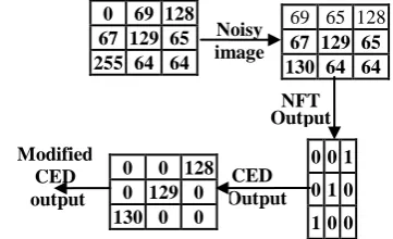
[image:3.595.353.504.294.399.2]Canny Edge Detector is performed on noise free image as a target image and its edges are replaced by original intensity values of its corresponding noise free image for training. Example; a two dimensional square window of size 3 x 3 and the pixels inside the window are considered as an example for new edge detector output and is shown below:
Figure 2 Modified Canny Edge Detector for training
This Modified CED output gives superior performance for learning of neural network in terms of edge and fine detail preservation of images.
[image:3.595.338.519.544.654.2]
In order to test the images, NFT is applied on noisy image and this filtered image is considered as input for canny edge detector and then edges from canny edge detector are replaced by original intensity values of its corresponding NFT image data. A two dimensional square window of size 3 x 3 and the pixels inside the window are considered as an example for a new edge detector output and is shown below:
Figure 3 Modified Canny Edge Detector for testing
2.3. Feed forward Adaptive Neural
Network
In FAN network, Back propagation algorithm is computationally effective and works well with optimization and adaptive techniques, which makes it very attractive in dynamic nonlinear systems. This network is popular general nonlinear modeling tools because it is very suitable for tuning 167 168 169 170 170
167 255 169 0 255 164 255 255 255 255 165 0 255 255 255 166 255 159 255 255
Modified CED output
CED Output
0 0 128 0 129 0 130 0 0 Noise
Free image 69 65 128 67 129 65 130 64 64
0 0 1
0 1 0
1 0 0
Modified CED output
NFT Output
CED Output 0 0 128 0 129 0 130 0 0
Noisy image
69 65 128
67 129 65 130 64 64
0 0 1 0 1 0
1 0 0 0 69 128
by optimization and one to one mapping between input and output data’s. This architecture shows the input-output relationship of the network is as follows in Figure.4.
Figure 4 xm represents the total number of input pixels as
data’s and Nn represents the number of neurons in the hidden
unit. A feed forward back propagation neural network consists of two layers. The first layer, or hidden layer, has a tan sigmoid (tan-sig) activation function, and the second layer, or output layer, has a linear activation function. Thus, the first layer limits the output to a narrow range, from which the linear layer can produce all values.
Figure 4 Feed forward Adaptive Neural Network Architecture
The output of each layer can be represented by
Y
Nx
1
f W
(
NxM
X
M
,1
b
N
,1
)
(1) where Yis a vector containing the output from each of the N neurons in a given layer, Wis a matrix containing the weights for each of the M inputs for all N neurons, X is a vector containing the inputs, bis a vector containing the biases and f(·) is the activation function.
The trained network was created using the neural network toolbox from Matlab9b.0 release. In a Backpropagation network, there are two steps during training that are used alternately. The Backpropagation step calculates the error in the gradient descent and propagates it backwards to each neuron in the output layer, then hidden layer. In the second step, depends upon the values of activation function from hidden layer, the weights and biases are then recomputed, and the output from the activated neurons is then propagated forward from the hidden layer to the output layer. The network is initialized with random weights and biases, and was then trained using the Levenberq-Marquardt algorithm (LM). The weights and biases are updated according to
Dn
1
Dn
[
JTJ
mI
}
1
JTe
(2) where Dn is a matrix containing the current weights and biases, Dn+1 is a matrix containing the new weights and biases, e is the network error, J is a Jacobean matrix containing the 1st derivative of e with respect to the currentweights and biases, I is the identity matrix and m is a variable that increases or decreases based on the performance function. The gradient of the error surface, g, is equal to JTe.
2.4. Training of the Feed forward Adaptive
Neural Network
[image:4.595.78.258.203.439.2]The FAN network is used in the structure of the proposed filter acts like a mixture operator and attempts to construct an enhanced output image by combining the information from the NFT, the Modified Canny Edge Detector and the noisy input image. The rules of mixture are represented by the rules in the rule base of the neural network and the mixture process is implemented by the mechanism of the neural network. The neural network is trained using Back propagation algorithm and neural network trained structure is fixed for testing the unknown images.
Figure 5 Training of the Feed forward Adaptive Neural
The internal parameters of the neural network are optimized by training. Figure 5 represents the setup used for training. Here, the parameters of this network are iteratively optimized so that its output converges to original noise free image which, by definition, completely removes the noise from its input image. The well known images are trained using this neural network and the network structure is optimized. The unknown images are tested using optimized neural network structure.
In order to get effective filtering performance, already existing neural network filters are trained with image data’s and tested using equal noise density. But in practical situation, information about the noise density of the received signal is unpredictable one. Therefore; in this paper, the neural network architecture is trained using images which are corrupted by adding different noise density level of 0.4, 0.45, 0.5 and 0.6 and also different hidden layers with different number of neurons are considered. Then the performance error of the given trained data’s and trained neural network structure are observed for each network. Among these neural network Structures, the trained neural network structure with the minimum error level is selected and this network structure is fixed for testing the receiving image signal. Based on the information from trained neural network structure and performance error (i.e.10-3), neural network architecture with noise density of 0.45 and single hidden layer with 15 neurons has been selected for training. This noise density level is well suitable for testing the different noise level of unknown
Noise free image as Target image
NFT
Modified Canny
Edge Detector
+
_
F
AN
N
etwo
rk
Trained Image Data’s
Noisy Image
for Training x
m
Hidden Layer
. . .
N3
. . .
Nn
N4
x
2
2
Output Layer
Output Data’s N1
N2 Input
Layer
x
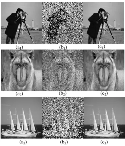
[image:4.595.319.558.247.434.2]images in terms of quantitative and qualitative metrics. Figure 6 shows the images which are used for training. Three different images are used in training, in order to improve the learning capability of neural network. The image shown in Figure 6(a1,2and3) are the noise free training image:
Baboonlion, cameraman and ship. The size of the each training image is 256 x 256. The images in Figure 6 (b1,2 and 3)
are the noisy training images and is obtained by corrupting the noise free training image by impulse noise of 45% noise density. The image in Figure 6(c1,2 and 3) are the trained images
[image:5.595.59.277.190.445.2]by neural network.
Figure 6 Performance of Training image: (a1,2 and 3)
original images, (b1,2 and 3) images corrupted with 45% of
noise and (c1, 2 and 3) trained images
The images in Figure 6(b) and (a) are employed as the input and the target (desired) images during training, respectively. The parameters of this network are then iteratively tuned. Once the training of the neural network is completed, its internal parameters are fixed and the network is combined with the nonlinear filter output and the modified Canny Edge Detector output to construct the proposed Technique, as shown in Figure5.
2.5. Testing of unknown images using
trained structure of FAN network
The optimized architecture that exhibited the best performance for training with a three images with 196608 data’s in the input layer, single hidden layer with 15 neurons and one output layer. The network trained with 45% impulse noise shows superior performance for testing under various noise levels. Also, to ensure faster processing, only the corrupted pixels from test images are identified and processed by the optimized neural network structure. As the uncorrupted pixels do not require further processing, they are directly taken as the output. The chosen network has been extensively tested for several images with different level of impulse noise.
Figure 7 shows the exact procedure for taking corrupted data’s for testing the received image signals for post processing. In order to reduce the computation time in real time
implementation; from unknown images, the corrupted pixels (data’s) from noisy image, pixels from NFT output images corresponding to the pixel position of the corrupted pixels from noisy image and pixels from Modified Canny Edge Detector output images corresponding to the pixel position of the corrupted pixels from noisy image are only taken as input for optimized neural network structure for testing and noise free pixels from input are directly taken as output pixels.
Figure7 Testing of the images using optimized feed forward adaptive
The tested pixels are replaced in the same location on corrupted image instead of noisy pixels. The most distinctive feature of the proposed filter offers excellent line, edge, and fine detail preservation performance and also effectively removes impulse noise from the image.
2.5. Filtering of the Noisy Image
The noisy input image is processed by sliding the 3x3 filtering window on the image. This filtering window is considered for both the NFT and the edge detector. The window is started from the upper-left corner of the noisy input image, and moved rightwards and progressively downwards in a raster scanning fashion. For each filtering window, the nine pixels contained within the window of noisy image are first fed to the NFT and the edge detector in the structure. Next, the center pixel of the filtering window on noisy image, the outputs of the Nonlinear Filtered image and the Modified Canny Edge Detector output image are applied to the appropriate inputs of the neural network. Finally, the restored image is obtained at the output of this network.
Modified Canny
Edge Detector
output
Corrupted pixels extracted from Noisy
image
Pixels extracted from NFT corresponding
to the corrupted pixels position
on noisy image Noisy
Image for Testing
NFT
Uncorrupted pixels on
Noisy image
Enhanced Image
F
AN
Ne
two
rk
trai
n
ed
stru
ct
u
re
Enhanced Image pixels using FAN Network
(a1) (b1) (c1)
(a2) (b2) (c2)
(a3) (b3) (c3)
Pixels extracted from MCED corresponding
to the corrupted pixels position
3. RESULTS
The proposed filter discussed in the previous section is implemented. The performance of the proposed filtering technique for image quality enhancement is tested for various level impulse noise densities. Four images are tested with size of 256 x 256 including Baboon, Lena, Pepper and ship. All test images are 8-bit gray level images. The experimental images used in the simulations are generated by contaminating the original images by impulse noise with different level of noise density.
The experiments are especially designed to reveal the performances of the filters for different image properties and noise conditions. The performances of all filters are evaluated by using the peak signal-to-noise ratio (PSNR) criterion, which is defined as
2
10
255
10 log
PSNR
MSE
(3)where
1 2
( ( , ) ( , ) 1 1
M N
MSE x i j y i j
i j
MN
(4)
Here, M and N represents the number of rows and column of the image and
x i j
( , )
andy i j
( , )
represents the original and the restored versions of a corrupted test image, respectively. Since all experiments are related with impulse noise. The experimental procedure to evaluate the performance of a proposed filter is as follows: The noise density is varied from 10% to 90% with 10% increments. For each noise density step, the four test images are corrupted by impulse noise with that noise density. This produces four different experimental images, each having the same noise density. These images are restored by using the operator under experiment, and the PSNR values are calculated for the restored output images. This produces ten different PSNR values representing the filtering performance of that operator for different image properties. This procedure is separately repeated for all noise densities from 10% to 90% to obtain the variation of the average PSNR value of that proposed filter as a function of noise density.An existing experimented median filter and their variations have a number of tuning parameters. This tuning parameter is nothing but fixed threshold value (T). This threshold value is selected based on filtering algorithm and the range of T decided by intensity of image 0 and 255 respectively. However, this T is suitable only for particular filtering algorithm. Unfortunately, there is no analytical method to determine the optimal values for these parameters that yield the best results for a given filtering experiment. Hence, the values of these parameters are heuristically determined and experimentally verified for each individual simulation experiment.
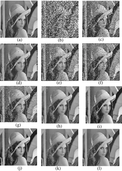
The filtered Lena image is presented in Figure 8 for visual perception and subjective evaluation. The values of objective measures obtained by applying the different filtering schemes, namely, Median Filter(MF), Weighted Median Filter (WMF), Center Median Filter (CWMF), Tri State Median Filter (TSMF), Multiple Decision Based Switching Median Filter (MDBSMF)[14], New Impulse Detector (NID), Decision
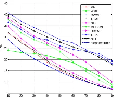
[image:6.595.316.553.168.499.2]Based Switching Median Filter (DBSMF)[21], Improved Decision Based Algorithm (IDBA) and the Nonlinear Filtering Technique (NFT) [23] and the proposed filter on Lena test image contaminated with the impulse noise of various densities are summarized in Table1 and is graphically illustrated in Figure.9 for quantitative metrics for different filtering techniques and compared with the proposed filtering technique. The proposed filtering technique outperforms the other filtering schemes for the noise densities up to 50%.
Figure 8 Performance of Test image: Lena (a) Noise free images, (b) image corrupted by 50% impulse noise, (c) images restored by MF, (d) images restored by WMF, (e) images restored by CWMF, (f) images restored by TSMF, (g) images restored by MDBSMF, (h) images
restored by NID, (i) images restored by DBSMF, (j)images restored by IDBA, (k) images restored
[image:6.595.69.281.257.346.2]by NNFT, (l) Proposed filter
Table 1 Performance of PSNR for different filtering techniques on Lena image
Filtering Techniques
Noise Level in %
10 20 30 40 50 60 70 80 90
MF 31.74 28.23 23.20 18.80 15.28 12.41 9.98 8.24 6.58 WMF 23.97 23.06 22.58 21.65 20.11 18.55 15.73 12.65 8.83 CWMF 28.72 23.80 20.28 17.28 14.45 11.96 10.04 8.24 6.75 TSMF 31.89 27.35 23.96 19.46 15.82 12.93 10.33 8.11 6.58 MDBSMFS 34.83 30.03 24.79 20.59 16.99 13.92 11.28 8.89 6.97 NID 37.90 31.85 28.75 26.52 23.42 18.89 14.65 10.83 7.77 DBSMF 38.42 34.28 30.47 27.38 24.92 22.05 18.84 14.12 10.03
IDBA 36.5 33.39 29.72 28.64 26 24.40 23.5 22.64 19.3 NFT 39.30 35.66 32.70 30.01 27.73 25.50 23.73 21.01 17.69 Proposed
filter 40.75 37.02 34.11 31.71 28.77 27.26 24.24 21.81 18.07
(a) (b) (c)
(d) (e) (f)
(g) (i)
(j)
(h)
10 20 30 40 50 60 70 80 90 5
10 15 20 25 30 35 40 45
Noise percentage
P
S
N
R
[image:7.595.70.267.72.244.2]MF WMF CWMF TSMF NID MDBSMF DBSMF IDBA NFT proposed filter
[image:7.595.332.534.180.526.2]Figure 9 PSNR obtained using proposed NBPPFT and compared with different filtering techniques on Lena image corrupted with different densities of impulse noise.
Figure 10 Performance of test images: (a1,2 and 3) original
images, (b1,2 and 3) images corrupted with 45% of noise,
(c1, 2 and 3) images restored by NFT and (d1, 2 and 3) images
enhanced by NBPPFT
Figure 10 presents four different the noise-free, noisy, and four filtered images for subjective evaluation. These test images corrupted with 50% impulse noise are used to illustrate the efficacy of the proposed filtering technique. The proposed filtering technique on different test images contaminated with the impulse noise of various densities is summarized in Table II. This proposed filter is found to have eliminated the impulse noise completely while preserving the image features quite satisfactorily. Figure11 graphically illustrates the performance of proposed filtering technique on
different test images in terms of PSNR contaminated with noise densities up to 90%. The newly proposed filter outperforms the other filtering schemes for the noise densities up to 50%. The proposed filtering technique is found to have eliminated the impulse noise completely while preserving the image features quite satisfactorily.
Table 2. PSNR values obtained by applying proposed filtering technique on different test images corrupted with
various densities of impulse noise
Noise Level in %
Images Name
BABOON LENA PEPPER RICE
10 35.7910 40.7560 44.1984 40.6098 20 32.1867 37.0278 40.3388 37.0517 30 29.7948 34.1111 37.2866 34.4746 40 28.0199 31.7107 34.6845 31.8580 50 26.4462 28.7732 32.5451 29.4475 60 24.9449 27.2644 29.6651 27.2788 70 23.4357 24.2457 27.0476 24.2598 80 21.7024 21.8062 24.0130 21.5350 90 19.6870 18.0764 19.7803 17.8376
10 20 30 40 50 60 70 80 90
15 20 25 30 35 40 45
Noise percentage
P
S
N
R
Baboon Lena Pepper Rice
Figure 11 PSNR obtained by applying proposed filter technique for different images corrupted with various
densities of mixed impulse noise
The proposed filter can be used as a powerful tool for efficient removal of impulse noise from digital images without distorting the useful information in the image. It can be seen that the proposed filtered images are more pleasant for visual perception.
Further, it can be observed that the proposed filter for image quality enhancement is better in preserving the edges and fine details than the other existing filtering algorithm. The advantages of the newly proposed filter may be summarized as follows:
1) It has a very simple structure. It is constructed by appropriately combining a NF filter, modified canny edge detector and a NF network. The structure of the neural network is also very simple.
(a1) (b1) (c1)
(a2) (b2) (c2)
(a3) (b3) (c3)
[image:7.595.68.266.300.607.2]2) It does not require user-supplied heuristic tuning parameters. The internal parameter of the proposed operator is adaptively tuned by training.
3) The training is easily accomplished by using very simple images. However, contrary to its simplicity in implementation and convenience in training, the proposed operator may be used for efficiently filtering any image corrupted by impulse noise of virtually any noise density.
It is concluded that the proposed filtering technique can be used as a powerful tool for efficient removal of impulse noise from digital images without distorting the useful information within the image.
4. CONCLUSION
A new Neural Based Post Processing Filter Technique (NBPPFT) is described in this paper. This filter is seen to be quite effective in eliminating the impulse noise; in addition, it preserves the image boundaries and fine details satisfactorily. The efficacy of the proposed filter is illustrated by applying the filter on various test images contaminated by different levels of noise. This filter outperforms the existing median based filter in terms of qualitative and quantitative measures. In addition, the proposed filter output images are found to be pleasant for visual perception, since the filter is robust against the impulse noise while preserving the image features intact. Further, the proposed filter is suitable for real-time implementation, and applications because of its adaptive in nature.
5. REFERENCES
[1] J. Astola and P. Kuosmanen. 1997. Fundamentals of Nonlinear Digital Filtering. New York: CRC.
[2] I. Pitas and A. N. Venetsanooulos. 1990. Nonlinear Digital Filters: Principles Applications. Boston, MA: Kluwer.
[3] T.Chen, K.-K.Ma, and L.- H. Chen, “Tri state median filter for image denoising,” IEEE Trans.Image Process., 1994, vol.8, no.12, pp.1834-1838.
[4] T.Sun and Y.Neuvo, “Detail preserving median filters in image processing,” Pattern Recognition Lett., 1994, vol. 15, pp.341-347.
[5] Zhang and M.- A. Karim, “A new impulse detector for switching median filters”, IEEE Signal Process. Lett., (Nov. 2002), vol. 9, no. 11, pp. 360–363.
[6] M. Barni, V. Cappellini, and A. Mecocci, “Fast vector median filter based on Euclidian norm approximation”, IEEE Signal Process. Lett., vol.1, no. 6, pp. 92– 94, Jun. 1994.
[7] Z. Wang and D. Zhang, “Switching median filter for the removal of impulse noise from highly corrupted images”, IEEE Trans. Circuits Syst. II, (Jan. 2002), vol.46, pp.78–80.
[8] E.Abreu, M.Lightstone, S.K.Mitra, and K. Arakawa, “A new efficient approach for the removal of impulse noise from highly corrupted images”, IEEE Trans. Image Processing, 1996, vol. 5, pp. 1012–1025.
[9] H.-L. Eng and K.-K. Ma, “Noise adaptive soft – switching median filter,” IEEE Trans. Image Processing, (Feb. 2001), vol. 10, pp. 242–251.
[10]Sebastian hoyos and Yinbo Li Weighted, “ Median Filters Admitting Complex -Valued Weights and their Optimization”, IEEE transactions on Signal Processing, (Oct. 2004)Vol.52, no.10.
[11]Pei - Eng Ng and Kai - Kuang Ma, “A Switching median filter with boundary Discriminative noise detection for extremely corrupted images”, IEEE Transactions on image Processing, (June.2006),vol.15, no.6, pp.1500-1516.
[12]Tzu – Chao Lin and Pao - Ta Yu, “salt –Pepper Impulse noise detection”, Journal of Information science and engineering, (June. 2007), vol.4, pp189-198.
[13]E.Srinivasan and R.Pushpavalli, “ Multiple Thresholds Switching Median Filtering for Eliminating Impulse Noise in Images”, International conference on Signal Processing, (Aug. 2007), CIT. .
[14]R.Pushpavalli and E.Srinivasan, “Multiple Decision Based Switching Median Filtering For Eliminating Impulse Noise with Edge and Fine Detail preservation Properties”, International conference on Signal Processing,(Aug.2007) CIT.
[15]Yan Zhouand Quan-huanTang, “Adaptive Fuzzy Median Filter for Images Corrupted by Impulse Noise”, Congress on image and signal processing,2008.
[16]Shakair Kaisar and Jubayer AI Mahmud, “ Salt and Pepper Noise Detection and removal by Tolerance based selective Arithmetic Mean Filtering Technique for image restoration”, IJCSNS, (June, 2008),Vol.8, No.6.
[17]T. C. Lin and P.T. Yu, “Adaptive two - pass median filter based on support vector machine for image restoration ”, Neural Computation, 2004, Vol. 16, pp.333-354.
[18]Madhu S.Nair, K.Revathy, RaoTatavarti, "An Improved Decision Based Algorithm For Impulse Noise Removal", Proceedings of International Congress on Image and Signal Processing - CISP 2008, IEEE Computer Society Press, (May 2008), Sanya, Hainan, China, Vol.1, pp.426-431,.
[19]V. Jayaraj and D. Ebenezer , “A New Adaptive Decision Based Robust Statistics Estimation Filter for High Density Impulse Noise in Images and Videos”, International conference on Control, Automation, Communication and Energy conversion, 2009.
[21]R.Pushpavalli and E.Srinivasan, “Decision based Switching Median Filtering Technique for Image Denoising”, CiiT International journal of Digital Image Processing, (Oct.2010), Vol.2, no.10, pp.405-410.
[22]R.Pushpavalli, E.Srinivasan and S.Himavathi, “A New Nonlinear Filtering technique”, 2010 International Conference on Advances in Recent Technologies in Communication and Computing, Oct.16, 2010, ACEEE.
[23]Bao, P. Lei Zhang Xiaolin Wu , “Canny edge detection enhancement by scale multiplication”, IEEE Transactions on Pattern Analysis and Machine Intelligence, 2005, vol. 27, no.9, pp.1485 – 1490.
[24]M. Emin Yüksel, “A Hybrid Neuro – Fuzzy Filter for Edge Preserving Restoration of Images Corrupted by Impulse Noise”, IEEE transactions on image processing, (April 2006), Vol. 15, No. 4,.
[25]Pinar Civicioglu, “Using Uncorrupted Neighborhoods pixels for Impulsive Noise Suppression With ANFIS", IEEE transactions on image processing, (March 2007), Vol.16, No.3, pp.759-773.
[26]Chen Jindu and Ding Runtao Ding, “A Feed forward neural Network for Image processing”, in IEEE proceedings of ICSP, 1996, pp.1477-1480.
[27]Wei Qian, Huaidong Li, Maria Kallergi, Dansheng Song and Laurence P. Clarke, “Adaptive Neural Network for Nuclear Medicine Image Restoration”, Journal of VLSI Signal Processing, 1998, vol. 18, 297–315, Kluwer Academic Publishers.