An Encryption Algorithm for End-to-End Secure Data
Transmission in MANET
Rohan Rayarikar
Masters in Science (M.S.)
Computer Science
Northeastern University, Boston,
MA
Ajinkya Bokil
Masters in Science (M.S.)
Computer Science
Northeastern University, Boston,
MA
ABSTRACT
Encryption is of prime importance when confidential data is transmitted over wireless network. Numerous encryption algorithms like AES, DES, RC4 and others are available for the same. The most widely accepted algorithm is AES algorithm. We have proposed a new algorithm based on the concept used by Rijmen and Daemen (Rijndael algorithm), the founders of AES algorithm. The proposed algorithm encrypts and decrypts two 128 bits data simultaneously i.e. 256 bits data, thus providing strong encryption accompanied with complex processing. The proposed Feistal algorithm uses various invertible, self-invertible, and non-invertible components of modern encryption ciphers and key generation same as that of AES. This algorithm provides a secure, fast, and strong encryption of the data. There is a huge amount of confusion and diffusion of the data during encryption which makes it very difficult for an attacker to interpret the encryption pattern and the plain text form of the encrypted data. The proposed algorithm is also resistant to Brute-Force and pattern attacks. This algorithm proves particularly useful while transmitting confidential data over a Bluetooth or wifi network. This algorithm is implemented in the Application layer of the device. The details of implementation are given in the article.
General Terms
Security Algorithm, Symmetric Key Encryption, MANET.
Keywords
Encryption Algorithm, Matrix Transformation, Complement, Feistal, Dynamic Row Modification, Row Column Swapping.
1.
INTRODUCTION
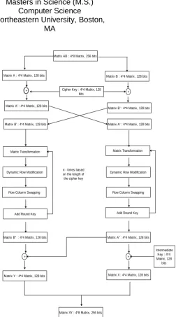
[image:1.595.313.566.146.600.2]A Mobile Ad-Hoc Network (MANET) is a self-configuring infrastructure-less network of mobile devices connected wirelessly. Various devices are connected wirelessly on MANET and transmit data to one another. Since, the devices are mobile; they change their links to other devices frequently. Each device should be able to act like a router. Since the devices are connected wirelessly; it is very easy for the intruder to get hold of the data. [6] The proposed algorithm increases the data confidentiality by confusion, diffusion and encryption of data.The proposed algorithm is to be implemented in the application layer.The algorithm is explained below.
Figure 1: Flowchart of proposed algorithm
2.
THE
PROPOSED
ALGORITHM
The proposed algorithm is an asymmetric key encryption algorithm. It uses Rjindael’s key generation algorithm for generation of the round key. Based on the length of the cipher key; 10, 12 or 14 round keys are generated. The input to the algorithm is a 4*8 matrix. This matrix is then split into two separate 4*4 matrices. The reason behind taking a large even numbered matrix is that more data can be encrypted in less amount of time. [5] The two matrices; for ease of understanding lets name them A and B; are processed
Matrix AB : 4*8 Matrix, 256 bits
Matrix A : 4*4 Matrix, 128 bits Matrix B : 4*4 Matrix, 128 bits
Matrix A' : 4*4 Matrix, 128 bits Matrix B' : 4*4 Matrix, 128 bits Matrix A' : 4*4 Matrix, 128 bits
Cipher Key : 4*4 Matrix, 128 bits
Matrix B' : 4*4 Matrix, 128 bits
Add Round Key Row Column Swapping Dynamic Row Modification
Matrix Transformation
Add Round Key Row Column Swapping Dynamic Row Modification
Matrix Transformation
+ +
Matrix B'' : 4*4 Matrix, 128 bits Matrix A'' : 4*4 Matrix, 128 bits
Matrix Y : 4*4 Matrix, 128 bits
Intermediate Key : 4*4 Matrix, 128
bits Matrix X : 4*4 Matrix, 128 bits
+ +
simultaneously. The flowchart for the algorithm is shown in figure1.
2.1 Initial Processing
The matrices A and B are both 4*4 matrices of 32 bits. A 4*4 cipher key is xor-ed with both A and B. The cipher key is either taken from the user or is auto-generated based on the choice of the user. Let us consider A’ and B’ being obtained from A and B respectively. A’ and B’ are then swapped with each other. This completes the initial processing of the data. [4]
2.2 Steps in Encryption Process
2.2.1 Dynamic Row Modification
In this step, first row of the data matrix is selected for modification decisions. All elements of the first row are XORed to get one 8-bit number (say PP’) which can be split as two 4-bit numbers (say X and Y). [2] One element (say EE’) which is to be XORed with the row to be modified will be taken from the data matrix. Row number of EE’ will be given by 2 LSBs of X and column number of EE’ will be given by 2 LSBs of Y. [2] Row to be modified is decided by calculating (number of 1s in PP’%4). Each element of this row is XORed with EE’ to get the required modified row in the data matrix.
2.2.2 Matrix Transformation
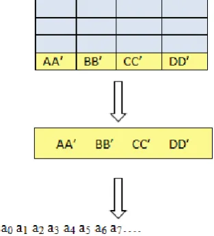
In matrix transformation, each row is modified separately based on predefined condition. Each row is converted to binary equivalent as shown in figure 2.
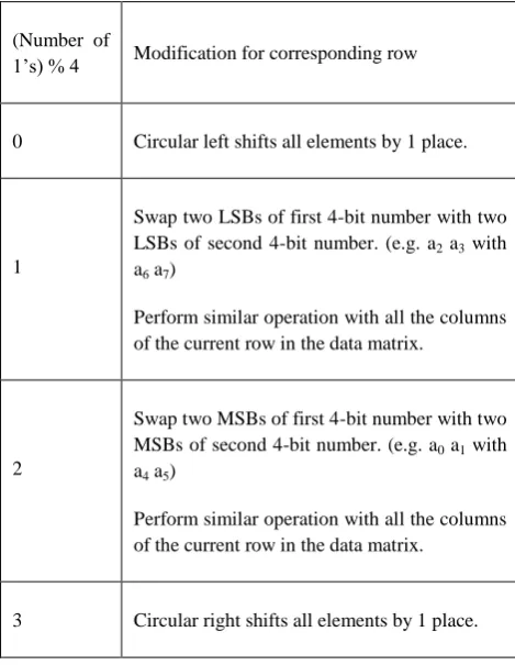
[image:2.595.311.547.70.362.2]After computing the binary equivalent of particular row; number of 1s in the result is calculated. The condition for modification is calculated as number of 1s % 4. Based on the output, the changes are made as per table 1.
Figure 2: Calculating binary equivalent for Matrix Transformation
(Number of
1’s )% 4 Modification for corresponding row
0
Circular right shifts all elements by 1 place.
1
Swap two LSBs of first 4-bit number with two LSBs of second 4-bit number.
(e.g. a2 a3 with a6 a7)
Perform similar operation with all the columns of the current row in the data matrix.
2
Swap two MSBs of first 4-bit number with two MSBs of second 4-bit number.
(e.g. a0 a1 with a4 a5)
Perform similar operation with all the columns of the current row in the data matrix.
[image:2.595.66.223.478.651.2]3 Circular left shifts all elements by 1 place.
Table 1: Modification Table for Matrix Transformation
2.2.3 Row Column Swapping
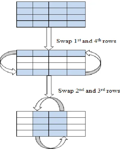
In row column swapping, all the elements of the data matrix are XORed. Number of 1s in the result is calculated after which (Number of 1s % 4) is computed. Based on the result, data matrix is modified according to the following table.
Number of 1s % 4
Row swapping Column Swapping
0 1 and 4 2 and 3
1 2 and 3 1 and 4
2 1 and 2 3 and 4
3 3 and 4 1 and 2
Table 2: Row Column Swapping
Figure 3: Example of Row Column Swapping
2.2.4 Add Round Key
This is the last step of the rounds of encryption process. In this step the round key generated using the key scheduling algorithm is XOR-ed with the matrix given input to this step. The key is arranged in a 4*4 matrix. [2] The XOR operation takes place column-wise i.e. first column of round key matrix is XOR-ed with the first column of the inputted matrix. For every round a new round key is generated. For a particular round, same round key is used to encrypt both left and right 4*4 parts of the data matrix. [1]
2.3 Steps in Decryption Process
2.3.1 Inverse Dynamic Row Modification
This step is same as the dynamic row modification in encryption process. In this step, first row of the data matrix is selected for modification decisions. All elements of the first row are XORed to get one 8-bit number (say PP’) which can be split as two 4-bit numbers (say X and Y). One element (say EE’) which is to be XORed with the row to be modified, will be taken from the data matrix. Row number of EE’ will be given by 2 LSBs of X and column number of EE’ will be given by 2 LSBs of Y. Row to be modified is decided by calculating (number of 1s in PP’%4). Each element of this row is XORed with EE’ to get the required modified row in the data matrix.2.3.2 Inverse Matrix Transformation
[image:3.595.338.516.75.244.2]This step is same as Matrix Transformation in Encryption process with some minor changes in modification table. In matrix transformation, each row is modified separately based on predefined condition. [4] Each row is converted to binary equivalent as shown in figure.
Figure 4: Calculating binary equivalent for Matrix Transformation
After computing the binary equivalent of particular row; number of 1s in the result is calculated. The condition for modification is calculated as number of 1s % 4. Based on the output, the changes are made as per the following table.
(Number of
1’s) % 4 Modification for corresponding row
0 Circular left shifts all elements by 1 place.
1
Swap two LSBs of first 4-bit number with two LSBs of second 4-bit number. (e.g. a2 a3 with
a6 a7)
Perform similar operation with all the columns of the current row in the data matrix.
2
Swap two MSBs of first 4-bit number with two MSBs of second 4-bit number. (e.g. a0 a1 with
a4 a5)
Perform similar operation with all the columns of the current row in the data matrix.
3 Circular right shifts all elements by 1 place.
Table 3: Modification Table for Matrix Transformation
2.3.3 Inverse Row Column Swapping
[image:3.595.310.545.362.665.2](Number of 1s) % 4
Row swapping Column Swapping
0 1 and 4 2 and 3
1 2 and 3 1 and 4
2 1 and 2 3 and 4
[image:4.595.50.281.70.264.2]3 3 and 4 1 and 2
Table 4: Row Column Swapping
For example, suppose after XORing all the elements, (Number of 1s % 4) is 0, following operations will take place.
2.3.4 Add Round Key
This is the last step of the rounds of decryption process. In this step the round key generated using the key scheduling algorithm is XOR-ed with the matrix given input to this step. The key is arranged in a 4*4 matrix. The XOR operation takes place column-wise i.e. first column of round key matrix is XOR-ed with the first column of the inputted matrix. For every round a new round key is generated. For a particular round, same round key is used to encrypt both left and right 4*4 parts of the data matrix. The round keys used for decryption are in opposite direction as that of encryption. For example, nth round key is used for nth round in case of encryption where as in case of decryption it is used for first round.
Figure 5: Example of Row Column Swapping
3.IMPLEMENTATION
The proposed algorithm can be implemented in any language. This algorithm can also be used in general data encryption. We have implemented it in java, java being an open source and platform independent language. The pseudo codes for the components of the cipher are given below. The entire codes are not written for obvious reasons.
3.1 Add Round key:
public byte[ ][ ] addRoundKey(byte[ ][ ] state,byte[ ][ ] roundkey)
{
for (int i=0;i<4;i++) {
for (int j=0;j<4;j++) {
state [i][j]=doExclusiveOR(state[i][j], roundkey[i][j]);
} }
return state; }
3.2 Dynamic Row Modification
public String[][] Dynamic_Row_Modification (String[][] ip) {
Integer object; for (j=0; j<length; j++) {
do{
x=XOR(ip[0][j], ip[0][j+1]; } while (j<4)
}
y=NoOfOnes (x[i][j])%4; Row_no=firstTwoLSB[x]; Column_no=TwoBits[x];
Element=ip[Row_no][Column_no]; for (j=0; j<length; j++)
{
ip[y][j]=XOR(ip[y][j], element); }
return ip; }
3.3 Matrix Transformation
public String[][] Matrix_transform (String[ ][ ] ip) {
n= integer object; for (i=0; i<length; i++) {
Int row=ip[i];
for (j=0; j<length; j++) {
Int bin[i][j]=BinEq(ip[i][j]); n=NoOfOne (bin[i][j]); }
} x=n%4;
if(x==0){Circular_Right_Shift(bin[i][j]);} else if(x==1){SwapLSB (bin[i][j]);} else if(x==2){SwapMSB(bin[i][j]);} else if(x==3){Circular_Left_Shift(bin[i][j]);} return bin;
[image:4.595.63.265.463.714.2]3.4 Row Column Swapping
public String[][] Row_Column_Swapping(String[ ][ ] ip) {
for (i=0; i<length; i++) {
for (j=0; j<length; j++) {
X=XOR(string[ ][ ] ip) }
}
if((X%4)==0){Swap 1423(String[ ][ ] ip)} else if((X%4)==1){Swap 2314(String[ ][ ] ip)} else if((X%4)==2){Swap 1234(String[ ][ ] ip)} else if((X%4)==3){Swap 3412(String[ ][ ] ip)} return ip;
}
4. STRENGTH OF THE ALGORITHM
The cipher key used in the proposed algorithm is of 128 bits. Therefore, to break the cipher key an attacker has to check 2128 possibilities which are practically almost impossible. Therefore, the Brute-force Attack fails on this algorithm. [4] The flow of the algorithm makes sure that there is no fixed pattern in any of the steps of the algorithm. The components of the proposed algorithm have brought about strong diffusion and confusion. Therefore, statistical and pattern analysis of the ciphertext fails. [4]
The algorithm turns into a Feistal structure cause of various swapping operations performed. [4]
Another most important security advantage is that no
differential or linear attacks can break this algorithm. [4]
5. CONCLUSION
As discussed in the paper, Mobile ad-hoc network is a less secure means of transmitting data from one device to the other within a wireless network. An attacker with basic knowledge of hacking into systems can easily procure the data being transferred. The proposed encryption algorithm, implemented in application layer, tries to avoid this possibility. The
algorithm enhances the security of data by confusion and diffusion. Since the algorithm can also be implemented on a mobile device, care has been taken that it consumes minimum resources of the processor, thus enhancing the efficiency of the device. The security of end-to-end data transmission in MANET is improved when the proposed algorithm is used.
6. REFERENCES
[1] J.Daemen and V.Rijmen, AES Proposal: Rijndael, NIST’s AES home page, http ://www:nist:gov/aes. [2] “Announcing the Advanced Encryption Standard
(AES)”, Federal Information Processing Standards Publication 197, November 2001
[3] Priyanka Pimpale, Rohan Rayarikar and Sanket Upadhyay, “Modifications to AES Algorithm for Complex Encryption”, IJCSNS International Journal of Computer Science and Network Security, VOL.11 No.10, October 2011.
[4] Rohan Rayarikar, Sanket Upadhyay, Deeshen Shah “An Encryption Algorithm for Secure Data Transmission”, IJCSNS International Journal of Computer Application, VOL.40 No.7, February 2012.
[5] Sakib, Rizwanul Karim; Reza, Bisway “Security Issues in VANET” BRAC University Institutional Reposistory, April 2010
[6] Brent A. Peacock “CONNECTING THE EDGE: Mobile Ad-Hoc Networks (MANETs) for Network Centric Warfare” Blue Horizons Paper, Center for Strategy and Technology, Air War College, April 2007