2018 International Conference on Modeling, Simulation and Analysis (ICMSA 2018) ISBN: 978-1-60595-544-5
Modular Simulation Design of Human-machine Interaction for Civil
Aircraft Cockpit
Zheng LIU
*, Fei LI and Xiao-ying NIU
Shanghai Aircraft Design and Research Institute, Cockpit Integration and Industrial Design Research Department, Shanghai 201210, China
*Corresponding author
Keywords: Model-based design, Human machine interaction, Cockpit evaluation, Software engineering, Human in the loop.
Abstract. A design method for human-machine interaction (HMI) simulation of the civil aircraft cockpit has been introduced, including model-based design of user interface, logic dependency of control panel and display, and warning conditions under various scenarios. The civil aircraft cockpit HMI simulation can be used for cockpit layout, static and dynamic evaluation of flight tasks, and dynamic assessment platform. Additionally, the modular design has the advantages of flexible modification, cost saving, and quick access to the user’s requirement. Finally, a prototype of high lift system (HLS) of the civil aircraft has been used to illustrate the cockpit HMI simulation with the slat-flap retraction and extraction process.
Introduction
The human machine interaction is a dynamic process of the flight crew members (users) and the aircraft (computer) communication. The user manipulates the computer as input, and the computer receives keyboard and switch signals, and then feeds back information to users through visual, auditory or tactile forms. The cockpit is the main way to communicate with airplanes for the flight crew members. It provides information for pilots such as aircraft status, navigation information, air temperature and cabin pressure and so on. [1, 2]. The pilot can also accomplish different flight missions, such as take-off, landing, tower communication, and cabin temperature modification, through manipulating devices in the cockpit [2]. Therefore, the rational design of the cockpit has played a key role in completing flight tasks, ensuring flight safety and providing flight information.
With the development of information technology, the Computer Aided Engineering (CAE) is possible for the cockpit simulation. The computer can simulate the control panel, display and alarm in the cockpit, as well as the terrain, weather and the other scenes outside. In different flight phases, the posture, external view and working mode of each subsystem can also reconstruct [3] by computer. The application of computer technology in the field of the flight simulator provides the basis and support for the human-computer interaction of the cockpit.
Interactive Simulation of Cockpit Human-machine Interface
The cockpit human-machine interaction simulation is based on the computer as the main auxiliary means, with which user can interact with the environment by means of software and hardware to meet the ergonomics requirement. In addition, it can provide a dynamic platform for the engineer and the flight crew members and give a feasible way for the cockpit integration.
repeatedly, can we deliver a satisfied product [4, 5]. The modular design provides an effective solution to meet the flexible requirements of the product and the modification at different stages, which facilitates the cockpit design, especially the display layout.
The evaluation of cockpit design is an important phase of the aircraft design process. According to the airworthiness regulations (CCAR25-R4 [6], FAR25, and CS25) and industry standard documents (SAE ARP files [7, 8], etc.), the evaluation system has seven first level indicators [4, 5]:
a) Overall function: To evaluate the function definition, necessity, consistency, and failure mode and so on from the overall function of the device.
b) Label: the consistency of the device and function is evaluated from the label of the device. c) Multiple control interaction: if multiple functions exist, whether the device matches the
function of multiple controllers.
d) Accessibility: the accessibility of the device under the normal and abnormal conditions. e) Environmental impact: operation in normal and abnormal environment, such as low visibility,
turbulence, smoke and other environments.
f) Compatibility of controller and display: the convenience of the device operation, interference with the flight tasks, etc.
g) Proper feedback: check whether the operation of the input is valid or not.
The listed two indicators of the overall function and the label can be judged by the form of static graphic and text to judge whether they are in accordance with the rules. For example, multiple control interaction, compatibility of control and display and appropriate feedback and other indicators need to be identified through the dynamic process. The human-machine interaction can help to understand intuitively the design rationality and put forward evaluation opinions and optimization plan [9].
Based on the challenges of the complex and changing design requirements and the evaluation rules above, the modular human-machine interaction simulation has become an important part of the cockpit design.
Research on Related Fields
Model based system engineering (MBSE) is the application of modeling method of system engineering activities for system requirements, design, analysis, verification and validation activities, which is started from the conceptual design throughout all the design development stages of the product life cycle [10]. Compared with the traditional design method, model-based system engineering is intuitive, modularized, and reusable and so on. Therefore, it is widely applied in software engineering, automotive electronics and other related fields, [11].
For the civil aircraft design, the modeling and simulation has also played an important role. The model based system engineering can support the V&V (Verification and Validation) process. In the design phases of the V&V process, the system architect can make the aircraft design with good trace-ability through the modeling design method [12]. The modular design of the civil aircraft system ensures the test-ability, sustainability, and functional integrity of the whole process [14]. In addition, for a single subsystem, such as Flight Management System (FMS), the system structure is complex and involves data linked with the other multiple systems. The modular simulation method can decompose the complex system into details and finish the related functions of flight management more effectively [16].
The following section describes a design method of the model-based human-computer interaction and provides a prototype of an aircraft wing HMI simulation, for reference.
System Architecture
operate the devices through the user interface and the expert make an assessment (see Figure 1, User / Expert).
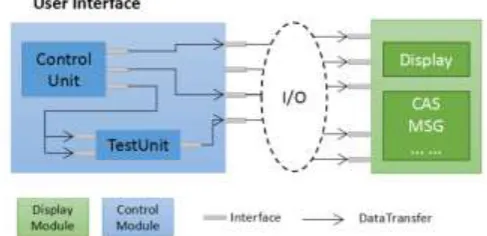
The user interface on the front desk is the main way for users to communicate with computers, including images, audio, and video (see Figure 1, User Interface). They transfer the system status to the user through visual, auditory, and tactile forms. The carrier of the message is encapsulated into an independent module that is used for the user/expert to do assessment. For example, should alarm information be notified to the user by red light or voice reminding?
The user's control input and system output are linked with the system model through the back-end logic (see Figure 1, Logic Control). The control logic part in the background includes the state machine, the program design and the logical judgment, etc. The control logic is defined according to the needs of system interaction. For example, when speed is greater than a critical value, it reminds pilots to reload landing gear, status changes of the function modes under different working conditions, and prioritize alarm information.
[image:3.595.183.414.326.468.2]The human-computer interaction is concerned with the interaction process of the user and the system instead of the realization of the system function. The system model (see Figure 1, System Model) can be a black box. The system architecture does not need to know the internal structure of each module, which only needs to know the functions of modules and the interface requirements.
Figure 1. HMI system architecture.
System Architecture
Modular Human-machine Interface Design
The modular design of cockpit human-machine interface uses the idea of composite pattern, that is, the module is made up of different design elements, and the module itself can also be used as the design element for different cockpit configurations. The modules are encapsulated as a whole and provide standardized interfaces. On one hand, they are convenient for the module replacement, and on the other hand, they are efficient for testing the single modules or subsystems. Figure 2 makes a simple functional division of the cockpit user interface.
[image:3.595.174.418.639.757.2] The blue box on the left side represents the control module, including control unit (see Figure 2, Control Unit), test unit (see Figure 2, Test Unit) and interface (see Figure 2, Interface). The control unit is a number of control devices, such as buttons, knobs, switches, keyboards and so on. Engineers can set faults to determine whether the alarm is in line with the requirements. To improve the efficiency of development, re-usability is also needed to be considered through data transfer between and within the modules.
The right green box shows the display module, including display unit (see Figure 2, Display Unit), alarm information (see Figure 2, CAS MSG) and interface (see Figure 2, Interface). The display unit and alarm information provide the user the information of system status, parameter information, display and voice alarm.
In addition, the signal is the unidirectional mapping, which means one termination point cannot be associated with two or more than two starting points (see Figure 2, Data Transfer). The signal can be cross-linked with other modules through the module interface, or through the I/O interface (see Figure 2, I/O), and the other logic control part.
Logic of Human-machine Interaction
The control and display module of the human-machine interface are linked through the interface of the control part to realize the simulation design of human in the loop. The input interface of the control part includes the user’s instruction and the test signals, and the output displays the state information of the system model.
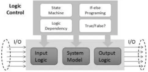
Logic control should be designed separately from the system model (see Figure 3, System Model) to achieve the purpose of modifying the logic without affecting the system model. The input back-end logic (see Figure 3, Input Logic) focuses on the interaction between a person and a control device, for example, the trigger condition of activating system's function. Output logic (see Figure 3, Output Logic) focuses on how to feedback system information to people, such as when and where to display information and alarm message effectively. In addition, human computer interaction focuses on the human instead of the system function as the center. The system performance, response time, output curve and so on are not considered in the design process.
[image:4.595.176.419.511.630.2]The logic control can be such as state machine, if-else programming, logic dependency, and True/False logical judgments and so on, as shown in Figure 3.
Figure 3. Logic control of human machine interface.
A Design Prototype of High Lift System HMI
According to design method in the last part, this chapter introduces the HMI design prototype of the high lift system (HLS) for the civil aircraft. The front desk design uses a graphical software VAPS XT to realize [17, 18], and the logical control part is built with Matlab/Simulink.
Modular Design of Cockpit Human-machine Interface
SLATS). According to the different phases of flight, slat-flap handle position can be at 0, 1, 2, 3, FULL. The test unit simulates the working modes of the slat-flap system namely, normal mode, failure mode, downgrade mode and failure mode. The position and working mode of the handle are transferred to the control part as the input of the human-machine logic.
Figure 4. Cockpit pedestal panel.
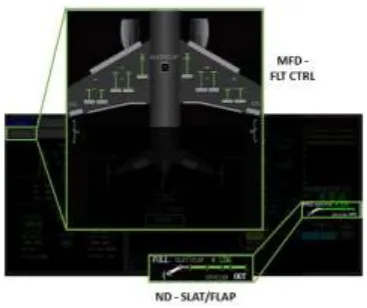
[image:5.595.203.387.420.574.2]A civil aircraft cockpit display screen includes primary flight display (PFD), navigation display (ND), multi-function display (MFD) and engine indication and crew alarming system display (EICAS Display). The status information of the aircraft is fed back to the user through the text, graphics, or video of the display screen. The navigation display and multi-function display interface, as shown in Figure 5, includes the flight control system schematic page (MFD - FLT CTRL), the position status of the wing (ND - SLAT/FLAP), and EICAS alarm etc.
Figure 5. ND, MFD and EICAS display.
Interactive Design of Slat-flap Retraction and Extraction Process
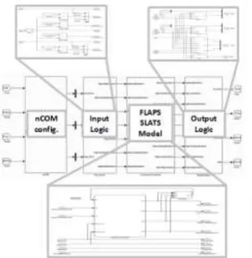
Figure 6 is a simple slat-flap system control model. The "nCOM config." in the image defines the configuration of related parameters, such as the data transfer frequency, the communication mode, and so on. The "Input Logic", "FLAPS SLATS Model" and "Output Logic" in figure 6 determinate the slat-flap input logic, system model and output logic. In this example, the system model is approximated as the first order transfer function. By changing the time parameters of transfer function, we can achieve the goals such as the slat retraction speed or the slat-flap semi-automatic mode.
Here list an example to show the input and output logic of the HLS separately:
Input logic: slat-flap device has a threshold in the 2 position, handle cannot be handled directly from the 1 position to 3 position;
Figure 6. Logic controls of slat-flap retraction and extraction.
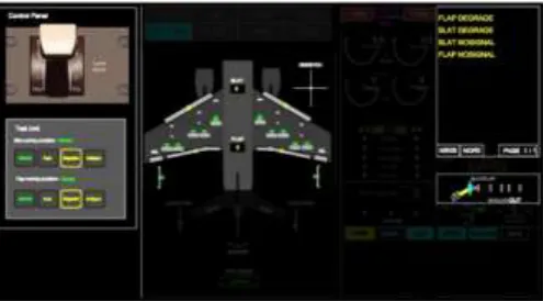
[image:6.595.172.425.357.492.2]Figure 7, figure 8, figure 9 and figure 10 represent the slat-flap control panel in normal, blocked/fault, failure/invalid and degradation of four working modes (on the left side) and displays (on the right side). User switches different working modes and determines whether the display or alarm is in line with the design requirements.
[image:6.595.173.423.518.657.2]Figure 7. Slat-flap retraction and extraction process HMI display (working mode: normal mode).
Figure 9. Slat-flap retraction and extraction process HMI display (working mode: invalid mode).
Figure 10. Slat-flap retraction and extraction process HMI display (working mode: degrade mode).
Summary
With the idea of modular design, this paper introduces a rapid prototyping method for the cockpit interaction design.
1) Modular human-machine interface design. The display element is edited as a single object and encapsulated as a separate design module for the purpose of different cockpit configurations. The focus is to display the attributes of the elements, function definitions, interfaces, and intern/extern relationships.
2) Logical control of the user’s operation. The display element is fed back to the user through the display of the state machine, flow chart, code programming. The focus is on the operation process, namely, where is the starting point, what is the function of the first step, and how does the state of the last point work, etc.
In the high lift system example, flap/slat model is used to simulate with the transfer function. However, the system model of the whole aircraft is very complex and involves different flight phases. Therefore, how to simulate and acquaint flight data, and how to drive the real-time display for the cockpit simulation; how to integrate each subsystem with the signal and the other related issues will be studied in the future research.
References
[1] Duan Lin. The evolution and development trendency of human-machine interface in cockpit [J]. Civil Aircraft Design and Research, 2017 (1): 7-11.
[2] Dong Dayong, Yu Jinhai, Li Baofeng, Chen Yingchun et al. Cockpit human factors of airworthiness verification technology [J]. Chinese Journal of Aeronautics, 2016, 37 (1): 310-316.
[image:7.595.175.423.234.371.2][4] Jin Zhefeng, Zhang Yinbo, Liu Haiyan. Design and research of civil aircraft cabin layout design method of civil aircraft [J]. Civil Aircraft Design and Research, 2017 (1): 12-16.
[5] Yuan Xiao, Hao Dongjing, Liu Haiyan, Jin Zhefeng, Dong Dayong. Civil aircraft cockpit evaluation of aircraft design and research method [J]. Civil Aircraft Design and Research, 2017 (1): 17-22.
[6] China Civil Aviation Administration 2nd China civil aviation regulations twenty-fifth: Transport Aircraft Airworthiness Standard [S]. China Civil Aviation Administration, 2001.
[7] SAE ARP 4754A. Guidelines for Development of Civil Aircraft and Systems
[8] SAE ARP 5056. Flight Crew Interface Consideration in the Flight Deck Design
[9] Xu Haiyu, Zhang an, Tang Zhili. Comprehensive evaluation of human computer interface in aircraft cockpit [J]. Science and Technology and Engineering, 201212 (4): 940-943.
[10] Wang Kang Sheng, Yuan Jianhua, Chen Hongtao and so on. Research and practice of system engineering methods based on modeling and simulation technology [J]. China Aerospace, 2012 (11): 52-57.
[11] Ren Xiao Wei, Zhang Wei. Research on the simulation method of using VAPS to evaluate aviation instrument, [J]. Human Ergonomics, 2011, 17 (1): 41-44.
[12] Zhu Jing, Yang Hui, Gao Yahui and so on. Model-based system engineering overview [J]. Aeroengine, 016, 42 (4): 12-16.
[13] Qiao Wenfeng, Li Zhengqiang, Huang Shuai et al. Research on model-based integrated design of civil aircraft [J]. Aeronautical Manufacturing Technology, 2015, 473 (4): 72-77.
[14] Ding Ding. Application of system engineering in the field of civil aircraft based on the modular design [J]. Journal of the Shenyang University of Aeronautics and Astronautics, 2012, 29 (4): 47-50.
[15] Li Qing. A new breakthrough in aircraft development technology – model-based system engineering [J]. Aeronautical Manufacturing Technology, 2011 (12): 48-53.
[16] Ma Cunbao, Zhu Chao, Wang Yansong. Modular simulation design of flight management system [J]. Industrial Instrumentation & Automation, 2014 (2): 42-45.
[17] Yang Weifeng, Hu Xiaoqin, Cai Zhiyong and so on. Simulation of multi-functional display based on VAPS design [J]. Computer Applications and Software, 2011, 28 (6): 228-229.