Preliminary analysis on generated jet pressure from ionic polymer composite
actuated radial contraction using balloon manometry technique
Muhammad Farid S.1, Samad Z.2, Husaini A.B.2,3, Arshad M.R.2 & Mahzan S.1
1Faculty of Mechanical and Manufacturing Engineering, Universiti Tun Hussein Onn Malaysia, 86400, Batu Pahat, Johor, Malaysia 2USM Robotics Research Group (URRG), School of Electrical and Electronic Engineering,
Universiti Sains Malaysia, 14300 Nibong Tebal, Pulau Pinang, Malaysia 3
Universiti Kuala Lumpur Malaysian Spanish Institute, 09000 Kulim, Kedah, Malaysia [E-mail: [email protected]]
Received 5 December 2012; revised 14 September 2013
Contractile thruster has become a trend for underwater robot propulsion because of its prospective and advantages. However, it is difficult to determine the performance of the generated jet pressure from the small thruster. Thus, in this research an analysis was carried out to observe the radial contraction effects on the jet pressure by applying balloon-manometry technique. Four Ionic Polymer-Metal Composite (IPMC) filament actuators had been utilized as the longitudinal artificial muscle. The lengths of the IPMC actuators were 30 mm, 40 mm and 50 mm. During actuation, the radial contraction differentiated the pressure in the cylindrical shape balloon which was measured by a gauge pressure transducer. The result shows that at 30 mm length, the obtained pressure was almost 0.01psi. The shorter IPMC actuator gave higher contraction force and propulsive pressure.
[Keywords: Jet pressure, Radial contraction, IPMC, Manometry]
Introduction
Currently, rotary-blade propeller is widely used as a thruster for underwater robot and vehicle. However, at small scale specification, the blade propeller has maneuverability and propulsion efficiency problem1-2. Recent development on contractile thruster for underwater robot propulsion had been an alternative method to rotary-blade propeller. It has several advantages over rotary-blade propeller especially for small scale underwater robot such as lower power consumption, provide better maneuverability for robot and less mechanical complexity which leads to maintenance problem such as blade damage and brush motor problem1-3. These advantages are essential criteria for a small underwater robot which has observation and exploring task in robust, high turbidity and complex structure environment such as shipwreck and underwater structure. Inspired by most of the aquatic creatures such as squid, jellyfish and nautilus, this contractile thruster is technically applies water-jet propulsion mechanism. The introduction of deformable smart materials such as shape memory alloy (SMA), piezo material, ionic polymer-metal composite (IPMC) and dielectric elastomer (DE) ensures the designed thruster has near morphological form to the real aquatic animals, whereby those
materials had been utilized as active artificial muscle4-5. For instance, Wang et al. had developed SMA wire actuated artificial squid mantle, Shi et al. had developed butterfly inspired thruster and Yeom et al. had utilized IPMC as actuator to mimic jellyfish umbrella6-7-8. The capability to mimic near morphological design of real system would increase the performance and efficiency of the designed robot. However, it is difficult to determine the performance of the generated jet pressure from the small thruster. Hence, this paper discusses an analysis of the radial contraction actuated by longitudinal IPMC muscles on its resulting jet propulsion pressure under at 3V.
Materials and Methods
In this research, a cylindrical contractile thruster was developed. Four IPMC actuators act as longitudinal muscle for this contractile thruster. Balloon- manometry technique was applied to measure the jet pressure. Observation was made on different actuator’s length and the influence of the actuating pressure on the generated thrust.
Theory
1V and 4V was attached at both IPMC surfaces. Tip of the filament bends to positive side polarity as the consequence of free metal-water particle motion in the IPMC. Bending force is determined by the supplied voltage, frequency, type of plated noble metal and thickness of the IPMC4. This characteristic allows IPMC filaments works as longitudinal muscle for the cylindrical contractile thruster. As shown in Figure 1, the IPMC filaments were attached to a holding structure in concentricity. Upper IPMC filament bent downward and the bottom IPMC filament bent upward during actuation. On the other hand, the left IPMC filament bent to the right and the right IPMC filament bent to the left. This four inward direction bending motion formed radial contraction and reducing the internal cylindrical volume of the thruster. Bending model for every IPMC filaments was based on cantilever beam model, generated from Euler-Bernoulli Theorem (Figure 2). Different position of the affixed IPMC filaments breaks the mechanics of bending actuation into three cases to measure each of the distributed bending force of the IPMC filaments, FIPMC. Actuation of the top and bottom IPMC actuator is affected by the normal gravity force while the left and right IPMC actuators has not affected by the gravity force. Referring to the designed system, radial contraction force, FRC could be determined as sum of all the tip force of the IPMC actuators9:
left right bottom
top
RC F F F F
F = + + +
∑
… (1)Generally, each of the IPMC actuator tip force, FB
could be determined by Equation (2), where E is the Young Modulus of the IPMC actuator, L is the length of the IPMC actuator, δ is the displacement of the
IPMC tip and I is the moment inertia of the beam at different location. However, the I value differs due to the allocation of the IPMC actuator. For Ftop and
Fbottom, the moment inertia could be calculated using Equation (3) and for Fleft and Fright, the moment inertia is referring to Equation (4).
δ
3 3
L EI
FB = … (2)
12 3
,
bh
Itopbottom= … (3)
12
3 ,
hb
I
leftright=
… (4)
Thrust force, Tf is the ultimate concern in designing a thruster. Generally, it could be defined as mass flowrate10 or impulse rate of the jetted fluid11. Specifically, thrust force is the momentum of the fluid that obeys 2nd and 3rd Newton Law;
Tf = mvj + (pj – p∞)Ao … (5)
where m is mass of the fluid, vj is the velocity of ejected fluid, pj is the jet pressure at the nozzle or orifice, p ∞ is the ambient pressure and Ao it the nozzle or orifice opening. It was difficult to measure the mass of the air and thus equation (5) becomes:
o j
j
f Vv p p A
T =
ρ
+( − ∞) … (6)where ρ is the air density and V is the volume of the ejected fluid. Using the same Equation (6) above, the velocity of the jet, vjcould be determined if we could define Tf. Figure 3 shows the mechanics of the propulsion of the thruster.
Methodology
IPMC filament is a composite of two layers of noble material such as gold and platinum embedded into an ion exchange polymer sheet such as perflourinated alkenes or styrene/divinylbenzene-based polymers4. Its advantages over the smart materials are including low voltage consumption, easy to be molded and fabricated and able to work underwater. In this study, sulfonate perflourinated alkenes or Nafion 117 was used as the base ion exchange polymer. Platinum metal was chemically electrodeposited into the surface of the Nafion 117. Fabricated IPMC sheet was cut into four IPMC filaments which had 50 mm × 10 mm × 0.45 mm (L×W×T) dimension each. These IPMC filaments functioned as the artificial longitudinal muscle or the actuators for the cylindrical contractile thruster.
[image:2.612.275.552.637.711.2]In order to perform the characterization of the actuator, a sample was clamped with different polarity at both surface one of its tip using table top vise. The
electrodes were connected to a power supply (GW Instek PSM-3004). Other tip was touched to a load cell (KYOWA, LVS-5GA) at the same level. Data from this load cell was logged, displayed and monitored using National Instruments Labview software. Supplied voltage was 3VDC and tip force readings were taken at 30 mm, 40 mm and 50 mm IPMC length for every position. For oscillating characterization, the sample was attached to a sweep function generator (GFG-8015G) at square wave 3V supply and 1Hz frequency.
Measurement of the radial contraction was based on manometry technique12. As a preliminary experiment, this works was conducted in an open air atmospheric environment and thus the (po - p∞) is the
differential pressure measured by pressure gauge. A 2.5 mm × 2.5 mm Teflon cube with 9 mm thickness was prepared. Four 0.5 mm thick and 10 mm width copper films which were affixed to the Teflon cube as their electrode. All four copper layers were connected to positive polarity of a power supply (GW Instek PSM-3004). Four IPMC actuators with dimension 50 mm × 10 mm × 0.45 mm (L×W×T) were clamped on top of every copper film. Upper sides of the IPMC filaments were connected to the negative power source. On the other part, a constant 20.70 mm diameter cylindrical nitrile balloon was connected to pressure gauge transducer model PX181B-001G5V Omega Engineering Inc. This balloon was filled with air without overwhelming its constant length diameter. Checked valve was used to sustain the entrapped air pressure at certain level. An Arduino Uno Atmega 328 microcontroller board was utilized to convert the analog data from the pressure transducer to the computer. National Instruments Labview software was utilized to log and displayed the data in graphical form. Measurement was carried out for three different IPMC lengths which are 3 cm, 4 cm and 5cm. Every time the length was changed for measurement, the tip of the IPMC actuator was adjusted to the center of the cylindrical balloon to give uniform actuation deformation force concentration. Data analysis was carried out using Minitab software.
Discussion
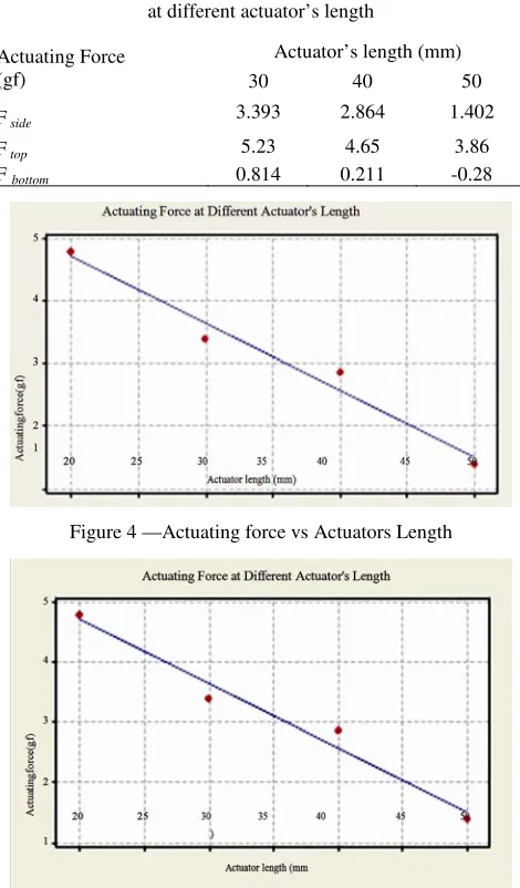
[image:3.612.67.292.103.549.2]In average, the recorded thickness of the fabricated IPMC filaments was 0.45 mm. Its average, the surface resistance was 13Ω, measured at two points of 5cm length. Relation between the actuating force over different IPMC actuator length was presented in a graph in Figure 4. Obviously the recorded generated force declined at constant as the length of the IPMC filament increased. The constant value is approximately 0.11 gf per mm of IPMC length. At 30 mm length, the bending tip force could reach up to near 5 gf. The recorded tip force at 50 mm length was 1.4 gf. In addition to this result, Table 1 shows the different actuating force at different position and actuating orientation for different length. The negative result from the bottom actuator was because of the load cell detecting in reverse motion. These data are the key reference in designing the cylindrical contractile thruster. Complex shape and fluid hydrodynamic requires the combination of IPMC actuator length and position for performance optimization.
Figure 2—Mechanics of Beam Model
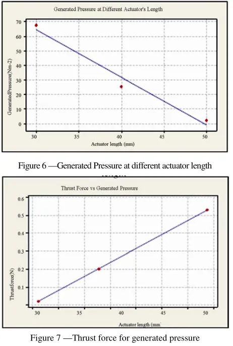
Figure 5 shows the oscillating speed at three different IPMC actuator lengths respectively. Oscillating speed increased in constant parallel to the increment of the actuator’s length. This phenomenon occurred because longer actuator would have wider bending angle and based on beam bending moment rules where longer actuator would have greater moment. Besides, longer actuator contains more water molecules that could increase the internal stress of the IPMC actuator. Figure 6 depicts the relationship between the generated jet pressure from the contracted balloon at different IPMC filament length. Exhibited pressure was exactly the increment of the internal constant air pressure level caused by IPMC filament actuation. At 3cm length, the recorded pressure was 0.0098 psi (67.57 Nm-2) and at 5 cm
length, the pressure was 0.0003 psi (2.07 Nm-2). This experiment was conducted as a preliminary reference for real application in water. In this case, the medium inside the balloon was natural air which has 1.1839 kg/m3 density at 25˚C. Though the density value of water and air is obviously differ, there is no issue as the density is only a constant value in the equation. However, there are several other factors that must be taken into account. These factors would be the balloon material, air compressibility and barometric pressure. In every actuating system, the major concern is to transfer the maximum applied force into the work with minimum waste.
During the radial contraction, the tip force was applied to reduce the balloon radius. Elasticity of the balloon material provides force resistance that could reduce the effect of the tip force. Low butadiene (which impart elasticity to the nitrile copolymer) Nitrile balloon was utilized rather than rubber to reduce the antagonist resistance. Air compressibility had bigger impact on the developed system. The entrapped air might have precise reading to the pressure transducer but less accuracy because of the air compressibility. Just like the resistance of the balloon material, the compressibility of the air absorbs the transferred energy from the IPMC actuation. In real application, the effect of energy absorption could be reduced because water has lower compressibility compared to air and the nozzle is open to jetting out the slug. The other consideration was the barometric pressure. Above the sea level, the IPMC actuators are oscillating easily compared to real underwater application. In submerge state, it might be better in contraction force due to depth level but it could be relatively difficult for the IPMC inflate the thruster during drawing in the water. Once the generated jet pressure had been acquired, the thrust force, Tf would be determined using Equation (7). By assuming that the jet was in cylindrical form, thrust force is the product of jet pressure and the jet cross sectional area. The cross sectional area for the jet was 0.00786 m2. Relation between the generated jet pressure and the resulting thrust force was exhibited in Figure 7.
Tf = Pj An … (7)
The result shows that the thrust force and jet pressure had linear positive relationship. As noticed in previous chapter, the generated jet Table 1—Characterization of the actuating force
at different actuator’s length
Actuator’s length (mm) Actuating Force
(gf) 30 40 50
F side 3.393 2.864 1.402
F top 5.23 4.65 3.86
[image:4.612.62.297.323.724.2]F bottom 0.814 0.211 -0.28
Figure 4 —Actuating force vs Actuators Length
pressure decreased if the actuator length increased. Therefore, shorter actuator provided better thrust force. Regression analysis using Minitab software shows that the P value of the variables is 0.004. The linear equation for this relation is:
Tf (N) = 0.00282 + 0.00779 Pj(Nm-2) … (8)
Conclusion
Generally, higher tip force actuation gives better radial contraction and thus the jet pressure. In this experiment, the generated pressure was relatively small, which was around 0.0098 psi for 3cm IPMC filament length. It varies due to the length of the IPMC actuator. The jet pressure value is vital to determine the thrust force generated by the contractile thruster system. Thus, this method provides fundamental guideline to measure the actual water jet
thrust force. In further studies, it is suggested to observe the effect of IPMC actuator slope and allocation degree rather than current orthogonal positions.
Acknowledgments
This project is funded by Ministry of Education (MOE) via its Fundamental Research Grant Scheme (FRGS). Authors are grateful to Universiti Sains Malaysia and Active Materials and Processing Laboratory (AMPL), University of Nevada for providing the facilities to conduct the research works.
References
1 Shaari, M.F., Samad, Z., Abu Bakar, M.E. and Jaafar, M, Design consideration of bio-inspired contractile water-jet thruster for mini autonomous underwater robot, Advanced Materials Research II, 463-464 (2012) 1583-1588
2 Abu Bakar, M.H., AUV propeller design through CFD and PVL, in International Conference on Underwater System Technology: Theory and Applications 2008 (USYS'08), Bali, 2008
3 Ye, X.F., Hu, Y.N., Guo, S. and Su, YD., Driving mechanism of a new jellyfish-like microrobot, Proc. Of 2008 IEEE Int. Conference on Mechatronics and Automation, Japan, 2008
4 Shahinpoor, M. and Kim, KJ., Ionic Polymer Metal Composite:I. Fundamentals, Smart Mater. Struct. 10 (2001) 819-833
5 Carpi, F. and De Rossi, D., Biomimetic dielectric elastomer actuators, The 1st IEEE/RAS-EMBS Int. Conf. on Biomedical Robotics and Biomechatronics BIOROB, Pisa, 2006
6 Wang, Y., Wang, Z. and Li, J., Initial design of a biomimetic cuttlefish robot actuated by SMA wires, 3rd Int. Conf. on Measuring Tech. and Mechatronics Automation, Shanghai, 2011 7 Shi L.W., Guo, S. and Asaka, K., A novel butterfly-inspired underwater microrobot with pectoral fins, Proc. Of the IEEE Int. Conf. of Mechatronics and Automation, Beijing, 2011 8 Yeom, S.W. and Oh, I.K., A biomimetic jellyfish robot based
on ionic polymer metal composite actuators, Smart Mater. Struct. 18 (2009)1-10
9 Ji,A.J., Park, H.C., Nguyen, Q.V., Lee, J.W. and Yoo, Y.T, Verification of Beam Models for Ionic Polymer-Metal Composite Actuator, Journal of Bionic Engineering, 6 (2009) 232–238
10 Desrochers, M.F., Olsen, G.W. and Hudson, M.K, A ground test rocket thrust measurement system, J. of Pyrotechnics, 14 (2001) 50-55
11 Krueger, P.S., Moslemi, A.A., Nichols, J.T., Bartol, I.K. and Stewart, W.J., Vortex rings, in bio-inspired and biological jet propulsion, Adv. in Sci. and Tech., 58 (2008) 237-246 12 Brasseur, J.G. and Dodds, W.J., Interpretation of intraluminal
[image:5.612.66.297.103.446.2]manometric measurements in terms of swalling mechanics, Dysphagia, 6 (1991) 100-119
Figure 6 —Generated Pressure at different actuator length