ISSN: 1992-8645 www.jatit.org E-ISSN: 1817-3195
AUTOMATIC SELECTION OF FILTERING DEVICES IN A
DISTRIBUTED INTRUSION PREVENSION SYSTEM
1
ELMEHDI BENDRISS, 2BOUBKER REGRAGUI
1
SI3M, ENSIAS 2
SI3M, ENSIAS
E-mail: [email protected] , [email protected]
ABSTRACT
We presented in a previous article [1] a distributed intrusion prevention system based on honeypots for collecting malicious data. Among important questions to handle there is the choice of filtering device on which a filtering rule has to be applied. In this paper we propose a solution which will allow automatic selection of filtering device in the distributed IPMS platform. These devices will be configured to block unauthorized traffic. This solution must ensure full integration with the IPMS architecture.
Keyword: Intrusion Prevention System (IPS), Distributed System, Network Sensors, Network Filtering
1. INTRODUCTION
Every networked device needs a perimeter level protection against unauthorized accesses. Even for standalone computers, major security
vendors give an all in one software integrating an
antivirus, a firewall and sometimes host based IDS/IPS. For small networks, the use of a linux based gateway with iptables[2] enabled and squidguard proxy[3] can be enough to have a good level of protection in both network and application levels.
In higher levels of network complexity multiple filtering devices are needed and a well-established framework must exist in the security team to choose on which device a rule must be implemented. When this action is automated, risk of implementing rules on wrong device can have dramatic consequences on business activities.
Through this work we propose a method that takes into consideration the structure of the network to select the device to implement a filtering rule in. The previous work [1] presented the distributed intrusion prevention system (IPMS) based on honeyd[4] for data gathering. The automatic selection of filtering device is very important for IPMS autonomy and reliability.
Deciding if which IP address will be blocked is not in the scope of this article. We will
assume that the IP to block was identified and we will name it IPb.
2. NETWORK STRUCTURE
Enterprises’ networks can be structured on different parts that have different security needs and that also have different impact on business when an incident happens. By incident we mean any “… act of violating an explicit or implied security policy” [5].
Most networks can be split into following blocs:
• Demilitarized Zone (DMZ): the DMZ
contains servers hosting services for public purpose and that are reachable from Internet. For example, the email server of the company, the web server and so on. These servers will never initiate a connection to the inside of the company network.
• Frontend Network (FE): in a
backend/frontend structured network,
ISSN: 1992-8645 www.jatit.org E-ISSN: 1817-3195
• Backend Network (BE): these servers are
not reachable from external networks. The security policy may deny direct access even for internal company users to this network without going through FE network. This network can host all servers having/providing access to company data (mailboxes, directories, databases…etc.)
• Users networks (userLan): a network
through which internal users connect to company network and resources. This can be structured into VLANs [6] with different access levels to resources. If such levels are used, it will be necessary to consider every VLAN as a userLan by itself. In the sake of keeping this article simple, we will consider that we have only one userLan
• Data Network (dataLan): this network is in
general accessible only through BE servers. Some storage technologies use IP for transport (like iSCSI [7] and NAS storage [8]) that’s why it is important to have this network in mind when setting up network security.
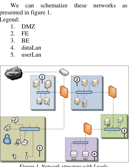
We can schematize these networks as presented in figure 1.
Legend:
1. DMZ
2. FE
3. BE
4. dataLan
[image:2.612.91.303.392.665.2]5. userLan
Figure 1. Network structure with Levels
In this example, we have three firewalls and one router which also can have access-list capabilities for filtering traffic. We will not consider this case and we will only focus on firewalls.
3. LEVELS, CRITICALITY, COMMUNITY
AND SID.
In order to implement our selection algorithm we introduce four notions. Each one will impact the final decision.
3.1 Levels
Before talking about levels, let’s just remind the reader that this algorithm is linked to the IPMS architecture. In IPMS we said that honeyd based sensors will be put in different places in the network. So the level will reflect the placement of each sensor in the network. As a consequence, when a sensor sends collected data to the analysis engine, we will have an exact idea about the network that the attack has reached. So levels will be: DMZ, FE, BE, DataLan and userLan as defined previously.
Obviously, an attack which reached the BE network is more critical than an attack which was detected in the DMZ or FE networks. Thus, we associate a weight to every level as follows:
1. DMZ : 10
2. FE : 20
3. BE : 40
4. dataLan : 80
5. userLan : 100
These values can be changed by the IPMS administrator to reflect the real impact of a security breach on business. Of course, if we have multiple VLANs in userLan level (for example, a vlan for normal users and a VLAN for IT admins) the administrator must set the weight by VLAN.
3.2 Criticality
The IPMS is mainly based on honeyd sensors to collect data and trigger other actions. But at the same time, the IPMS can use data from other network devices like intrusion detection systems (IDS) or any device which is IDMEF/IDXP [9, 10] capable. So we can introduce the notion of certainty: an IDS is more certain than a honeyd sensor when it reports an attack because it is based on attacks’ signatures so the probability of false positive is nearly inexistent.
ISSN: 1992-8645 www.jatit.org E-ISSN: 1817-3195
3.3 Community
The IPMS is a distributed and collaborative prevention system. The principle of Community is introduced to make a filtering decision spread beyond the enterprise network to other subsidiaries or other companies with the same security needs (like partners for example). If a community is set all networks sharing the same community must share the same levels and criticality, or at least be homogeneous in term of network structure.
3.4 SID, Sensor Identifier
The three notions previously introduced let us define the SID of a sensor by the expression:
SID := <level> . <ID> . < Criticality | default := 1>
. [Community | default := 0]
• <level> : mandatory field, contains the
level of the sensor
• <ID> : mandatory field, contains the
unique identifier of the sensor. This identifier is automatically generated by the IPMS when a new sensor is added
• < Criticality | default := 1> : mandatory
field, contains the criticality factor, if not specified by the IPMS administrator the default value is 1 (neutral)
• [Community | default := 0] : optional
field, contains the community id, if not specified by the administrator the default value is 0.
For example, the sensor with ID 15, in the frontend network with no criticality factor will have the SID : 20.15.1.0
4. FILTERING DEVICE SELECTION
ALGORITHM.
After having defined level, criticality, community and SID notions we present the algorithm to select on which filtering device, known as filtering subsystem in the IPMS architecture, will be concerned by a decision of
blocking a specified IP address, or IPb as noted in
the introduction.
4.1 The algorithm
/***** Step 1 : variables definition *****/
Array Tab_levels [] ; /* this array is generated
based on levels defined by the administrator in the
IPMS configuration.*/
Array Tab_SID[] ; /* temporary array to
hold SIDs */
Array Tab_Devs[] ; /* temporary array to
hold IP addresses of determined filtering devices by
the algorithm */
Array Tab_Nets[] ; /* temporary array to
hold networks’ addresses determined by the
algorithm */
Struct A_BLOQUER{
String IP_SOURCE ;
String IP_DESTINATION ;
String PORT_SOURCE ;
String PORT_SOURCE ;
} /* A structure to hold information used for
filter definition. Elements of the structure are given
as indication */
Struct A_BLOQUER a_bloquer ; /*
definition of a variable based on previously defined
structure */
/***** Step 2: functions prototypes *****/
level get_level (SID) ; /* this function returns
the level associated to an SID */
SID[] get_SID_by_level (level) ; /* this
function returns an array of SIDs of a given level
*/
string get_net_from_ip(SID) ; /* this function
returns the IP address of a given sensor / SID */
string[] get_filtering_device_by_net (string) ; /*
this function returns an array of IP addresses
associated to a filtering device in a given IP subnet
*/
Boolean apply_filter (IP=b, A_BLOQUER) /* this
function applies a filtering rule. Rules are in a
variable of type A_BLOQUER and are applied to
filtering device with the IP address given as
ISSN: 1992-8645 www.jatit.org E-ISSN: 1817-3195
/***** Step 2: Algorithm *****/
If (IS_ATTACK == TRUE) then
/* we get the level of the sensor who captured the
suspected traffic */
l ← get_level (SID) ;
/* we get SIDs of all sensors having a level lower
than or equal to the one who captured the
suspected traffic */
for (int i=0 ; i<sizeof(Tab_Levels) ; i++) {
if ( (li←Tab_Levels[i]) > l) then
exit for loop
end if
Tab_SID[] ← get_sid_by_level(li) ; // push
}
/* getting IP networks’ addresses of sensors with
SIDs determined in the previous for loop */
i ← 0;
while ( i < sizeof(Tab_SID) ) do
Tab_Nets[] ← get_net_from_ip(i) ; // push
End while
/* finally, we get IP addresses of filtering devices in
the networks determined in the previous while loop
*/
i ← 0;
while ( i < taille(Tab_Nets) ) do
IP_Devs[] ← get_filtering_device_in_net(i) ;
// push
End while
/* we apply filtering rules on each filtering device*/
i ← 0;
while( i < taille(Tab_Devs) ) do
if ( Apply_filter(Tab_Devs[i], a_bloquer) )
then
Actions to do after the filtering rule has been
successfully applied to a device.
else
Actions to do in case of failure while
applying filtering rules to a device.
End if
End while
End if
4.2 Execution of the algorithm
The algorithm starts by determining the level of the sensor that captured the suspected data and led to a decision of blocking the source IP address. The idea behind this step is to:
• Have a clear idea of how many sensors
were in the path of this attack and network data was not suspected, which may indicate a problem in decision scheme
• Have all IP networks that belongs to the
same level (or a lower one) than the current sensor as we may have different IP addresses for the same level (think about userLan with multiple VLANs)
Once this is done, we can have all IP addresses of filtering devices in the networks we determined in the first step of the execution. This will allow us to filter network traffic in all these devices without missing any one either in the network with the sensor or in remote networks.
The community was not introduced in the present algorithm as it is just for demonstration.
4.3 Tests and results
As in our previous article [1], filtering devices were based on Linux boxes with iptables. RSH (Remote SHell) was used to remotely apply new chains to the filtering device. To simulate a large network of filtering devices virtual machines were used on multiple hosts and with multiple virtual networks.
We also presented (in [1]) the algorithm used to fire the filtering action by using the function
“ConfigureDevice(Rule)”. We can alter this
ISSN: 1992-8645 www.jatit.org E-ISSN: 1817-3195 The algorithm executed as expected and
filtering rules were dispatched as expected. The execution showed also that some rules do not need to be implemented on some filtering devices systematically. For example, if an IP is blocked in the very most peripheral filtering device what will be the need to reapply the same rule on all internal ones? And finally, for userLan level, maybe filtering by IP will not be efficient as in the case of using DHCP for example, the user could change its IP address and retry with his attack. Of course, we can go with DHCP reservations but integrating a lower level filtering (MAC address) for userLan may be necessary. We can update the algorithm with a check of the filtering to apply depending on the level of the sensor. For our case, our primary target is Internet attacks and IP filtering, so we don’t go further in this path for the moment.
5. CONCLUSION.
In this article we tried to improve the IPMS platform [1] by automating the selection of filtering device on which a filtering rule has to be applied. Nevertheless, and as discussed in the results, we can improve this algorithm to adapt further to real word cases.
The notion of community adds a level of complexity to the platform as it adds the need of securing communication with external networks. When sharing a filtering rule over internet this communication should be secured.
From another hand, an organization would not share all private network configuration with its partners, so a way to distribute the algorithm using agent based calculation, meaning having an agent in every network instead of a centralized method.
Having all information about network configuration, even encrypted, in one place make it a good target for attacks above all when information for remote access is also stored in the same location. So special care should be taken for securing this platform’s servers
REFERENCES
[1] E.Bendriss, B. Regragui, “Honeypot based intrusion management system: from a passive architecture to an IPS system”, JATIT, pp 792-797, Vol. 47.No. 2, 2013
[2] Wikipedia, Iptables, online, http://goo.gl/AFhni, last visited: April,
4th, 2013.
[3] SquidGuard, online, http://squidguard.org/, last visited: April, 4th, 2013.
[4] N. Provos, T. Holz. « Virtual Honeypots », Addison Wesley, 2008, ISBN: 0-321-33632-1 [5] US-CERT, Incident Definition, on
line, http://goo.gl/dTQFU, last visited: April, 4th, 2013.
[6] Wikipedia, VLAN, online, http://goo.gl/ueKhc, last visited: April,
4th, 2013.
[7] Wikipedia, iSCSI, online, http://goo.gl/6MVuo, last visited:
April, 4th, 2013.
[8] Wikipedia, NAS, online, http://goo.gl/MnJ1v, last visited: April, 4th, 2013.
[9] IDMEF, RFC, online, http://goo.gl/G8rfx, last visited: April, 4th, 2013.