A MICROCONTROLLER-BASED AUTOMATIC HEART
RATE COUNTING SYSTEM FROM FINGERTIP
1MAMUN, A. L., 2AHMED, N., 3ALQAHTANI, M., 3ALTWIJRI, O., 2
RAHMAN, M., 4,*AHAMED,
N.U., 5RAHMAN, S.A.M.M., 2AHMAD, R.B., 4SUNDARAJ, K.
1
Electronics Division, Atomic Energy Centre, Dhaka-1000, Bangladesh
2
School of Computer and Communication Engineering, Universiti Malaysia Perlis, Malaysia
3
Biomedical Technology Department, College of Applied Medical Sciences, King Saud University, Kingdom of Saudi Arabia
4
AI-Rehab Research Group, Universiti Malaysia Perlis, Kampus Pauh Putra, Arau-02600, Perlis, Malaysia
5
College of Computer Science and Information System, Najran Univeristy, Kingdom of Saudi Arabia Email:4,*[email protected]
ABSTRACT
This article describes the design process of a low cost and portable microcontroller based heart-rate counting system for monitoring heart condition that can be implemented with off-the-shelf components. The raw heart-rate signals were collected from finger using IR TX-RX (Infrared Transmitter and Receiver pair) module which was amplified in order to convert them to an observable scale. The inherent noise signal was then eliminated using a low pass filter. These signals were counted by a microcontroller module (ATmega8L) and displayed on the LCD panel. An algorithm has been developed which was programmed into the microcontroller to run the proposed heart rate counting system. The results obtained using the developed device when compared to those obtained from the manual test involving counting of heart rate was found satisfactory. The proposed system is applicable for family, hospital, clinic, community medical treatment, sports healthcare and other medical purposes. Also, fit for the adults and the pediatrics. However, presented method in the developed system needs further investigation and need more functionality, which may be useful to consider advance in future research.
Keywords: Heart Rate, Microcontroller, Finger-Trip, Sensor.
1. INTRODUCTION
Currently there is a growing research interest in measuring the heart rate from the body, because it is one of the important parameters of the human cardiovascular system [1]. This countable rates from the heart is the number of heartbeats per unit of time which is typically expressed as beats per minute (bpm)[2]. The rate of the bpm varied on subject-to-subject, like age, physical condition and activities. For example, the average heart rate of a healthy adult at rest is around 72 bpm [3]. On the other hand, infants and babies have a much higher heart rate than older individuals which is above 120 bpm [4].
However, to understand and to count the exact bpm from different subjects, it is necessary to develop an easy to use, portable and low cost heart rate monitoring system. Because, the measurement of heart rate is used by medical professionals to assist in the diagnosis and tracking of medical conditions. It is also used by individuals, such as athletes (during prolonged exercise), who are interested to view their heart rate to acquire maximum efficiency [5]. There are many ways to
Many researchers have developed and designed the heart rate counting system using microcontroller and finger trip. For example, Ahmed et al. designed a microcontroller (PIC17C44) development board and developed a real-time algorithm for monitoring the heart rate for long-term [10]. Ahamed et al. developed a system for muscle function monitoring using PIC18F4455 microcontroller [16]. Then Jayasree et al. designed and developed a simple hardware setup for sensing blood volume pulse using a PIC microcontroller based for measuring the heart rate [11]. Some other researchers also developed microcontroller based heart rate counting system from fingertip sensor [12-15].
In our development process we used the sensor unit which consists of an infrared (IR) light-emitting-diode (LED) and a photodiode. The IR diode transmits an infrared light into the fingertip (placed over the sensor unit), and the photodiode senses the portion of the light that is reflected back. The intensity of reflected light depends upon the blood volume inside the fingertip. So, each heart beat slightly alters the amount of reflected infrared light that can be detected by the photodiode. The magnitude of the pulses at the output of the photo diode is too small to be sensed directly by a microcontroller. Therefore, a two-stage high gain, active low pass filter is designed using Operational Amplifiers (Op-Amps) to filter and amplify the signal to appropriate voltage level so that the pulses can be counted by a microcontroller to determine the heart rate and displayed in LCD.
2. MATERIAL AND METHODS
2.1 Hardware System
The design of the hardware is based on an embedded system implementation using the ATmega8 microcontroller from ATMEL, USA. The block diagram of the hardware system is shown in Figure 1. The hardware system includes, IR transmitter that transmits (TX) the code to the IR receiver (RX) in the machine over a local IR link (amplifier and low-pass filter). A microcontroller (MCU) had been chosen in the hardware platform. Then MCU Control the Visual Display by the LCD.
Figure 1 Here
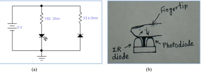
2.2 IR Sensor
The sensor consists of an IR light emitting diode transmitter and an IR photo detector acting as the receiver. The IR light passes through the tissues. Variations in the volume of blood within the finger modulate the amount of light incident on the IR detector. In this design, both the IR transmitter and
receiver placed on the same plane and the finger functioned as a reflector of the incident light. The IR receiver monitors the reflected signal. Here, an infrared LED (OPB100EZ) and phototransistor (OPB100SZ) is used as sensor device. Figure 2(a) presents the circuit design of the sensor and Figure 2(b) shows how the sensor working using fingertip.
Figure 2 Here
2.3 Amplifier and Filter Design
Filtering process is required to remove the undesirable noises. The weak nature of the IR signal and the noise affecting on it, requires the implementation of a range of filters and differential amplifiers. The signal conditioning circuit consists of two identical active low pass filters with a cut-off frequency of about 2.5 Hz. Cut Off Frequency =1/2πRfCf = 1/2×3.1416×68K×1uF=2.34 Hz; where, Rf=R1=R4=68KΩ and Cf=C1 =C3=1µf.
This indicates that the maximum measurable heart rate is about 150 bpm. The gain of each filter stage is set to 11, giving the total amplification of about 121. Gain of each stage=1+Rt/Ri =1 + 680KΩ/ 68KΩ=11; where, Rt=R2=R5=680KΩ and Ri=R3=R6=68KΩ. A 1 uF capacitor at the input of each stage is used to block the dc component in the signal. The equations for calculating gain and cut-off frequency of the active low pass filter are shown in the circuit diagram in Figure 3. The two stage amplifier/filter provides sufficient gain to boost the weak signal which is 3-4 mV and coming from the IR sensor unit, and convert it into a pulse. This pulse is counted by microcontroller. Then an LED is used which blinks each time when the heart beat is detected.
Figure 3 Here
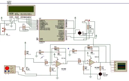
2.4 The Microcontroller Block
display. Figure 4 shows the microcontroller block of the system.
Figure 4 Here
2.5 PCB Design and Fabrication
PCB (printed circuit board) circuit design has proposed (Figure 5 (a) and Figure 5 (b)) for attaching hardware devices in the system. The PCB was design by using Proteus 7.7 Professional software (ISIS 7 professional).
Figure 5 Here
2.6 Software Design
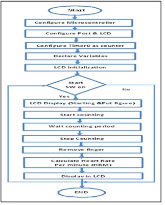
Software design includes developing algorithm for the system, allocating memory blocks, writing the separate routines for different interfacing devices and testing them on the designed hardware. Interfacing of the microcontroller with ADC, LCD and Sensor has been carried out using the software modules. The control program is written in basic programming language and compiled by BASCOM-AVR software (it is the Windows BASIC Compiler designed for Atmel's microprocessors). ISIS Proteus7.7 can combine with BASCOM AVR software in order that it can be used also to evaluate programs created using BASCOM AVR. A flowchart of the proposed software is shown in Figure 6.
Figure 6 Here
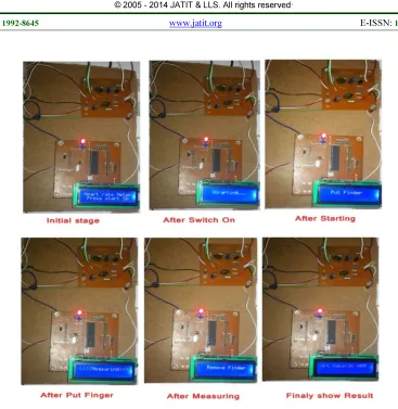
2.7 System Operation
Figure 7 demonstrates how the system is working as real time. Total six steps were performed to obtain the desired results
.
Figure 7 Here
3. RESULTS AND DISCUSSIONS
Analogue signals of heart rate acquired by the sensor through finger and input to PD-4 port of the microcontroller. The system was used to measure the heartbeat rate of a number of male and female volunteers. The results of the developed system compared with a conventional measuring method. These results show acceptable range compare to manual measurement. Another experiment was conducted where we measured the beat rate of two male volunteers at rest. The volunteers then performed some exercise (jogging)
for five minutes and their heartbeat rate was subsequently measured. The readings of the device were compared against the manual measurement. The manual measuring data were taken by counting the pulse from the wrist. Overall, the results are in an acceptable agreement with the actual readings. Table 1 shows the ten subject’s heart rate with the both ways. Another experiment was done with two subjects (presented in Table 2) where one female and one male was participated
Table 1 Here Table 2 Here
Finally, the main parameters (specifications) of the developed system are as follows:
• The system is compact, portable and user
friendly,
• Can detect the signal (hear rate) in real-time, • Low power consumption facility,
• The measuring range of the heart rates is within
30-bpm to 300 bpm,
• Recorded data can be transferred to a PC, • Display unit: 2.4" LCD,
• Internally powered equipment,
• Dimensions: 160 mm (L) x 135 mm (W) x 132
mm (H), weight: 200 g,
• The device has plug-in board and stand-alone
product,
• The product is applicable for family, hospital,
private clinic, community medical treatment, sports healthcare and other medical purposes. Also, fit for adult and pediatrics.
Our current prototype has some significant limitations, since there is no a built-in design or architectural limitation. But, creating the activation function is a challenge because of the limitations of the attached microcontroller. But, these limitations do not affect the developed system in real life.
4. CONCLUSION
expected with the upgraded module to improve and simplify the system for the users.
REFERENCES
[1] D. Ibrahim and K. Buruncuk, "Heart Rate Measurement from the Finger Using a Low-Cost Microcontroller," Near East University, Faculty Of Engineering, TRN, 2005.
[2] V. K. Yeragani, et al., "Heart rate and QT interval variability: abnormal alpha-2 adrenergic function in patients with panic disorder," Psychiatry research, vol. 121, pp. 185-196, 2003.
[3] J. M. Dekker, et al., "Low heart rate variability in a 2-minute rhythm strip predicts risk of coronary heart disease and mortality from several causes The ARIC Study," Circulation, vol. 102, pp. 1239-1244, 2000.
[4] R. H. Durant, et al., "Reliability and variability of heart rate monitoring in 3-, 4-, or 5-yr-old children," Medicine and science in sports and exercise, vol. 24, p. 265, 1992.
[5] M. Lester, et al., "The effect of age and athletic training on the maximal heart rate during muscular exercise," American heart journal, vol. 76, pp. 370-376, 1968.
[6] R. Kojima and Y. Nosé, "Rhythmical fluctuation of arterial pressure after implantation of cardiac prosthesis," Artificial organs, vol. 18, pp. 621-626, 1994.
[7] P. Galen, et al., "Systems And Methods For Detecting And Monitoring Arrhythmias Using the PPG," ed: US Patent 20,120,310,100, 2012. [8] G. Parati, et al., "Spectral Analysis of Blood Pressure and Heart Rate Variability in Evaluating Cardiovascular Regulation A Critical Appraisal," Hypertension, vol. 25, pp. 1276-1286, 1995.
[9] S. Kara, et al., "Low-cost compact ECG with graphic LCD and phonocardiogram system design," Journal of Medical Systems, vol. 30, pp. 205-209, 2006.
[10] F. Ahmed, et al., "A portable recorder for long-term fetal heart rate monitoring," Microprocessors and Microsystems, vol. 26, pp. 325-330, 2002.
[11] V. Jayasree, et al., "Design and Development Of a Simple Hardware Setup for Sensing
Blood Volume Pulse and a PIC
Microcontroller Based Heart Rate Meter," in Biomedical and Pharmaceutical Engineering, 2006. ICBPE 2006. International Conference on, 2006, pp. 256-258.
[12] H. Chatterjee, et al., "A microcontroller based system for real-time heart rate estimation from ECG signal," in India Conference (INDICON), 2012 Annual IEEE, 2012, pp. 1020-1025. [13] J. Prasath, "Wireless monitoring of Heart Rate
using Microcontroller," International Journal of Advanced Research in Computer Science and Electronics Engineering (IJARCSEE), vol. 2, pp. pp: 214-219, 2013.
[14] S. F Babiker, et al., "Microcontroller Based Heart Rate Monitor using Fingertip Sensors," Khartoum University Engineering Journal, vol. 1, 2011.
[15] Y.-C. Wei, et al., "Design of a microcontroller-based real-time heart rate variability measurement system using a low-complexity R-peak detection algorithm," Instrumentation Science & Technology, vol. 41, pp. 274-289, 2013.
Figure 1: Block Diagram Of Heart Rate Counting System
(a) (b)
[image:5.595.95.494.417.561.2]Figure 3: Schematic Of Filter And Amplifier Designed On Proteus 7.7 Electronic Design Suite
[image:6.595.92.535.433.713.2][image:7.595.92.513.81.302.2]
(a) (b)
Figure 5: Top And Bottom Surface Of The PCB Layout (A) Microcontroller Unit (B) Sensor Unit
[image:7.595.139.462.329.728.2]Figure 7: Developed System In Working Environment
Table 1. Results Of Measurement Of 10 People Heart Rate Per Minute
Subject Gender Age Heart beat by developed system
Heart beat by Manually
Error %
Subject 1 Male 22 85 84 1.04%
Subject 2 Male 22 84 82 2.38%
Subject 3 Male 20 78 78 0%
Subject 4 Male 22 90 87 3.33%
Subject 5 Male 32 100 102 2%
Subject 6 Female 22 76 77 1.32%
Subject 7 Female 40 104 103 0.96%
Subject 8 Female 20 68 66 1.47%
Subject 9 Female 22 72 71 1.38%
Subject 10 Female 22 84 85 1.19%
Table 2. Measurements Of Heartbeat Rate Before And After Exercise Using The Developed Device Together Wrist Measurements.
Subjects Gender Ag e
Condition Heart beat by developed system
Heart beat by Manually
Subject 1 Male 24 Before exercise 64 65
After exercise 90 88
Subject 2 Female 15 Before exercise 90 88