6
II
February 2018
E-Textile Military Jacket
Dinesh. N.S1, Bakiyalakshmi. V2, Jayachithra.R3, Dr. T. Kalavathi Devi
1, 2, 3, 4
B.E Student Dept. E&I Engg Kongu Engg College, Tamilnadu
Abstract: The focus of this paper is on the development of textile-based wearable electronics that can be integrated into military protective clothing. The manufacturing survey was conducted to determine the best performing and most durable materials to withstand the rigors of textile manufacturing and potential military use. Narrow woven technology was selected as one of the most promising textile manufacturing methods. In the battle field if our soldier gun down by enemy it will sense by piezoelectric sensor then automatically SMS sends to our army office. By this idea we easily found the soldier status in battle area. If soldiers strength is not enough against enemy’s strength then we sends extra force to the battle area. It is very easy to save our country. Keywords:global positioning system (GPS), local area network (LAN), EDR (Enhanced Data Rate), AFH (Adaptive Frequency Hopping Feature), SPP (Serial Port Protocol).
I. INTRODUCTION
In battlefield our army soldiers facing lot of problems because of the enemies. Sometimes they attack our soldiers without any intimation in border. Main aim of this paper is to intimate illegal attack or sudden attack to the base station using piezoelectric crystal, microcontroller and GSM. We keep the piezoelectric crystal over the jacket it is used to sense the vibration. Whenever our soldiers are in duty for watching in border if anybody attacks, the piezoelectric sensor get vibrates so it produce some voltage, it sense by the microcontroller. Then the microcontroller signals the base station by using GSM.
II. LITERATURE SURVEY
This chapter deals with the operation of existing methods and their limitations. From the literature survey, the integration of sensors and actuators can increase the functionality of military uniform. However, this may lead to decrease in the real protection for soldiers from weapons and other related threats. The integration of sensors and actuators into the uniforms should not compromise a soldier’s capabilities in terms of mobility, survivability and sustainability.
A. Modern Helmet Systems
In today's modern helmet systems, the soldiers can get up-to-the-minute information via a helmet- mounted Global Positioning System (GPS), wireless voice and data communication system, and a wearable computer linked to an wireless Local Area Network (LAN). A flip-down display on the helmet allows the soldier to scan the surroundings in the darkness, using thermal and night-vision sensors connected to his weapon. This display also gives each soldier a view of a situation map that can pinpoint where both the friends and the foe are located, in real- time. With that knowledge, the soldier can better figure out how to tackle the enemy. Modern Helmet is shown in the fig.1.
Modern helmet communicates the base station or other soldiers manually when send the information throughout the mail. If any accidents or attacks happen to the soldiers, possibly they cannot pass it manually.
III. METHODOLOGY
Electronic textiles, or simply e-textiles, are textiles with embedded electronics and some fiber materials possessing electrical characteristics and providing some useful functions. The various functionalities where electronic textiles are making inroads include communication (both wired and wireless), enhanced mobility, survivability. Developments in sensors and wireless technology enable improvement in the performance of personal combat equipment. Some of the recent functionalities achieved by integration of e-textiles include physiological status monitoring, wearable power supplies, and sensing of environmental conditions as well as the detection of chemical and biological threats. The fig.2 shows the Block diagram of E-Textile military jacket and it illustrates how each and every component is interfaced to do respective function.
Fig.2 Block Diagram of E-Textile Jacket
The regulated power supply acts as a source for all the components involved in this project. Piezoelectric crystal used here plays the role of sensor which senses the vibration produced in the battlefield and develops an equivalent voltage. Microcontroller PIC 16F877A functions as a mediator between sensor and output devices. LCD is used to display the commands which are passed by the microcontroller.
IV. INTERFACING CIRCUITS
When a bullet hits the person, the body experiences vibration and this vibration is transferred as a force to piezo electric crystal. Unit cell is symmetrical in most of the crystals whereas in the piezo electric crystal it is not. Normally they are electrically neutral. i.e. the atoms present inside the piezo electric crystal may not be arranged.
Fig.3 Overall Circuit Diagram of Military Jacket
Symmetrically, but their electrical charges are perfectly balanced. Both positive and negative charges are present in equal amount inside the piezo electric crystal. So that a positive charge in one place cancels out a negative charge nearby. Hence the force exerted on the piezo electric crystal tends it to deform thereby unbalancing the positive and negative charge present inside the crystal and causing net electrical charge to flow. (i.e.).a voltage is produced across its opposite faces. The voltage signal produced by the piezo electric crystal is given as the signal to the microcontroller. The microcontroller compares the signal fed to it by the piezo electric crystal with the set point value (pre defined value given to the microcontroller).
V. SIGNAL CONDITIONING CIRCUITS
A. Power supply circuit
A 6V DC (Direct Current) source is used in this circuit, but microcontroller and other electronic devices work only in 5V. It may
leads to damage the overall circuit due to over voltage. Voltage sources in a circuit may have fluctuations resulting in not giving
Fig.4 Connection Diagram of Power Supply
Table 1: 7805 Pin Functions
B. Design Of Amplification Circuit
A piezoelectric sensor is a device that uses the piezoelectric effect, to measure changes
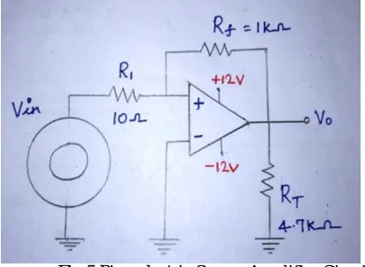
in pressure, acceleration, temperature, strain, or force by converting them to an electrical charge. Normally they are electrically neutral. i.e. the atoms present inside the piezo electric crystal may not be arranged when it is in normal condition. Vibration (force) is applied on the piezoelectric crystal; it produces voltage due to unsymmetrical arrangement of positive and negative ions. Fig.5 shows the piezoelectric sensor amplifier circuit. For example, Design amplification circuit with gain of 100, because piezoelectric
sensor produces mill volt (mV) output.
Assume the feedback resistance to be 1KΩ and input resistance to be 10Ω,
R1=10 Ω
RF=R2=1KΩ
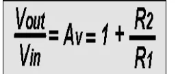
Since amplifier is used in a non-inverting configuration, gain of the amplifier is Gain A = 1+ (Rf/R1) =1+ (1000/10)
PIN No.
PIN
DETAILS DESCRIPTION
1 INPUT Input voltage (7V-35V)
In this pin of the IC positive unregulated voltage is given in
regulation.
2 GROUND Ground (0V)
In this pin where the ground is given. This pin is
neutral for equally the input and output.
3 OUTPUT Regulated output; 5V (4.8V-5.2V)
Therefore, A = 101
Fig.5 Piezoelectric Sensor Amplifier Circuit
[image:6.612.226.385.337.487.2]From the piezoelectric sensor amplifier circuit, output voltage is analyzed with respect to the input applied in the crystal. Table 2 shows the piezoelectric sensor analysis.
Table 2 Piezoelectric sensor Analysis
C. Overcome Method
When piezoelectric crystal produces maximum voltage due to applied force, it causes damage to the microcontroller and other devices which are connected to the system. So, the inverse rule method is followed here. The voltage obtained from the crystal is subtracted from 550mV which is the maximum voltage and the subtracted value is multiplied by a multiplication factor of 10. Threshold voltage of sensor = 116Mv
Maximum voltage of sensor = 550mV
Output voltage = maximum voltage – input voltage
PIEZOELECTRIC STATUS
OUTPUT VOLTAGE
Crystal Voltage 100-140mV
Stable Condition 9-10 V
Minimum
Vibration 18-20 V
Maximum
With the help of inverse method, relationship between applied force and voltage from crystal as non-linear characteristics is shown in the fig.6. It helps the microcontroller protect from piezoelectric output voltage.
VI. RESULTS AND DISCUSSION
Thus the E-textile military jacket has been designed to intimate the enemies’ unlawful (illegal) attack in the border area. When the attack happens in battlefield, microcontroller transfers the message to other soldiers in the predefined path that is already programmed and fed into the microcontroller.
Fig.7 Under Normal Condition
When there is no excitation, LCD displays the message as “E-TEXTILE MILITARY JACKET” as shown in the figure 5.1. If some abnormal condition occurs then the bluetooth receives the command from the microcontroller and it is displayed as “INJURY OCCURRED” as shown in the figure 5.2. Figure 5.3 shows the bluetooth output.
Fig.9 Bluetooth Output
VII. CONCLUSION
This jacket rescues soldiers from enemies. The main aim is to increase the protection and survivability of the combat soldiers. The goal is to help soldiers to do everything they need to do with smaller equipment and a lighter load. If electronics and piezoelectric technologies could be integrated successfully into the textiles, there could be a striking improvement in the battlefield communications.
A. Future Scope
The Nano materials and smart structures can also provide the future soldiers with super strength, protection against bio- weapons, and even a way to communicate covertly. The future warrior systems include global positioning systems, combat identification sensors, monitors, chemical detectors, and electronically- controlled weapons, for over protecting our soldiers.
REFERENCES
[1] Sahin.O, Kayacan.O and YazganBulgun.O (2015) ‘Smart Textiles for Soldier of the Future’- Defence Science Journal, Vol. 55, pp. 195-205. [2] SaddamhusenJamadar ‘Applications of Smart and Interactive Textiles. Textile learner’
[3] Winterhalter C and Teverovsky J. (2004) ‘Development of electronic textiles for U.S.military protective clothing systems’
[4] R.Nayak, L.Wang andR.Padhye ‘Electronic textiles for military personnel’ School of fashion and textiles, RMIT University, Australia. [5] Windmiler.J.R, Wang.J (2013) “Wearable Electrochemical sensor and Biosensors. A Review’.
[6] MatteoStoppa and Alessandro Chiolerio (2014) ‘Wearable Electronics and Smart Textiles’ – Journal of Sensors, pp.58 [7] Unsal.M, Niezrecki.C and Crane.C ‘Two semi active approaches for Vibration Isolation’ University of Florida, pp. 1-6. [8] Tilak Dias (2015) ‘Electronic Textiles’ first edition, Smart fabrics and wearable technology, Vol.2, pp.73-131. [9] Dr.MerihSarıışık (2016) ‘International Journal of Clothing Science and Technology’, Vol. 28, pp. 108-128.