PROGRAMMING
MANUAL
LI N K DIVISION
@)@~~~~&[S~~~©O@O@~ INC.
SIMULATION & CONTROL GROUP
I
I
I
I
I
I
I
I
I
I
I
I
I
I
I
.1
I
.1
J
...
LP1570-5 30 JULY 1964 24-7-64
Printed in UqSoA~
---- ---===~~~=====-~-==-~
MARK I
PROGRAM MANUAL
TWA
Prepared by
Link Group
General Precision, Inc.
---~-
----I
I
I
I
I
I
I
I
I
I
a
I
I
I
I
I
I
I
I
.'
I
I
I
I
I
'I
I
I
I
I
I
I
I
,I
I
I
I
I
I
Section I II MARK ITABLE OF CONTENTS
COMPUTER CHARACTERISTICS
1-1 G e n e r a l . . .
1-7 Main Arithmetic Unit . .
1-8 General...
1-9 Organization:..
1-13 24-Bit Arithmetic Accumulator
1-17 24-Bit Salvage Register.
1-19 Magnetic Drum . . . .
1-20 General...
1-31 Core Memory. . . • . . . . • .
1-32 General 0 • • • • • • • • •
1-36 Priority. . . . . • . .
·
. .
1=38 Boolean Storage . . . • .
·
.
1-43 Analog to Digital Converter
1-44 General.. 0 • 0 •
1-45 Scaling.. 0 • • • • • • • • • •
1-46 Priority... 0 • • •
·
. .
·
.
1-48 Digital to Analog Output System
1-49 General... . . . .
1-55 Boolean Arithmetic Unit 0 0 0 0 • • • • • • • •
1-56 General... 0 • 0 • 0 0
·
.
1=57 Salvage Register . . 0 • • 0 0 0 •
1-60 Digital Linear Function Interpolator 0
1=61 G e n e r a l . . . • •
·
.
.
1-64 Scaling 0 • 0 p • • • •
·
.
1-65 Flow of Information. . 0
" 0 " • •
1-70 Timing. 0 0 0 • • • • 0 o • 0 e 0
·
.
1-73 Two Variable Function 0 • • • • • • • • • •
1-79 Radio Aids Data Preselector •
1-80 G e n e r a l . . .
1-86 Frequency Inspection. .
1-90 Geographic Position Inspection.
1-93 Preselection..',..
1-96 Keying Fu'nction Gener'ator .
1-97 G e n e r a l . . .
1-98 Priority.... j 0 •
LIST OF INSTRUCTIONS
2-1 General 0 • 0 0 ~
2-6 Instructions 0 0 • • • • • • • •
2-8 Load Accumulator ,
. .
2-9 Store Accumulator .
• CI .. 0
· .
.
~=-~---Section
III
MARK I
TABLE OF CONTENTS (Cont)
2-10 .. No-Operation . . . . 0 0 • 0 • • •
2 -11 Add. 0 • 0 • • • • • 0 • • • • • • • • • •
2-12 Subtract 0 0 • • • • • • • • • • • • • • • •
2-13 M u l t i p l y . . .
2-14 Negative Multiplication . . . . • . . . .
2-15 Square. 0 0 0 0 o· • • 0 • 0 ct • • 0 • 0 0 •
·2 -16 D i v i d e . . . • . . . . • .
2-17 Square Root Step . • . . . .
2-18 Scale. G o t G O . o . 0 • 0 0 0 0
2 -19 Shift 0 (I 0 0 e , . , 0 8 0 0 0 0 0 0 0 e
2-20 Invert Sign. . . 0 • • • • • •
2-21 Absolute Value. . . • . .
2-22 Zero Slice. . . • . . . . .
2-23 Conditional Skip . . . 0 • • 0 • • •
2-24 Invert Boolean Accumulator . . .
2-25 Flag Negative . • 0 0 • 0 0 • • • • • •
2-26 Index Load. . • • . . . • 0 • • • • • •
2-27 Index Store 0 • 0 • • • • • • • • • • • • •
2-28 No Address Load (Load Constant). . • • . . •
2-29 Conditional stop . . . 0 • • • • • • • •
2 .. 30 Load Boolean Accumulator . . . • .
2 -31 Store Boolean Accumulator . . 0 • • 0 0 • •
2-32 Boolean Sum 0 • • • • • • • • • • • • • • •
2-33 Boolean Product • . . • • 0 • 0 • . ' • • • •
2-34 Tape Stop Code 0 • 0 • 0 • • • • • • • • • •
PREPARATION OF PROGRAMS
3-1 General Program . • • • • • • • . • .'. • • • • •
. 3-3 Coding and Constant Sheets . . • • . • • . •
3-5 Data Format. . • • • . • • • • • . . • • .
3 -11 Inte rpolator Pr ogr am . • . . . 0 • • •
3-13 Linear Function Interpolator Data Sheet. . . .
3 -17 Interpolator W orda . . • . • . • • . • . . .
3-18 Interpolator Tape . . • . . . . • . . .
3-20 Radio Aids Program. • . . . . • . . • . • 0 • • •
3-22 Radio Facility Data Sheet . • • • .~. • • . • •
3-24 Processing Type Code 1 and 2 Inputs
(1
=
MMp 2=
OM) . • . • . • . . . .3-28 Processing Type Code 3 Inputs (Fan Z
Marker) 0 b, 0 • • 0 • 0 • • • • • • • • •
3-37 Processing Type Code 4 Inputs (ILS) • • . • •
3=43 Processi~ Type Code 6 Inputs (LF) q • • 0 •
~ 2-3 2-4 2-4 2-5 2-6 2-6 2-7 2-8 2-9 2-11 2-11 2-11 2-12 2-13 2-14 2-15 2-16
2 ... 17 2;.18 2-19 2-19 2-20 2-21 2-22 2-22 3-1 3-1 3-2 3-4 3-4 3-7 3-8
I
I
I
I
I
I
I
I
-I
I
I
I
I
I
·1
I
·1
I
I
Section IV 3-65 3-69 3-81MARK I
TABLE OF CONTENTS (Cont)
3-48 Processing Type Code 7 Inputs (LFRR) • 0 • •
3-55 Processing'Type Code 5 Inputs (UHF/VHF) ••
Multiplexer Program . . . 0 • • •
Boolean Equations . . . . . . • . • • •
3-70 G e n e r a l . . .
Core Memory. . .
·
. .
3-82 Core Memory Load Data . . .
3-83 Core Memory Tape Format 0 •
PROGRAMMING AIDS
4-1 Boolean Algebra
· · ·
·
4-2 General.
·
0· ·
· ·
·
·
· ·
<> 0 04-5 Venn Diagram 0 p 0
·
•·
4-8 Identities 0
·
0· ·
·
·
· ·
04-14 Conditional Skipping .
· ·
0·
4-15 General 0
·
·
0 0·
0 0· ·
• 0·
4-19 Scaling and Scaling Problems 0 • 0
·
·
·
•·
•·
4'-20 General 0 0 0 0
·
0 0 0·
·
4-26 Multiplication 0
·
·
·
· ·
•4-28 Division 0 0 0
·
0· ·
0· · ·
0·
•4-32 Timers
.
. .
. ·
0 •·
· ·
0· · · ·
•4-33 General.
· ·
·
·
0 0·
0·
0·
•4-36 "Ill Behaved" Functions For The Linear Interpolator 0 •
4-37 General 0 0
· ·
0·
0· ·
·
· · ·
•4-38 Warping.
· · · ·
0 0 0·
· ·
0· · ·
• •·
4-40 Splitting 0 0
·
·
• 0 0·
•· · ·
·
•4-47 . Coordinate Transfer b
· ·
·
·
0 0 •4-50 Calculations of Engine Transients.
·
•·
• • 04-51 General.
· ·
0·
• 0 • 0·
0 0· ·
• 0 • 04-55 Double Numbers (1 Word = 2 Numbers) 0
·
0 0 •·
•4-56 General. • •
·
•·
•· · · ·
•· · ·
0 • •4-61 Handling A Number As A "Coarse" And "Fine"
Sum (1 Number
=
2 Words)· · · ·
•·
• • 0 • • •4-62 General.
· ·
•·
•· · ·
· · · ·
·
4-63 Integr ation .
·
•·
0· ·
0 •·
•·
0·
•4-66 Latitude - Longitude Information
·
0 0 • • 0·
4-70 Coordinate Systems. 0 0 0 0 0
·
•·
0 0 • • 04-71 General 0
· ·
· ·
· · ·
0 0·
0 • 0 04-72
x-
Y Rectangular System 0·
0·
0·
0 0· ·
4-73 a-b Rectangular System.
·
· ·
•·
·
•·
4-74
R-l/J
Polar System· · ·
· · ·
·
•4-75 Converting From L - ~ to a-b Coordin~tes
Page 3-26 3-27 3-35 3-35 3-35 3-45 3-45 3-45 4-1 4-1 4-1 4-2 4-4 4-4 4-6 4-6 4-7 4-7 4-9 4-9 4-13 4-13 4-13 4-15 4-18 4-19 4-19 4-20 4-20 4-24 4-24 4-24 4-26 4-28 4-28 4-28 4-28 4-29
4-30 \
Section ,
Appendix A
iv
4-77 4-80 4-83 4-85
4-94
4-107 4-114 4-118
4':'136
4-144
MARK I
T ABLE OF CONTENTS (Cont)
Lambert Ccmformal Conic Projection Calculations . • Emperical Functions . • . . . • •
Marker Beacons .' 0 0 • • • • • • 0 • • • • • • •
LFRR Calculations . . . . • . . . . • . . . • • •
4-86 Gener al . • . . • . • • . • • . . .
4-88 A-N Audio. ~ . . . • . • • • • . . . . Sawtooth Generation For Continuous Rotation
Servo Drive. . 0 • • • • • • • • • • • • •
.
. .
4- 95 G e n e r a l . . .
4-99 Relationship Between
8
and", . .Rate Drive. For Continu.ous Rotation Servos • . . . •
4-108 General. • . . • . . . • . • . • • . . . • Diagnostic Program. . • . . . • . . • . . • •
Punched Cards • . . 0 • • • • • • . • • • • • • • •
4-119 General. . • 0 • • • • 0 • • • • • • • • •
4-124 General Program Card Formats l .' • • • · •
4-127 Linear Function Interpolator Card Formats • .
4-131 Data Preselector Card Format. . . • . • . .
4-135 Core Memory Cards . . . . • • • • • • • •
.Tape Formats' . . 0 • • • • • • • • • • • • • • •
4-137 Work Tapes . • • . . . . • . • • • • • • •
4-138 Work Tape Special Codes . . . •
4-139 Master Tapes . . • . 0 • 0 • • • . , ' • • •
Preparation Of Duplicate Ta,pe" (Change In One Or
More Computer Words). • • • . • • • . . • • • •
Mark I Computer Mnemonic And Numeric Codes •• o • • 0
Tables Of Powers Of 2 • • • • • • • • • • • • •.• •• • •
Radio Aids Type Codes. • • . • • • • • . • • • • • • • •
Radio Prese-lector Type Code Words. • •• • • • • • • •
Octal - Decimal Integer Conversion Table • ' . . .
Octal .. Decimal Fraction Conversion Table • • • • • • • •
Page
4-32 4-35 4-36 4-36 4-36 4-38 4-44 4-44 4-45 4-50 4-50 4-51
4~51
4-51 4-64 4-67 4-59· 4 .. 59 4-59 4-69 4-59 4-60 4-63
A-1
A ... 2
A-3 A .. 4
A-6 A-9
I~
I
I
I
I
I
I
I
I
I
I
I
I
I
I
I
I
a
Fig~re 3-6 3-7 3-8 3-9 3-10 3-11 3-12 3-13 3-14 3-15 3-16 3-17 3-18 3-19 3-20 3-21 3-22 3-23 4':'1 4-2 4-3 4-4 4-5 4-6 4-7 4-8 4-9 4-10 4-11 4-12 4-13 4-14 4-15 4-16 vi
MARK I
LIST OF ILLUSTRATIONS (Cont)
Control Word Tape Format 0 0 0 0 0 0 0
Control Word Binary fOctal Format 0 0 0
Computer Time Word, Tape Format . o . • • 0 • • • •
Interpolator Program (Part A - Function Graph) 0 0 0
(Part B - Data Input Sheet). . 0
(Part C - Punched Paper Tape) 0
Data Preselector Word 0 0 0 0 0 0 0 0 0 0 . . . 0 0
Tape Format, Data Preselector Word . 0 • • • • . 0 • • •
Data Preselector Program (Part A - Radio Facility Data
Sheet 0 0 0 0 lit 0 • 0 • 0 Ii 0
(Part B - Punched P~per Tape). .
Radio Facilities Band Locations (Octal) 0 0 • 0 •
Data Preselector Band 0 0 0 • • 0 0 • 0 • • • 0
Block Diagraml Multiplexer Flow of Information
. Multiplexer Program 0 0 0 • 0 0 0
,~
lit • 0 r .. 0
Flow Chart 0 0 • 0 • 0 0 o. 0 0 0
Aircraft Power Circuit. . 0 . 0 0
Aircraft Power Circuit Flow Chart
Bus Energlzation . 0 0 0 • , 0 . • 0 e 0 Co
Core Memory Word 0 0 • • 0 0 0
Core Memory Word Tape Format 0 • 0 0 00 o .J) 0
Core Memory Tapes 0 0 0 0 0 0 • 0
·
.
.
I) 0 e 0"ANO" and "OR" Circuits 0 • 0 • 0 o 0 CIt e
Venn Diagram 0 0 0 0 0 0 • 0 0
Identities 1 through 4 o • o 0 0 0
Identities Seven and Eight.
Identity 130 0 0 0 0 0 0 0
Progr;:un Involving Scaling Operation. 0
Compute Mach Number 0 0 0 0 0 .
Time Delay (Part A - Circu.it) 0 .
o 0 0 • •
·
.
• 0 •o 0 I) • o 0 •
o • 0 0 " 0
·
.
(Part B - Flow Chart).
(Part C - Program) 0 0
·
.
.
Curve Warping 0 0 0 . . 0 0 .
"Ill Behaved" Function 0
Function fXl . . 0 0 0 • 0 0 0
Function fX2 0 0 . 0 • 0 0 0 • •
Inversion of Figure 4-12 0 0 0 0 0 • • 0
Given Data Curve 0 0 0 0 0 0
Coordinate Transfer of Figure 4-14 0 0
Wf - Transient (Part A = Flow Chart) 0
(Part B - Program) 0 •
/ ~/
. .
.
I
~
Page3-8
I
3-8 3-9
I
3-10 3-11 3-12I
3-28 3-293-31
I
3-32
3-33
I
3-34 3-36
3-37
I
3-39 3-42
3-43
I
I
II
~. .I
Figure 4-17I·
4-19 4-18 4 .. 20I
4-21 4-22 4-23I
4-24 4-25I
4-26 4-27 4-28:1
4-294-,30 4-31
"I
4-32 4-33 4-34I
4-354-36 4-37
I
4-384-39 4-40
I
4-41I
I
I
I
I
I
I
MARK I
LIST OF ILLUSTRATIONS (Cont)
Ten Least Significant Bits • • • . . • • • • • • • • • • •
20 Bit Number. . . • • . • . . . • 0 • • • 0 • • • •
"Coarse" and "Fine" Sum Program . . . • • • . • . • • •
Latitude - Longitude Sign Convention . • • • • . • • ,4 • •
x-
Y Coordinate System Sign Convention • 0 • • • • • • • •a-b Coordinate System Sign Convention. • • • • . • . • • .
R - ." Polar System Sign Convention. . • • ' 0 • • • • • •
, Converting From L - ~ to a-bCoordinates. • • . . • . . .
Lambert Conic Projection, Plane Perpendicular to
Proj ection. . e O ' . 0 0 0 , CI • 0 0 0 • .. 0 0 0 "0 0 • e
Lambert Conic Projection, Chart Plane. . • • • . . • • • .
A -N Course Legs . . . • . . . • 0 0 • • • • • •
A-N Range Rotation • . . . . • . 0 0 • 0 • • • • • •
A -N Range Audio Servo. . . • • . • • . • . . • .
A-N Range-Vertical Plane . . . . • . . . • . .
A-N Range-Horizontal Plane . • . • • . . . .
A-N Range Data Sheet . . . • . . . • 0 •
A-N Pattern for Row 1 Figure 4-32 . . . • . . . .
Sawtooth Functions. . . .
Relationship Between
8
and." In Normalized Ordinates . . .Results of Addition to Figure 4-35. . . • . . . .
3600 Servo Drive. . . .. . . .
0 • • • • • • • •
Modified "Red" Sawtooth . . . • . . . .
Velocity Servo Drive Program . . • 0 • • • • • • • • • •
Diagnostic Program . . . • 0 • • • • • • • • • •
IBM Type 5081 Paper Card . . • . . • . . • • 0 • • • • •
/
Page 4-24 4-24 4-25 4-27 4-29 4-29 4-29 4-30 4-33 4-34 4-37 4-37 4-38 4-39· 4-40 . 4-43 4-43 4-44 4-46 4-47 4-48 4-50 .4-52 4-53 4-55
<:
1-' •
... ...
Figure 1-1. Mark I Digital Simulation Computer
&'31 CI
e:a . . _
. . . . ' . .
d
. . _
_
_
_
_
. . _
. .
IIJI,
I
I
I
I
I
I
I
I
I
I
I
I
I
I
I
I
I
I
I
MARK I
SECTION I
COMPUTER CHARACTERISTICS
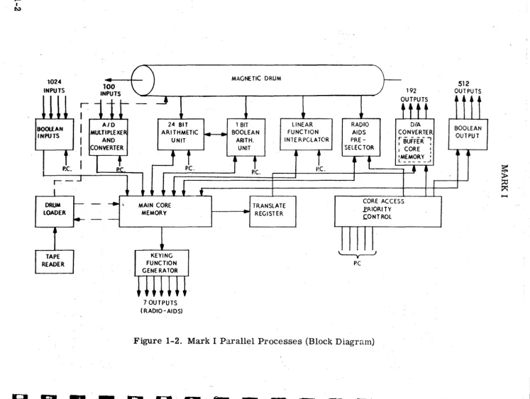
1-1.
O~NEftA:L.,The
Mark
Icomp~ter
(figure
1-1),operate. accorclln; to a
written program stored on a magnetic
drum.
Tbe instructions conStitutlng
a
~ypical
flight simulator'program ar,e' stored on the tirulX\,;us'lng a paper tape reader
a.nd drum loader, in;the order inwhicbthey,p-e to be performed. In tbis way,
dur-blgthe operation Of ,the computer, the,se instructions are read and perforzned in
the order in which they were wl'itten wlthoutwaitlng and without the necessity of '
addressing the location of the next lnstruction.
, ' ''
'
1-2.
Ifan instruction
is
readlndicatln1
an
arithmetic operation, this operation is
performed in the maina,rlthix)etlc:unit. This unit cQntalns the registers and logic
circuit;ry for pe,rforminga\larlthmetlc tJperatioI)s. Similarly, il1structions
indi-cating BoOleanoperatlons are performed in the Boolean arithmetic unit. The
source of, all nUmerical and Boolean data words for'these operations is the main
core memory,afasi, random .. access 'storage unit that serves
as,
the working
memory
ofthe
~arkI.
'
, .... . ' . . . , .
1~3.,The Mark,I,a1801nc~ude8a 18,384
word 11neat lnterpolatorthat operatesln,,'
parallel with the
malnprogr~to generate
in.tantalieO~.values ofthe
many
.
complex' functions encountered in aircraft flight .nd enginecomputat10n.. These
funetlOnl
are
con~tantlybetngcalculated, recalculated,
andstored 1n preassigned
memory 10cat10ns in the ma1n core memory for use by thema1n. program. ' Slnce
tbis is a parallel operat,lon, thare1s no time lost lnthemain program calculat1ng
.these q u a n t i t i e s . '
. , ,
" '
1-4 •.
!nthe Mark Ilnputsystem,
analogand Boolean lnputsfrom the outside
world (l.e., simulator controls) are written mto preassigned core' memory
loca-tlons, where .. they
maybeused
bythe malnprogram.
Theoutput system reads
calculated analog
andBoolean data out of core memory to activate simulator.
equip-m.nt. ';rhese systems allo operate in parallel w1th the main program, eliminat1ng
the need.for program·tlme to ach1eve.operations •.
1.8.
Also operating 1np81'allelw1th the main program
1~a rad10
pre-selection
unlt~Th1a un1t compar.s the 10cat10n
ofthe aircraft and the frequency
to whlch:eacboflt. I',c.elver.l,tunedw,lt,hthe locatlOft'andfr"'lency
ofS50poe.lbla radlo,t:r . .
m.lttlr.~..
1t~~'D\.electl the :be.tposl1bletransmltter,
U . .an),.
that
~.~h.rec.lv.r'
.bO\Jldbe:p~clct.l1l,llp,·lIldstor'"
n\l~e;rlcaldatacon- "
qernlnl thl .elected
·t:tan.mltt.r'lnpr'lI~lBl\edco:r•. :memof:)' loeat10na for us •. · .
by the malo prograDl.
81n~e,tbl.1"a.parallel .. operatlon, there ,1. lIa1n no Ume
taken up in them.,inprogram. ,";
.. ... , '
,,,"
. '''I i-8.
'lg~re
1-2 18 a
.i~plUied
blockcllqram of the varioul processes
within the Mark 1.
.
1-1'
...
I l.\)
",..""
"
100
"
/INPUTS
~1-t
-
Jl]J]
~ ~ ~
I
AID 24 BIT 1 BIT LINEAR RADIO D/ABOOLEAN
MULTIPLEXE~ ARITHMETIC BOOLEAN FUNCTION AIDS CONVERTER INPUTS
I
AND UNIT ARiTH. INTE RPGLATOR PRE - rB"UFFER -.·SELECTOR I ,
I
CONVERTER UNIT I CORE I1
t
1
l
t
'MEMORY' ,I
I
1c.
i
1
~ L ______ •Poe. p.e. Pc. p.e.
•
~r - - J
1
l
I
•
t-- - . . . MAIN CORE CORE ACCESS
DRUM TRANSLATE
.fRIORI TY
LOADER MEMORY REGISTER CONT ROL
~--~
TAPE KEYING '----y----J
READER FUNCTION PC
GENERATOR
t
~~~~~~
7 OUTPUTS ( RADIO - AI D S)Figure 1-2. Mark I Parallel Processes (Block Diagram)
-
-BOOLEAN OUTPUT
~
~
::0 ~
[image:13.794.38.785.33.595.2]!~.,,~ 4~_ s,
,-I
I
I
I
.,',I
I
I
I.
I
I"
'I
I
I
II
.
I
"
,I'
I
I
MARK I
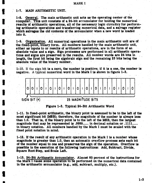
1-7. MAIN ARITHMETIC UNIT.
1-8.
Oeneral~
The Ill_ln arithmetlc ullitacts as the operating center
of~e
"
cQmputer ...
1;bll
llnit
con8ist8ofa24~bitaceumulatorforholdlng the numerical ,"
results 'Ofartthineticoperatlons,all of thenecessaryloglc circuitry for perform- "
, ing' arithmetic C)peratlonsand transferrlng numerlcaJ.data,· and a salvage reglster ,
whiCb 'salVage'.the old 'contents of the,
,~cu~\1l~tor w~en.a new
w~rd ~s,lQa&.rd
into it.
1-9.' Orjanization. AU numeticiuoperation81nthe malnarithmetlc unit are of
the fixea..polnt, binary form. ,All numbers handled by the main arithmetic unlt,
eitheras'inptits to or resultsofarlthmeUc operations, are 1n the form
ofan
absolute value and a sign. Sign processes'are performed in allarlthmetic
opera-tions
~diignsflfei,preservedin the
re~u~ts~.,l\llnumber words are 24 b,it., in
'length, the
.flr,t~.~being the,
~ebralcsign and the remaining 2S bits' being the
. 'absolute". value
pf
the
binary number.
'
l;'io~lf
the signbit ls a zero, 'the number is positive;
ifit is a one, the number i's
negative. A typical numerical word in the Mark lis shown ln figure l-S.
..
O· 0 ! I
0
,I 0 .10
I0
I 0 I0
I 0 I 0 I0
,I 0 I0
fl.
v JSIGN Blr.(+ )
'23 MAGNITUDE BITSFigure 1-S. Typical 24 .. Bit Arithmetic Wor,d
1~11~In
fixed-point arithmetic, the binary point is assumed'
to'
betotheieftot the
inost s1gniticantbit(MSB); the'refore, the magnitude
of t~enumber
isalways less
than
1~0.Thatis.1f,the binary point is to the left
ofthe MBB, then the largest' .
magnitude that may,be represented
is.9999 ... in decimal notation or .1111 ...
in binary notation. All numbers handled by the Mark I must be scaled with the '
fixed point notation -in. mind.
1-12.
Ifthe result
Ofany arithmetic operation in the Mark I1s a number whose
magnitude is greater than 1.0, then
an
automatic overflow process sets each bit
of the number, equal to one, and pre8erve.tlle 'sign
ofthe operation. Overflow is
possible in the execution
ofthe followingin.trucUons: Add, Subtract; Divide,
Square Root Step, and Scale L e f t . '
,
1-13. 24 .. Bit ArlthmetlcAccumulator.Almost 60 percent of the instructions for
the Mark
I
eausesomeoperatlon to
be
performed on the numerical data c'ontained
in the, arlthmetic accumulator
. , ' (e.g.,ad~, " , I ,subtract, multiply. etc.).
' [image:14.620.0.612.30.769.2], .
I:
, ,
" , ,
,
,
, ~
i
:1
!I
I
I
i
MARK I
i-14. The bit toibe left of the binary point in the accumulator is reserved
as a
e
sign bit. This bit gives the algebraic sign of the number defined by the remaining
23, bits-zero for
a
positive number, and one for a negative number ~I
1-15. Numerical data may be loaded into the accumulator from the core memory and, by virtue of a special instruction, from the drum. Data contained in the accumulator may be stored only'in core m'emory. . . . .
1-16. Most. operations performed on data in the accumulator may be initiated and finished in one machine cycle (6.105 microseconds). A few of these operations (e.g., multiply or divide) require several machine cycles to complete; therefore, once initiated, care must be taken that no new instructions arrive requiring op-erations on data in the accumulator until the previous, more lengthy operation has been completed.
1-17. 24.l.Bit Salvage Register. Associated with the arithmetic accumulator is
a salvage register,
24
bits in length. If an instruction is read that directs a data word be loaded from some source into the accumulator, whatever data happens to be in the accumulator at that time would be lost when the new word is loaded. Itis the function of the salvage register to store the data word which has' been in the accumulator prior to a "LOAD" instruction. Hence,. if the number X is in the accumulator at the time an instruction is read directing that Y be loaded into the accumulator, then one machine cycle later Y will appear in the accumulator and
X will appear in the salvage register. The previous contents of the salvage register will be lost.
1-18. The salvage register is
an
addressable location (0000). That is, it may actas a source of data with which to perform arithmetic operations on the contents , of the accumulator. However, the salvage register may not be addressed for
a
"LOAD"
instruction.1~19. MAGNETIC DRUM.
1-20. General. The drum of the Mark I contains sixteen bands of instructions , and constants. Once this information has been written onto the drum the "write'" , equipment may be disconnected and no further information can get into the drum. The design of
the
Mark I deliberately prevents any further writl'ni on the drum or 'modification of information contained on the drum. ' '1.21. Once the computer selects a band of instructions to read, then every word on that band 11 read 1n order, at a rate of one, word' every mach1ne cycle, until all the, words on that band have' been read. At this time another band is selected and all
or
those words are read, etc. As each instruction is read, the operation Itindtcates i~ performed. If the Qperation requires more than 8.106 microseconds 'to complete, it is then necess~y to make the immediately following instructions
no~operation in~tructions (NO-OP), untll enough time 'has been allowed to complete
the operation.
1-4
I
I
I
I
I
I
I
I
I
I
I
I
I
I
e
C
I
I
I
I
I
I
I
I
I
I
I
I
I
I
I
I
I
~I
I
MARK I
1-22. The 16 bands on the drum are made up of 240 data tracks, each track being one bit wide and 4096 bits in length around the circumference of the drum. Thus, there is a total storage capacity on the drum of over 983,000 bits. The drum rotates at 2400 RPM and requires 25 milliseconds to complete one revolution.
1-23. All of the bits comprising a word are read in parallel (e.g., if the first word
in a band of the main program were being 'read, then the first bit in each of the 16 data tracks making up that band would be read simultaneously). The read rate of the drum is approximately 164 kilocycles or 6.105 microseconds per word, ena-bling all words in a band to be read in one drum revolution.
1-24. Of the 16 bands of words written around the drum, (figure 1-4) 11 are for the general program, four contain instructions and constants for the linear
interpolator, and one is for radio aids.
2 3 4 5 6 1 8 9 10 II 12 13 14 15 16
GENERAL PROGRAM BANDS DIGITAL \
INTERPOLATOR RADIO AIDS
BANDS
BAND
Figure 1 .. 4. Magnetic Drum
1-25. All of the words in the general program portion of the drum are 16 bit words. There a,re over 45,000 possible words for this portion of the drum (4096 words per' band x 11 bands). The four bands of the digital interpolator portion
are m~e up of 11-bit words at 4096 possible words per band. This gives a total
of over 16,000 possible words in this section. The 4096 possible words on the r,adio aids band are all 20-bit words.
1-26. Each time the drum makes one revolution, three bands of instructions and constants are read simultaneously; one band is read and performed by the general
program section of the computer, one band by the digital interpolator, and one by
the radio aids band.
MARK I
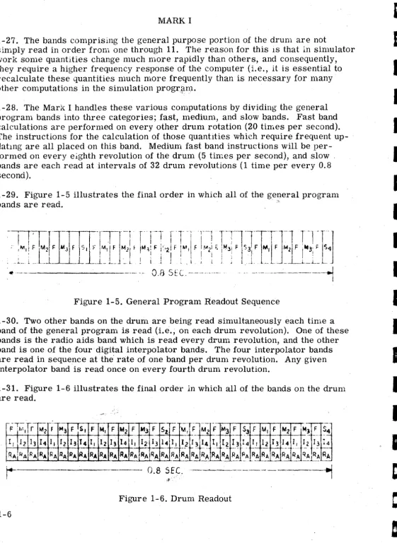
1-27. The bands comprising the general purpose portion of the drum are not
simply read in order from one through 11. The reason for this IS that in simulator
work some quantities change much more rapidly than others, and consequently,
they require a higher frequency response of the computer (Le., it is essential to
recalculate these quantities much more frequently than is necessary for many
other computations in the simulation progr~m.
1-28. The Mark I handles these various computations by dividing the general program bands into three categories; fast, medium, and slow bands. Fast band calculations are performed on every other drum rotation (20 times per second). The instructions for the calculation of those quantIties which require frequent up-datIng are all placed on this band. Medium fast band instructions will be per-formed on every eighth revolution of the drum (5 times per second), and slow. bands are each read at intervals of 32 drum revolutions (1 time per every 0.8 second).
1-29. Figure 1-5 illustrates the final order in which all of the general program
bands are read. ,.
.
,,---_.
o.a
SfC,···_·_-_··-Figure 1-5. General Program Readout Sequence
1-30. Two other bands on the drum are being read simultaneously each time a band of the general program is read (I.e., on each drum revolution). One of these bands is the radio aids band which is read every drum revolution, and the other band is one of the four digital interpolator bands. The four interpolator bands are read in sequence at the' rate of one band per drum revolution. Any given interpolator band is read once on every fourth drum revolution.
1-31. Figure 1-6 illustrates the final order in which all of the bands on the drum are read.
r-Fl~;,fr-M~r-;
M3 F Is, Ft.1~
F t.12 F MJ FIStF
\1
. . r--r-'
1j112 ]3 14 1,1 2 13 T4 I, 121314 I, 12 1314 I, I
- - 1
--RAjRA RA RA flA RA PA RA RA RA RA RA RA RA RA RA RA R
-_.- -
-jM2 F M3 F $3 F M, F M2 F
!I4 I, I2 I3
--
14 I I 12 13 14 I I.. _. ... . - --- .. -_. . ..
-RA .RA R~ RA PA RA RA RA RA RA
' - -
--
~----
.-.-:.- - - 0.8 SEC. ...
-.~---Figure 1-6. Drum Readout
1-6
I
I
I
I
I
I
I
I
I
I
I
I
I
I
I
[image:17.617.40.602.23.792.2](.
I
I
I
I
I
I
I
I
I
I
I
I
I
I
I
I
I
I
MARK I
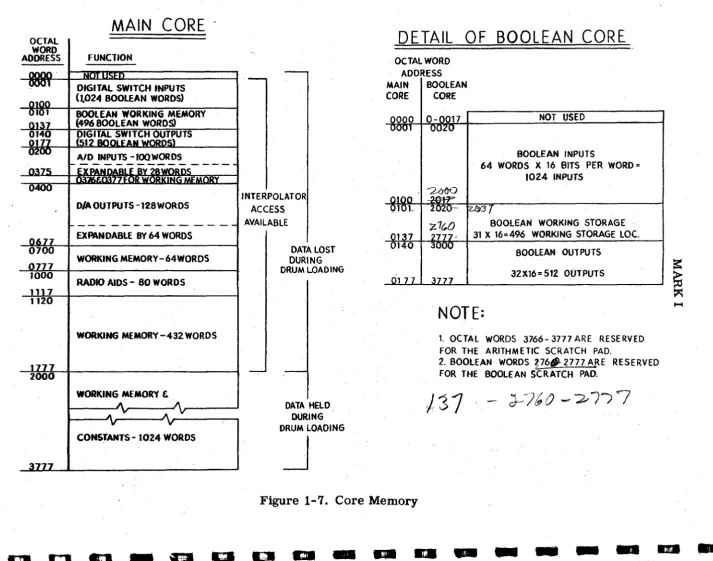
1-32, CORE MEMORY.
1-33. General. The core memory of the Mark I is a 2048 decimal word~ random
access mempry~ each of whose 2048 decimal words is an addressable location~
Numefical information may be stored in any word location or the information· contained in any word location may be read out on command (non=destructive
readout). Only one word location in the core may be read out of~ or written into
during any given machine operate cycle (approximately 6 micro-seconds). Each
word of the main core is 24 bits long~ of which the most significant bit is the
sign bit.
1=34, It is the function of the main core memory to act as the working storage of
the computer. That is» all quantities stored in the main core can be changed9
up-dated~ erased» etc 0 .
1-350 All the variables in the simulator system equations are each» individually~
assigned locations in the core storage» and as each of these variables is re=
calculated)) or changed» the new value is llnserted into the proper core location),
thus replacing the old outdated value. All inpu.ts to the Mark I computer from the.
outside world (e.g. cockpit~ instructori s station) come to preassigned storage
locations in the main core. All outputs from the Mark I to the rest of the simu= lator system are read out from their preassigned storage locations in the main core. Independent variables which are used by the linear interpolator for the purposes of function generation are read from thefr assigned location in the core
mem0R'" The linear interpolator also stores computed functional values. [f~)>>
f{X» Y~ » in preaSSigned core memory locations. Figure 1~7 shows the :core
locations for the various quantities stored in the core memory. .
1=360 All mathematical quantities that are needed for a simulator progr~m (with
the exception of constants which may be stored on the drum)>> are soored in ClOre
memory.
1-37. Priority. Only one word of the entire core memory may be interrogated or written into during anyone machine operate cycle. The many parallel processes
of the computer (function generat],on~ radio pre=selectionjl fnput=output readingjl
main program arithmeticy etc.) all require memory access. It becomes nec=
essarYll therefore that these variou.s processes be given a priority ratingo
Any operation of the main program requiring memory access takes first priority 0.
Any operations or instructions in the main program that do not require memory
access are consil.dered to be "holes" in the main program and it is during these
~
I ClO
OCTAL
WORD ADDRESS
7
1000
117 1120
7
200
MAIN
CORE'
FUNCTION
DIGITAL SWITCH INPUTS
(1024 BOOLEAN WORDS)
BOOLEAN WORKING MEMORY
{496 BOOLEAN WOROS>
DIGITAL SWITCH OUTPUTS 12
D/A OUTPUTS -128 WORDS
EXPANDABLE BY 64 WORDS
WORKING MEMORY -64WORDS
RADIO AIDS - 80 WORDS
WORKING MEMORY -432WORDS
WORKING MEMORY &
CONSTANTS - 1024 WORDS
INTERPOLATOR
ACCESS
AVAILABLE
DATA LOST
DURING
DRUM LOADING
DATA HELD
DURING
DRUM LOADING
J
DETAIL OF BOOLEAN CORE
OCTAL WORD ADDRESS MAIN
I
BOOLEANCORE CORE
~
NOT USED
BOOLEAN INPUTS
64 WORDS X 16 BITS PER WORD =
1024 INPUTS
:3
BOOLEAN WORKING STORAGE
31 X 16=496 WORKING STORAGE LOC.
BOOLEAN OUTPUTS
32X16=512 OUTPUTS
NOTE:
1. OCTAL wORDS 3766- 3777 ARE RESERVED FOR THE ARITHMETIC SCRATCH PAD.
2. BOOLEAN WORDS ?,76t1-2777 A.RE RESERVED FOR THE BOOLEAN SCRATCH PAD.
)'J1
- (7-' "'\ '.}" /() (J?f -~/) ~....,"-,- ....7-Figure 1-7. Core Memory
II
I
==
~
~
....
~ ~ ~
. . . .
~
1:1
p c . -
. . . -
_ .. -
-
. . - /
[image:19.796.55.768.38.599.2]I
I
-I
J
I
I
I
I
I
I
I
-I
I
I
I
I
~I
I
I
. MARK I
"holes" that the auxiliary processes of the computer gain access to the core memory. Instructions in the main program such as SCALE, SHIFT, ABSO-LUTE VALUE, INVERT, ZERO SLICE, FLAG NEGATIVE, and NO-OPERA.., TION are operations which do not require memory access and thus act as "holes" to auxiliary sections of the computer. Priority for all of the parallel processes of the Mark I is as follows:
a. Main Program
b.Digital Function Iriterpolation c. Radio Aids Data Preselector
d. Analog Input Scanning e. Analog Output Scanning f. Boolean Output Reading g. Boolean Input SCal.?Jling
1-38. Boolean Storage. Of the 2048 words of memory in the main core, the first
128 words are reserved for use as Boolean storage locations. _ Only the first 16
bits in each of the 128 words is used for this purpose. This results in a total of
2048 bits of Boolean storage, since a Boolean. word is only 1 bit long. The com-puter is set up to appear as if there were two separate core memory blocks; one being
a 2048 word arithmetic core and one being a 2048 word Boolean core. (See figure 1-7.)
1-39. There is a separate Boolean arithmetic unit with its accumulator and
salvage regi_ter in which all Boolean operations take place. Like its counterpart, the arlthmetic core memory, the Boolean core memory acts as the working storage for .all Boolean operations. Boolean variables are assigned storage locations here. AU Boolean inputs from the. rest of the simulator system are re~into preassigned storage locations in this memory; and all Boolean outputs from the Mark Ito the rest of the simulator system are read·'Ou't from their assigned storage locations in
the Boolean memory. . .
-1 ... 40. Since the Boolean core memory -1s really made up from 128 words of the main core memory, then any instruction requiring access to the Boolean memory is accessing the main core memory. Any instruction of the main program which requires access, whether it is Arithmetic or Boolean, represents a "highest priority" operation.
-1-41. There is no protective circuitry in the Mark I to prevent using a non-Boolean
instruction to address the entire contents ofa Boolean storage location (the entire
--MARK!
16 bits of lOne of the 128 main core words)o H<owevelf~ if an attempt were made to
address the contents of the enUre bl())ck~ lit would be mean!ngless~
'n
the bits ,hadbeen used fOlr B(Q)oleanstc»rage pu.rplO)Se§~ to try to use it ln an ordinary arithmetic
operation 0 It is comceivable~ however ~ that this sort of Olperation may be
deliber-ately done in the case where it 1S desired to plt"ovl1.de a direct 16'=bit binary output
of an ordinary arithmetic quanUty wUhout g(Qlilng thrOlUlgh the Digital to Analog(D1 A)
converter Q In this case» the maln w«JJlt"d locatJi«JJD contadining the 16= bits concerned
'Would be "stolen" permanently from the BOOllean secUOllll fc»r use by the main
arithmetic unito Any' attempt now to wril.te BOlolean llnformaU((JJn into any of the 16
bits of the main word location concerned would desuoy the :meaning of the arith- .
metic quantity now permanently stored in that main core locationo Boolean $torage
locations may alsOl be stolen (in blocks of 16) fo:rr the purpose of storing an
ex-ternally coded~ 16= bit binary wo:rrd as a,n li[llputo
1-420 It is important»
n such operations as desclr'iood in paragraph 1-41 are
employed for the purpose of pl"Olviding direct binary inputs and outpu.ts of ordinary
arithmetic qU!.antities~ that the pr\Qlgrammer look on the enUre Boolean' core as
being reduced in size~ and must never address any (Qif the bUs clO!ncerned for any
Boolean purpose. «Again~ there is n(()l pr\Qltecti1.ve circuitry tID prevent the
program-mer from doing so.)
1=43. ANALOG TO DIGITAL CONVERTERo
1~44. GeneraL It is the functllon of the AID converter to take all of the analog
inputs to the Mark I (from cockpit» etco) and couvert them into 14= bit binary
number so There are 100 input Unes9 expanda,ble to 1280 Each of these inputs is
"Converted sequentially to bllnary and stored in its own individual core memory
location. This operation is a process which is calr'ried tOJn 1n parallel with the '
~ain program and is fully amtomatic 0 There is a block of core memory locations
containing the digital equivalent of the vari(QlU8 analog 11nput quantities necessary for equations~ and all that 11s l1"equ.ired by the programmer is to address the
appropriate core location to employ any of these quantities required in
computa-tion.
1~450 Scaling 0 All analog input quantities a:rre scaled in the range of minus 10
volts to plus 10 volts; these reference voltages being provided by the Mark I~ The
AID converter converts these numbers ttC» binary numbers scaled from minus one
to plus one.
1=46. Priority 0 The 100 multiplexed inputs of the AID copverter a.re sampled and
converted into properly signed 14=bRt binary wolt"ds in tWOl'drum revolutions. The
AID converter will sample inputs only dur:ling the fi1.:!I"st and thkd quadrant of each
drum revolution~ and the 100 AID channels are spread (Q)ve:r the four allowed
quarters of the two drum revolU!tions~ Sl) thalt appr:oximately 25 channels are
sampled~ conve:rted~ and stOlred in each aH\Qlwed quadranto A counter provides the core memory addresses in whl1ch each quantity Jis stm"edo
I
I
I
I'
I
I
I
I
I
I
I,
I
I
I
I
I
I
a
I
I
I
I
I
I
I
I
I
"I
,I
'I
I
I
I
I"
il
.
'I
I
MARK I
'1-47. Me~~l'Y, a.~cess is required for stOl' age , . and the A/D converter is under the
" control of the prior'ity circuitry. (Refer to paragraph 1-37 for A/D priority.)
When an input has been sampled, the binary equivalent is converted and held until
the next input Issampled. At that time the, first input is stored in the address
dictated by the counter. The counter is advanced, the next input is held and con-verted and the process continues unt11 all of the inputs have been sampled. The process repeats endlessly, and occurs without programming attention or instruc-tions. '
1-48. DIGITAL ,TO ANALOG OUTPUT SYSTEM.
1 .. 49. General. 'Oigital to analog,conversion in the Mark I operates in parallel with
the main program. There are 128 independent anaIOgoutputs tn the Mark I with
theabUlty to~xpand to 192outputs~ The analog outputs are used to drive indica;:..
tors, motion systems, recorders, etc. in the external simulator equipment.
1 ... 50 .• The equa~lQnsrepresenting each analog output quantity is implemented in
the general proS~.to be computed by the Mark I. A fixed word location in the
main core memorY'is reserved for each quantity, and as each quantity is recal ..
culated in the
main
program, its new value is stored in its respective memorylocation. TheQl<:lc~of"core memory locations which contains the analog output
quantities 1s up":dated twice every drum revolution and is sequentially transferred
to a buffer core\memory. The words in the buffer core are then fed to individual D / A
converters whose outputs appear as analog voltages representing the digital quantities.
1 ... 51. Storage lQc~t()nSl~ the malncore which
are
reserved for outputqu811tlttes 'are all 8a.aipledbj~itb.,J)uffer core at a rate of 80 times a second. The buffer core,
in turn, 188ampled'J~yt)1.e D/ A converter 80 times per second, which represents
the sampling rate of the Dj A output
system.
. 1 .. 52.
In
ordertha.t
amaxlmu.m
of 192 words in the main core memory be readinto
the buffer,core m.emory"193 8ep~ate memory accesses are required. All of
these wol1ls will be'acc~8,ed once during
the
second quarter of drum revolut1on,andagaln during
tlie.
fourUl
quarter of drum revolution. Since each word is readtwice durlng each drum,l'8volution (25 mUliseconds), the sampling rate 1s 80 Umes
per second. The drum plays no actual part in this process, but provides a time
balle for examtnlnsthe Dj
A
conversion. ''1-83. The
time
required to read each word 1s 6.1 microseconds (basic machinecycle), therefore one-quarter revolution of the drum represents Efh9Uih time for
1024' posalble memor), ICC.I.es. The Dj A converter has access to core memory,
only when the core m.~ory 1s
not
being accessed by either the main program, thedtgltallnterpolator or
the
dataprese,lector. 'There
must beatleast
,192'"holea", in the total acc ••• requirements on the main core memory during the
second and fourth quart.r. of a drum revolution or else all of the output words
, would not let , lampled. . ,
it
counter in the Mark I generates the core memory-~
MARK I
addresses of output quantities which are to be read into the buffer core. As soon . as the first address is accessed, the counter advances to the next address and holds that address until an opportunity occurs.to interrogate that word. The word is read into the buffer core and the counter advances again. This process contin-ues until all 192 addresses have been interrogated. . .
1-54. Although the word length in the main core is 23 bits plus one bit for sign, .only the sign and the nine most significant bits are read into the buffer core,
utilizing only ten of the available 16 bits per word. As words are rea4 out of the main core they are read Into a 12 btttranslatereiister .. Bits 10,11 and 12g0thrOUlh
a
warbler circuit to produce the rourid-off bit while bits 1 (20 ), 2 (2-1);
and 3 (2';' ) I:l'e d~vided by two and drive the vertical wires strung through the three most · significant and three. least significant bit posiUons of- all 192 words of the buffer .core (see figure 1·'8). The remaining b1t~ drive the vertical wire, which is strung · tFough the corresponding bit positions .of all 192 words of the buffer core.
1' ...
55. BOOLEAN ARITHMETIC UNIT.· .'1-58. General. The . Boolean arithmetic unit is the Boolean counterpart of the main' . arithmetIC unit. It 'is the purpose of this. unit to perform all Boolean operations
'Indicated by instru,cttons in the general. pr:ogram.· The logic circuitry of the Boolean arithmetic unit is ~ranged to perform the . functions of "ANl)" (mu,ltlply), "OR" I
(~m),~'lNVERT" (compliment), "LOAD", and ''STO.KE''. As in the main arithmetic
~nit(paragraph 1~7), the Boolean arithmetic unit also ·has an accumulator and a
:e:alvage register. Boolean wo~ds are one bit in length, and the accumulator is a
. > 'one bttr~lstEtr wblch Is used to. hold the results of all Boolean operattons.
,:~otean·.· words tnaY:b& loaded into the Boolean accumulator from the main core,
'and information in the Boolean aecumulatormay' be stored in memory locations
"in themaincore~
All
Boolean Operations indicated by .instructions in the general. p~ogram 8l"e. periormedon the cori.tents of. t~e Boolean accumulator by the contents
~~ the address specified in the instruction.
1 ..
57.
SalVage Register. The Boolean salvage register performs the same function' as the.salvage register of the main arithmetic unit (i.e. to salvage the previous . contents of the accumul"tor when a new word is loaded). Unlike the main arith..;.~et1c salvage register,: which is only a one-word register, the Boolean 'salvage r,gister can hold four one~b1t words, all of which are addressable. By having a multi-word salvage register, this unit m~Y' act as an intermediate, temporary storage·unit, thus reducing the core memory ae.cess.requirements of the Boolean arithmetic unit.
1-58. For the purpose
of
explaining the operation of the salvage register, consider the sequence of events as a series'of several"LOAD"
instructions read off the drum (this is a most unlikely series of instructions). Assume the Boolean quantity .A is in'the accumulator when an instruction directing that the quanttty B be loaded.is read. ' . .
1-12
I
C
I
I
I
I
I
I
I
I
I
I
I
I
I
I
·1
;
~ .45
I
I
I
I
I
I'
I,
I
I
,
I
I
I·
I
I'
I
I
I
I
44 l _:Z;::::;:;
..--~ ..--~.
~ ' -1m
.~1"'""'1
,1
0
MI
J
L
I' ..
/rl:>°NIN
' - '
,~ ...
q
I'"
:-t:>r ...
1
N
--V-~IN
~,...
-~-J
~ ~,.
Q
-N
...
~"N
~
0- ~-
v.-i
CO..-IN
V
-
,....
-"fool
I
~ ~1' I~ ~
... N
..
-
'YT
N ."'"'"
~~'N
~ I"'"'"
~
\.?'"~IN
." ~
-'VT
N1N ..N
I""-
1.1'---
ro-. """ONIN
.C,...
-, ,
. MARK 1
r
, ,!
"
'.,""
f' I' 1" "- '\..
".
i' I ' "
"
"- ' \ ."
f' I'\. "- \.. ..
I' !'
I'
'"
\."-i'
i"
. r,
'- \.. \..
~
f'.
'f'
"
\.
'-f'
.. f'\ 1"'\"-
,
\.I'
"
~"\.. "-
'-"
!, ~\. . " .... f' f'
"
\. .'-.. ....
1'\
"
I''-
,
\.. , ,"-I' r\.
"- "-
'-i ' I' 'f'
' ,
"Lt
N4
.n ..~
-
..c
I
II
'.
I..
..
"
I'
"
,
"
I ',
I' "-I' " I',
I ' ' .,.
I',
I'"
I'"
!'\...
"
',-I' ,~,
I"
Q;
.,
-.J
II
~."-"
l
I
i . . " ' .
Instruction .
LoadB LoadC
LoadD
. Load E
Load F
. MARK!
. Contents of !9cumulator
A B C
D E
F
Boolean Salv~e Register
0000 000 1 0002 0003
-A B C
D E
A
B
C
D
A
B C
A
B
1-59. The four words of the Boolean Salvage Register have addresses 0000 throUgh
0003 and the contents 'of any of these word locations may be used to perform a
logical "AND" or "OR" with the contents of the Boolean accumulator. That is, they
are addressable locations." The contents of any of these salvage register locatlons
may be "loaded" into the Boolean accumulator. • However, the contents of these
locations may not be stored in the Boolean core. Only the contents of the
accumu-lator may be stored in the core memory.
I
1~60.DIGITAL LINEAR FUNCTION INTERPOLATOR.
1-61. General. Function generation in the Mark I is a process which is done
continuously, in Parallel with the main prOgram of the machine, and thus, b~cause
of the saving of computation time in the main program, contributes l~gely to the
'. real-time dyilaJ:nic response of the Mark I. Function generation is accomplished
by mearrS of linear interpolation between the ordinates of fixed "breakpoints"... .
Figurel 1-9 illustrates an' arbitrary fUnction of X whose X axis has been divided .
. into eight equal segments'.· These eight segments are defined by nine breakpoints:
0, 1/8, 1/4, 3/8, 1/2, 5/8, 3/4, 7/8, and 1. . ' . .
1-14
,
I
f(X)
11'
I1
I II
If(-e')
If(t)
FCc)
II
L.:.:
~~---+----+--+---+-r--I'
1
.J.
s ·
~ "T A' e' J... .:. 2. Q i 4 ~ 8. 10 •o
- " - - - X
Figure: 1 ... 9. Linear Function Curve
I
C
I
I
I
·1
I
I
I
I
I
I
I
-
I
I
·'·1
I.
I
I
I
I
I
I
I
I
I
I
I
I
I
I
I
I
I
I
I
. MARK I
1'-62. U the ordinates of these nine breakpoints are known, (e.g., f (0), f (l/8), f
(1/4), f (3/8), etc.) and if the independent variable X is known, then it is possible to perform a linear interpolattonto determine f (X). For instance, if X.l1es
be-tween 1/8 and 1/4 then it is possible to interpolate bebe-tween f (1/8) and f (1/4) to obtabl a very close approximation of f (X).
1-63. Tile linear interpolat~r has its own arlthmetic unit with a parallel binary adder arid the appropriate registers and logic circuitry to do interpolations.
" ,', I •
1-64. Scaling. All numbers handled by the Mark I must
be·
scaled so that the magnitude is not greater than one. This also applies to the function interpolator. Therefore, both the independent variable, X, and the ordinate value, f (X), must be scaled sO that their magnitudes are not greater than one. All numbers handled by the interpolator are assumed to be positive, so variables and functions must bescaled accordingly.
I
1-65. Flow Of Information. The four bands on the magnetic drum which are used for function Interpolation serve the purpose of storing the ordinates of the break-points of all the function curves. The drum also contains the core memory location of the independent variable, and the core memory location in which the calculated value of the function will be stored. Each different function is represented by its own block of information listed on one of the bands, all of the blocks being listed in order around the bands. Figure: 1-10'shows the flow of information for function
g e , p e r a t l o n . ' .
MAGNETIC
DRUM
---
lit•
...
MA'N CORE
MEMORY
LOCATION OF X
f(O)
+
f(I.O)
LOCATION OF f(X)
f(X)
X
~
-LINEAR
INTERPOLATOR
•
Figure 1-10. Flow of Information (Interpolator)
MARK I
1-66. It is unnecessary to store the X values of the breakpoints because, sin~e
these breakpoints are fixed at 0, 1/8, 1/4, etc., it is only necessary to build the.
logic of the interpolator in such a way that it can look at the value of X and ,
recognize between which two breakpoints it lies. Consider the binary representa-tion of the numbers, 0, 1/8, 1/4, etc. '
o
=
000' 00000001/8 = 001'0000000
1/4 ='010'0000000 3/8 = 011'0000000 1/2 = 100'0000000
5/8 = 101'0000000
3/4
=
110'00000007/8
=
111'00000001
=
111'1111111 '1-67. An examination of only th:~ first three digits of X will determine between which two breakpoints X\U~s~
fiX
<
1/8 then itsiii'st
three dtgltswtll be 000;hence 0 S X
<
1/8. If 1/8 ~ X<
1/4, then the first three digits will be 001.Figure 1-11 shows how the first three digits of X will determine between which two breakpoints it lies.
000
001o
I4
010
OU
J. 2.
100 101 110
"I
1.0
Figure\1-11., Decoding Scheme Determining "Location" of X
1-68. In a block of words on the drum concerning a given function (assume a func-tion of a single variable), the first word that is listed Is a control word which
serves' the purpose of identifying a new function and describing whether it is
a
func-tion of one, two, or three variables. The second word listed is the memory locafunc-tionof the independent variable. Following this will be the ordinates of the nine break-points in order beginning with f (0). The memory location of X, the independent, variable, is listed before the ordinate information. Memory access by the main program has priority over access requirements by the interpolator; therefore, the interpolator may have access to memory only during "holes" in the main pro- , gram. In order to ensure that the current value of the independent variable is obtained from its memory location, its address must be repeated five times. (One of the rules governing the general pwpose program is that memory cannot be accessed more than four times in a row or more than 60 percent of the program.)
1-16
'~---a
e
I
I
I
I
I
I
I
I
I
I
I
I
I
I
D
I
I
I
I
I
I
I
I:
I
I
I
'I
I
I
I
I
I
I
I
I
.}lARK I
. , ,
,1·69., 'Once acces.sto the'c'ore memory bas been gained, the current val"e of the
bidepend~ntvarll.blelsread into a register in the interpolator. The first three
, dlgi~s of X(tll~.1n~p.nde~t vari~le)
are
examined to' bracket X betwe.en twobr.eakpoints.Thlsprocess Is completed ~fore. the data field 1s read off; therefore, before the f1rst()rdlnateis read, the interpolator already know. '?1lh'1ch two break-"points brac~et.X. •. '" ~ ... tlle ordinat,es are read off the drum, only, the two ordinates
concer~ed;J(~,~clf(Xn+l), are held for lnt.rpolatlono, The otbei' ordinate "
wordsare 19norec:tbythelnterpolator. The result of the interpolation is f (X).
f(X) is held 1ntbe, Ilnear interpolator until a word 1s read off the drum directing
that' f (X) be stored andgivlng the. loca,tion in the c.ore memory in which tos.tore it. The location off.(X) must also be. repeated flve. times to ensure ~emory access. 1-70. Tlmm.Inthe,event that X was l~cated between '1./8 and 1.0, the.interpola-tor wOula ' :ve.to w-.lt until tbe eighth ana:nlntb ,ordinates were read off. tbe dru.m
befor~ i~could begin Its calculations. This means that some time must be allowed
aft.r the last ordinate is listed before, the memory location of f (Xl is 11sted •. ·This ,UJ:P.eis
to
allow the, interpolator. to fillllh .lts calculations. before dlrecttq.it. tostore. the, results. "
1-71. In'the case of a single variable function, L(X), two blank words (13 U8C. "
approximately), allows suffiCient time for the rinterpolatQr~tonn[sli IfscafcU:;-'--lations. In the case ofa function of two variables (X, Y), four blank words are necessary. and, for the three variable function (X. Y. Z), six blank words ate necessary.
1-72. The final arrqement for the data and instructions for some Single variable function
(Xl,
is,Shouin figure 1-12. ', '.
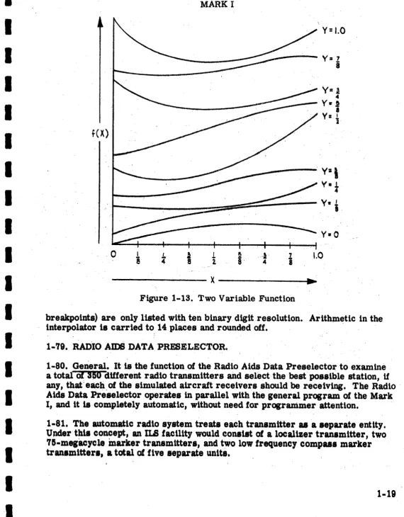
.1-78.1'110 Vliiab1e ,Punc.tio,2. " A'" function of two variables as handled 'by the Mark I
wiUbi
lDliformOf
a !'family·' of nine single-variable functions.' (See figure "1 '13) I . '
-, ',_J ""," '
1-74. Todescrlbe
atwovar.1able
function requires 81 ordinates. The address ofy is 11IJted~.rU.sttngthe address of X, and must also be repeated five. times; to'
ensurem~mpryacce8s. The.81 data.points are listed in zoneflvebeginning.
with
the f (X,'!'; =O)cur,ve'and ending with the.f (X, Y .. 1:1 1) curve.
-1-'15. 'TherewoUldbea.total of 729 data words fora three variable. function: nine data words tor]C, times. nine data words for Y,. times, nine data words lor Z. The . address Ipcatlon.~tll.e ind$pend.nt variable' Z 1s listed after the Ylocation and
.must alio ' . be, llsted flve times to ensure memory access. . . . . ' . . .'
, ' 1 , ." ' . .
1-7e~ Siilce,t"re,ar.,fou~bands,onthe drum for the linear interpolator ~ 4098
words