© 2016, IRJET | Impact Factor value: 4.45 | ISO 9001:2008 Certified Journal
| Page 250
Aerodynamics of Winglet: A Computational Fluid Dynamics Study Using
Fluent
Rohit Jain
1, Mr. Sandeep Jain
2, Mr. Lokesh Bajpai
31
PG Student,
2Associate Professor,
3Professor & Head
1 2 3
Mechanical Engineering Department
1 2 3
Samrat Ashok Technological Institute, Vidisha-M.P.
ABSTRACT:T
he main objective of this paper is to study the effects of winglet on aerofoil NACA 2415 using CFD. This is to be done by comparing the aerodynamics characteristics which include Drag coefficient (CD), Lift coefficient (CL), and Lift to Drag ratio (L/D) of with and without winglet model. Induced drag can be reduced by using wing-tip device like Winglet. Spalart-Allmaras turbulence model is used for better accuracy around the boundary wall of wing. The geometry of wing models and meshing are carried out by ANSYS 15 software. The computational simulation is carried out by ANSYS FLUENT with low Mach number 0.23 at various angle of attack. The aerodynamic characteristic of wing with and without winglet are to be measured and compared for best aerodynamic characteristics.KEYWORDS- Angle of Attack, Winglet, Lift and Drag Coefficient, CFD
1.INTRODUCTION
A winglet is a projection on same material at the wing tip or end, is used to improve the efficiency of aircraft by lowering induced drag. It may be vertical or angled extension at wing tip [1].
There are many factors which influence the amount of aerodynamic drag which include shape, size, inclination of the aircraft with the flow and conditions of the flow passing the aircraft. In flight, a lower pressure is to be found on top surface and higher pressure on bottom surface because of Bernoulli's principle which in turn sucks the aeroplane into the air [1]. During the flight, vortices is formed at the wing tips. The wing tip vortices produce a swirling flow of air behind the wing which is very strong near the wing-tips. It decrease the lift force. For reducing these vortices near the wing-tip, winglet is used that produce less vortices with increasing the lift
force[2]. Winglets allow for significant improvements in the aircraft fuel efficiency, range, stability, and even control and handling [3].
Fig. 1 : Wing-tip Vortices
The concept of winglets was originally developed in the late 1800s but in 1897, British aerodynamicist Frederick W. Lanchester, who patented an idea that a vertical surface (end plate) at the wingtip would reduce drag by controlling wingtip vortices [4]. It was not in used in practices because of skin frictions and flow separation that was increasing the drag.
© 2016, IRJET | Impact Factor value: 4.45 | ISO 9001:2008 Certified Journal
| Page 251
aeroplane or aircraft [5]. Small and nearly vertical fins were installed on KC-135A and flights were tested under condition in 1979 and 1980. Aircraft designers were searching for methods to improve the overall efficiency of the aircraft’s wing which would be beneficial for both the aircraft manufacturer and the airlines.
In 1994, Blended winglet was developed by Louis B. Gratzer [6]. Aviation Partners Inc.(API) had developed an advance design of winglet to reduce the nosiness of the drag due to sharp edges. Later, Wing Grid concept was developed by La Roche from Switzerland in 1996 and got the clear for his invention to reduce the induced drag. Aviation Partners Inc. (API) and the Boeing Company made advance partnership in 1999 for the design of blended winglets. Hence winglet designs were formed for developing to overcome the drag of the wing[6,7]. Research is still going to reduce drag with modification of winglet design by changing its shapes. Winglets are currently used many aircrafts like the Boeing 747, Boeing 737, Airbus A-319, Beechcraft, Learjet 60 etc.
2.METHODOLOGY
CFD investigation consists of three stages. Starting from pre-processing stage where 3-D geometry of wings model were drawn using ANSYS Design Modular and the grids were generated by ANSYS ICEM-CFD. The second stage was simulation by FLUENT solver using Finite Volume Approach [8]. Finally, third step was the post-processing stage; in which the aerodynamic characteristics like Drag coefficient (CD), Lift coefficient (CL) and Lift-to-Drag ratio (L/D) were defined at the various angle of attack for wings.
2.1 Pre-Processing
Geometry and Meshing of wings are created in pre-processing.
2.1.1 Geometry
3-D geometry of Boeing 737-700 scaled wing were drawn using ANSYS Design Modular [9,10] with aerofoil NACA 2415. The chord length of aerofoil used 100mm for profile (root) and 18mm for wing-tip. Total span length was 177mm with dihedral angle 60. Winglet was attached with wing NACA 2415, that’s height was 35 mm.; was also drawn with ANSYS Design Modular. Other wings with winglets like Wing with Winglet Modified profile (root), Wing with Winglet Modified dihedral angle and Wing with Winglet Modified profile (root) & dihedral angle were drawn in ANSYS Design Modular.
Fig.2 : 3-D Model of Wing With NACA 2415
Fig.3 : 3-D Model of Wing With Winglet NACA 2415
2.1.2 Meshing
© 2016, IRJET | Impact Factor value: 4.45 | ISO 9001:2008 Certified Journal
| Page 252
Fig. 4 : Meshing on Wing NACA 2415
Fig. 4 : Meshing on Wing with Winglet NACA 2415
2.2 Solver
The numerical simulation by the solver was done after the completion of the mesh generation on fluid flow and wing. The solver formulation using as turbulence model Spalart-Allmaras was used because of low Mach number with one-equation turbulence model that provide superior accuracy around boundary wall [10]. After selecting turbulence model; boundary condition, solution control parameters and material properties were defined. All the parameters were specified for various angle of attack, then the model was initialized with inlet values then Run the calculation for some iterations for flow parameters.
Properties of Air : constant
Density: ρ = 1.1768 kg/m3 Viscosity: μ = 1.716e-05 kg/m-s Pressure: p = 101325 pa Mach Number = 0.23
2.3 Post Processing
After simulation, The aerodynamic characteristics were found for all wings. The details are given in subsequent heading of with Tables 1 to 3 and Figure 8 to 10.
3.RESULTS AND DISCUSSIONS
The aerodynamic characteristics of 3-D scaled wings models likes Wing NACA 2415, Wing with Winglet NACA 2415, Wing with Winglet Modified profile (root), Wing with Winglet Modified dihedral angle and Wing with Winglet Modified profile (root) & dihedral angle were found in post processing with various angle of attack like 30,50,80,100 and 120.
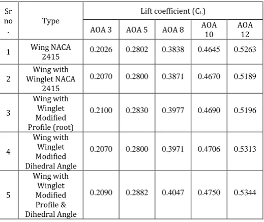
3.1 Lift Coefficient (CL) : Analysis for Wings
[image:3.595.37.284.98.238.2]Lift coefficient for Wing NACA 2415, Wing with Winglet NACA 2415, Wing with Winglet Modified profile (root), Wing with Winglet Modified dihedral angle and Wing with Winglet Modified profile (root) & dihedral angle were found in post process at various angle of attack. It is observed that the Lift coefficient (CL) increases with the increases of angle of attack (AOA) as shown in Figure 8.
Table. 1 Lift coefficient CL : Comparisonwith all Wings
Sr no
. Type
Lift coefficient (CL)
AOA 3 AOA 5 AOA 8 AOA 10 AOA 12
1 Wing NACA 2415 0.2026 0.2802 0.3838 0.4645 0.5263
2 Winglet NACA Wing with 2415
0.2070 0.2800 0.3871 0.4670 0.5189
3
Wing with Winglet Modified Profile (root)
0.2100 0.2830 0.3977 0.4690 0.5196
4
Wing with Winglet Modified Dihedral Angle
0.2070 0.2800 0.3971 0.4706 0.5313
5
Wing with Winglet Modified Profile & Dihedral Angle
0.2090 0.2882 0.4047 0.4750 0.5344
[image:3.595.34.285.268.410.2] [image:3.595.308.568.368.586.2]© 2016, IRJET | Impact Factor value: 4.45 | ISO 9001:2008 Certified Journal
| Page 253
Fig. 8 : Lift Coefficient (CL) at various angle of attack
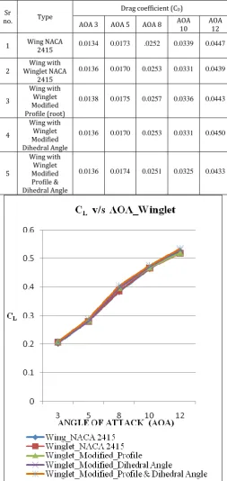
3.2 Drag Coefficient CD : Analysis for Wings
Drag coefficient for Wing NACA 2415, Wing with Winglet NACA 2415, Wing with Winglet Modified profile (root), Wing with Winglet Modified dihedral angle and Wing with Winglet Modified profile (root) & dihedral
angle were found in post process at various angle of attack.
[image:4.595.32.286.106.642.2]Table. 2 Drag coefficient CD : Comparison with all Wings
Fig. 9 : Drag Coefficient (CD) at various angle of attack It is observed in Table. 2 that the Drag coefficient (CD) increases with the increases of angle of attack (AOA) as shown in Figure 9.
3.3 Lift to Drag ratio (L/D) : Analysis for Wings
[image:4.595.304.562.179.481.2]Getting all Lift coefficient and Drag coefficient of all wings at various angle of attack, is found that L/D is increasing with increasing angle of attack up to 50 and after 50, L/D ratio is decreasing with increasing angle of attack. Highest value of L/D ratio is found at 50 angle of attack as shown in Figure 10.
Table. 3 Lift to Drag ratio (L/D): Comparisonwith all Wings
Sr
no. Type
Lift to Drag Ratio (L/D) AOA
3 AOA 5 AOA 8 AOA 10 AOA 12 1 Wing NACA 2415 15.13 16.19 15.25 13.69 11.77
Wing with
Winglet NACA 15.26 16.24 15.30 14.11 11.83 Sr
no. Type
Drag coefficient (CD)
AOA 3 AOA 5 AOA 8 AOA 10 AOA 12
1 Wing NACA 2415 0.0134 0.0173 .0252 0.0339 0.0447
2 Winglet NACA Wing with 2415
0.0136 0.0170 0.0253 0.0331 0.0439
3
Wing with Winglet Modified Profile (root)
0.0138 0.0175 0.0257 0.0336 0.0443
4
Wing with Winglet Modified Dihedral Angle
0.0136 0.0170 0.0253 0.0331 0.0450
5
Wing with Winglet Modified Profile & Dihedral Angle
© 2016, IRJET | Impact Factor value: 4.45 | ISO 9001:2008 Certified Journal
| Page 254
2415
2 Winglet Modified Wing with Profile (root)
15.22 16.12 15.50 13.95 11.74
3 Winglet Modified Wing with Dihedral Angle
15.20 16.25 15.73 14.20 11.97
4
Wing with Winglet Modified Profile & Dihedral
Angle
15.31 16.60 16.10 14.61 12.33
Fig. 10 : L/D Ratio at various angle of attack
Table.3 & fig. 10 Shows that Lift to Drag ratio is the highest in Wing with Winglet Modified Profile & Dihedral Angle with comparison with Wing NACA 2415, Wing with Winglet NACA 2415, Wing with Winglet Modified profile (root), Wing with Winglet Modified dihedral angle. The highest lift to drag ratio is 16.60.
4.CONCLUSION
The results that were obtained after the simulation on each configurations showed that Wing with Winglet Modified Profile (root) & Dihedral angle has the highest value of Lift coefficient and Lift-to-Drag ratio (L/D) as compared to other wings. It proves that the
Wing with Winglet Modified Profile (root) & Dihedral angle willbe serve the purpose of a wing. Hence, if Wing with Winglet Modified Profile (root) & Dihedral angle
would be attached to the aeroplane wing it would have good aerodynamic characteristics that would be result in lesser time and lesser fuel consumption.
REFERENCES
1. E.L. Houghton, P.W. Carpenter, “Aerodynamics for Engineering Students”, Butterworth-Heinemann Edition.
2. Joseph R. Chamber, “Concept to reality”, Contributions of the NASA Langley Research Center to U.S. Civil Aircraft of the 1990s.
3. Robert Faye, Robert Laprete and Michael Winter, “Blended Winglets”, Aero, No. 17.
4. P. A. Aswatha Narayana,“Design And Analysis Of Wingtip Devices” International Journal on Mechanical Engineering and Robotics ISSN : 2321-5747, Volume-3, Issue-2,2015.
5. Richard T. Whitcomb, “A Design Approach and Selected Wind-Tunnel Results at High Subsonic Speeds For Wing-Tip Mounted Winglet”, 1976.
6. L.D Alford Jr, And G.J Clayman Jr, “Blended Winglet”, US Patent.
7. Aviation Partners,
Http://www.Aviationpartners.Com/Blendedwin glets.Html
8. H.K. Versteeg , W. Malalasekera, “ An introduction to Computational Fluid Dynamics: The Finite Volume Method”, Pearson education limited.
9. NACA Aerofoil Plotter,
Http://Aerofoiltools.Com/Aerofoil/Naca4digit
10. ANSYS Fluent : User’s guide, ANSYS, Inc.