Finite Element Modeling of a Transient Functional Electrical Stimulation
N. Filipovic1,2,3, M. Nedeljkovic1, A. Peulic4
1 University of Kragujevac, Center for Scientific Research of Serbian Academy of Science and
Arts and University of Kragujevac, Serbia e-mail: [email protected]
2 University of Kragujevac, Faculty of Mechanical Engineering, Kragujevac, Serbia
e-mail: [email protected].
3 Harvard University, Harvard School of Public Health, Boston, USA
e-mail: [email protected]
4 University of Kragujevac, Technical Faculty, Cacak, Serbia
e-mail: [email protected]
Abstract
Distribution of three-dimensional current and potential is very important for precise stimulation in functional electrical stimulation. Static models describe the effect of an amplitude change of the stimulation, but the result is the same for different pulse duration. We present the finite element model of a transient electrical stimulation on the upper arm. A standard Galerkin procedure was derived in order to obtain discrete finite element equations. Different tissue properties are defined by their conductive and dielectric properties.
It is aimed to show that FE modeling of stimulation can give the spatial-temporal location and amplitude of the current to be dynamically configured. Two cases were modeled with the same geometry but with different input of the current pulse, electrode size, positions and tissue properties. The first model case was compared with experimental and numerical results form the literature. The second one was fitted to our own experimental investigations on a few volunteers. The fitting was performed on tissue parameters.
Both cases have shown a strong effects of transient conditions and relative permittivity of the skin on the solutions. Our observation showed that dielectric tissue properties (permittivity) cannot be neglected and that the static approach in the electrical stimulation is not appropriate. Hence, the therapeutic strategy should take into account these effects during the functional electrical stimulation.
Key words: Modeling of transient electrical stimulation, functional electrical stimulation, tissue permittivity and conductivity, time-dependent solution.
1. Introduction
"functional electrical stimulation" can be used to describe a variety of therapeutic techniques and experimental treatment approaches. Research in functional electrical stimulation field is focused on improvement of technological aspects and control systems. It is necessary to have better understanding of the factors that influence the force production capabilities of stimulated muscle, the ability of muscle to produce the desired movement and the metabolic demands of contractions. These factors are relatively unobtainable through in vivo experiments, within vast modalities of the electrical stimulation [1-4].
Modeling of electrical propagation through human tissues simulations provides numerous modalities and deeper understanding of underlying physical meaning. In this regard we investigated the FE methodology for achieving those demands, the methodology that enables complex geometries to be included and has vast applicability and utility for wide physical field problems.
Further numerical investigations and experimental design may lead to device improvements and discoveries or advance knowledge in electrophysiology for clinical diagnostic and therapy systems.
2. Computational and experimental models
2.1 Finite element modeling
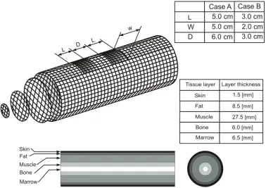
The geometry of the human upper arm is modeled by concentric cylinders for the skin (1.5mm), fat (8.5mm), muscle (27.5mm), cortical bone (6mm) and bone marrow layers (6.5mm) (Fig. 1). Each layer is described by the conductivity σ and also the relative permittivity ε. A large range of values for σ and ε at each layer have been published in literature [5-6]. The properties used in this report for different layers are show in Table 1 [5]. Dielectric permittivity was supposed to be independent of the frequency.
Specific conductivity
σ [S/m] permittivity Relative ε
Skin 0.00025 6000
Fat 0.03 25000
Muscle 1 100000
Bone 0.02 3000
Marrow 0.08 10000
Table 1. Tissue material constants [5]
Our interest consists in gaining information and knowledge about the electric field propagation through lower arm tissues under static hypothesis, as well as in dynamic conditions. We therefore use the full dynamics of the electrical propagation through tissues. This is a generalization of the common implementation of electrical stimulation modeling by static models, which neglect the eventual transient aspects of the electrical current and potentials with transient distributions in space. At higher frequencies, a satisfactory confining analysis cannot be achieved without considering the transient effects.
t
ρ ρ
∂
∇ = − ∇ = −
∂
J D (1)
, D=εE J=σE E, = −∇V (2)
0
V V
t
σ ε ∂
∇ ∇ + ∇ ∇ =
∂ (3)
where J is the electrical current density vector, ρ represents the electrical charge density (volume), D stands for dielectric displacement vector, E represents electrical field strength vector, V stands for electrical potential, ε is dielectric permittivity, and σ is electrical conductivity.
Fig. 1. Basic geometrical data for the human upper arm. The concentric cylinders denote different tissue layers: skin, fat, muscle, bone and bone marrow. Two cases A and B represent
different electrodes shape, size and position.
A standard Galerkin procedure is applied to Eq. 3 in order to derive the finite element equations [7]. The unsteady equations for finite element solver were obtained by modification of PAK-P software package, which is developed at University of Kragujevac [8].
We implemented different shapes and sizes of the electrodes into the finite element model, in order to compare the results with those available in the literature as well as with our own experimental observations.
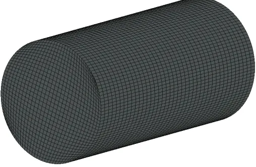
Fig. 2. Finite element mesh used for the electro-stimulation modeling, 60000 3D 8-node finite elements. Five different groups of material are associated with the tissue layers.
For the first case we used the 5cm square electrodes with distance of 6cm between them. We denote this model as the case A. A monopolar constant current pulse with pulse duration of 1000 μs and amplitude 9mA were applied in the case A. The current density J as an input flux is directly calculated from the given current amplitude and surface of the electrodes.
2.2 Experimental setup
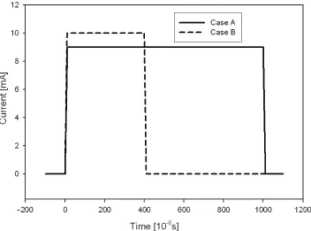
Fig. 3. Prescribed current pulses for Case A and Case B. The current for the Case A, I= 9 mA with periodic pulse duration 1000 μs; and for the Case B the current I=10 mA with periodic
pulse duration 400μs.
Fig. 4. Experimental setup for electrical stimulation. Two electrodes of size 2x3 cm are connected to a current regulated electric stimulator. The distance between electrodes is 3cm.
3. Results
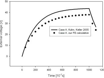
We first present the results for Case A which corresponds to modeling and experiment by Kuhn and Keller [5]. These authors analysed a transient FE model with tissue parameter from Table 1 and compared their measurements on three human volunteers. Our FE calculation of the voltage between two electrodes has shown very similar behavior in comparison to the results of these authors (Fig. 5). A small deviation from [5] could probably be because Kuhn and Keller used different conductivities in the longitudinal and transversal directions. Total electrical potential distribution for maximum voltage between two electrodes on the skin is shown in Fig. 6. As it is expected, the maximum voltage occurred at the end of input current pulse tp=1000μs. Also, both calculations demonstrate the strong influence of the transient conditions which is caused by the inertial effects of the voltage response on the skin as well as in the muscle and the nerves. This directly emphasize that permittivity plays an important role in the functional electrical stimulation.
Fig. 5. Voltage between the stimulation electrodes vs time for one pulse. Pulse duration tp=
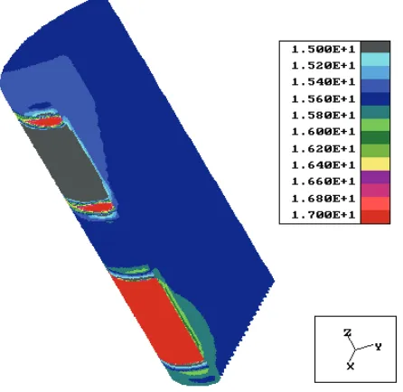
Fig. 6. Electrical potential distribution at the end of pulse in the Case A. The pulse duration tp=1000μs. The square of 5cm electrodes was used, with 6cm distance between electrodes.
The voltage distribution inside muscle and other tissue layers for the maximum pulse in the case A is shown in Fig. 7. These values are smaller than the voltage on the skin due to low skin conductivity. Velocity vector distribution of the electrical field for the same time step is shown in Fig. 8. As expected, the electrical field produces the flow from input to output electrode, caused by electrical potential difference at the electrodes.
Fig. 8. Electrical vector distribution inside the upper human arm at the end of pulse in the Case A. The pulse duration tp=1000μs.
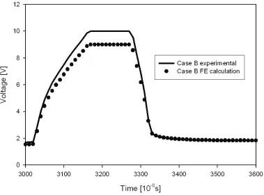
Fig. 9. Voltage between the stimulation electrodes vs. time; case B, experimental and computed values. The pulse duration tp= 400 μs, applied current amplitude I = 10 mA, two electrodes size
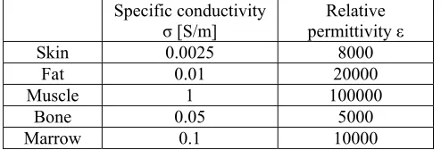
The result for the Case B for voltage distribution between electrodes vs time is shown in Fig. 9. For the finite element modeling we used the same geometrical data as in the Case A. The current amplitude I=10mA and pulse duration 400μs is used in the experiment. The voltage response measured on a few volunteers was averaged. Tissue properties fitted with the experimental results are given in Table 2. It was observed that the specific conductivity for the skin should be 10 times higher then in Case A. The reason for that could probably be due to use of a gel on the skin during experiment, which produces a much higher electrical conductivity for the wet skin in comparison with the Case A. The relative permittivity for all layers used in Case B was similar as used in Case A.
Specific conductivity
σ [S/m] permittivity Relative ε
Skin 0.0025 8000
Fat 0.01 20000
Muscle 1 100000
Bone 0.05 5000
Marrow 0.1 10000
Table 2. Tissue material constants fitted with our experimental setup.
3. Conclusions
A transient 3D finite element model is developed to simulate the functional electrical stimulation of the human upper arm over time. Our model was validated by comparison the computed results with the experimental measurements from literature [5] and our measurements. We analyzed two cases, A and B, with the same geometrical data but different input current amplitude, pulse duration, electrode size, positions and tissue properties. The case A was compared with experimental and numerical results in [5]. For the Case B we fitted tissue properties in order to obtain the results close to the experimental response measured on few volunteers. Both cases have shown a strong inertial effect due to a transient conditions and dominant relative permittivity of the skin. This observation suggests a possible change in the current therapeutic strategy and potential measurement during the functional electrical stimulation. Also, the dielectric tissue properties (permittivity) cannot be neglected and the static approach of electrical stimulation should be replaced by with the dynamic one. Future research should include verification of computer modeling by comparison experimental and numerical results inside the muscle as well as in the nerves.
Acknowledgements:
Support of Serbian Ministry of Science, Projects ТR – 6209 and OI– 144028.
References
[1] Sadiku, Mathew N.O., Numerical techniques in electromagnetics, CRC Press LCC, N.W. Corporate Blvd., Boca Raton, Florida, 2000.
[4] Malmivuo, J., Plonsey, R., Bioelectromagnetism, Oxford University Press, New York, 1995.
[5] Kuhn, A., Keller T, A 3D transient model for transcutaneous functional electrical stimulation, 10th Annual Conference of the International FES Society, 2005, Montreal,
Canada.
[6] Kuhn, A., Rauch, G.A., Panchaphon, B., Keller, T., Using transient FE models to assess anatomical influences on electrical stimulation, FEM Workshop, Ulm, vol. 12, 2005.
[7] Kojic M., Filipovic, N. Stojanovic, B. and Kojic N., Computer Modeling in Bioengenineering, Theoretical Background, Examples and Software, J. Wiley (in press).
[8] Kojic M., Filipovic N., Slavkovic R., Zivkovic M., Grujovic N., PAK-P Finite Element Program for Fluid Flow through Porous Medium, University of Kragujevac, 2001. [9] Peulic A, Filipovic N, Multifunctional electro-stimulator, Proc.51st ETRAN
![Table 1. Tissue material constants [5]](https://thumb-us.123doks.com/thumbv2/123dok_us/8369915.1674852/2.499.142.386.392.485/table-tissue-material-constants.webp)