Hardware/Software Co-design Approach for an
ADALINE Based Adaptive Control System
Shouling He
Department of Electrical and Computer Engineering, Penn State Erie, Erie, PA 16563 Email: sxh63@ psu.edu
Xuping Xu
Department of Electrical and Computer Engineering, Penn State Erie, Erie, PA 16563 Email: Xuping-Xu@ psu.edu
Abstract—In this paper, we report some results on hard-ware and softhard-ware co-design of an adaptive linear neuron (ADALINE) based control system. A discrete-time Pro-portional-Integral-Derivative (PID) controller is designed based on the mathematical model of the plant. The pa-rameters of the plant model are identified on-line by an ADALINE neural network. In order to efficiently and economically implement the designed control system, a Field Programmable Gate Array (FPGA) chip is em-ployed to process the measured data and generate control signals. Moreover, a microprocessor is exploited to per-form the core computation of the ADALINE algorithm. Throughout the paper, we design and test the control system for a permanent magnetic DC motor. Our ex-periment results demonstrate the effectiveness of the pro-posed approach. It is worth noting that the experimental bed in the present paper can also be used as a low-cost general prototype to satisfactorily test adaptive control systems, owing to the benefit of software and hardware co-design.
Index Terms — Hardware, software, ADALINE, FPGA, adaptive control.
I. INTRODUCTION
PID controllers have been widely used over the past five decades due to their simplicity, robustness, effec-tiveness, and applicability for a broad class of systems. Despite the numerous control design approaches that have appeared in the literature, it is estimated that nowadays PID controllers are still employed in more than 95% of industrial processes [1]. Likewise, adap-tive tuning of the parameters of PID controllers in nonlinear and time-varying systems has been of great interest to control engineers. With the introduction of on-line identification of process models and momen-tary tuning of PID gains, particularly with some state-of-the-art parameter predictive approaches, the compu-tational burden involved in the tuning becomes very heavy. Since a low-cost microcontroller with limited resources may not satisfy the requirements of many demanding applications, expensive and multifunctional microprocessors need to be used. Consequently, the
challenges of software management and energy con-sumption cannot be avoided in real-time control sys-tems.
On the other hand, with the rapid development of microelectronics, hardware design devices such as field programmable logic arrays (FPGAs) and complex pro-grammable logic devices (CPLDs) provide possibilities of fast and easy digital implementation of controllers in embedded systems. The strength of programmable logic devices is their high speed and parallel hardware implementation structures. Particularly, due to their digital nature, they can be conveniently processed in various digital manners. Furthermore, by varying the hardware configuration during operation time without changing the number of gates and the power demand, controllers based on such hardware devices can adapt to different operating conditions. Such a feature is par-ticularly useful for tolerance control with redundant function setups [2]. In view of these, such hardware technologies open the door for faster and more flexible control system design.
Albeit attractive, pure hardware implementation does not provide a complete solution to system design. Due to the lack of common mathematical function li-braries for those hardware devices, control and system parameter identification algorithm have to be imple-mented in time consuming and expensive processes. Moreover, some identification and control algorithms may be better implemented serially in software. In this regard, we note that successful design of a practical control system should be characterized by the follow-ing: a fully developed adaptable and robust algorithm, efficient hardware design combined with flexible soft-ware structure.
neural network. Second, in terms of implementation, an FPGA is used to receive and filter the digital signals measured by a sensor. The processed digital signals are sent to a microcontroller via the parallel port. In the microcontroller, an ADALINE neural network is used to estimate the plant parameters and a control signal is produced based on the estimation. The values of the generated control signal will be transferred into the corresponding Pulse-Width-Modulation (PWM) signal in the FPGA chip and sent to an actuator for the control purpose. To clearly demonstrate our hardware and software co-design approach and show its effective-ness, we design and implement a controller for a per-manent magnetic DC motor throughout the paper.
The present paper is organized as follows. In Section II, we review some previous works on PID control sys-tem designs using FPGAs co-implemented with micro-processors. Then, the plant model, the controller design as well as the ADALINE algorithm are briefly intro-duced. Software simulation results are also given for the purpose of comparison. In Section III, the hardware implementation architecture for real-time control appli-cations is presented. Experimental results are shown in Section IV and the advantages of hardware and soft-ware co-design approach are discussed in Section V. Finally, Section VI summarizes our research work.
II. PLANT MODELING AND CONTROLLER DESIGN
A. Previous work
Adaptive PID control systems were initially pro-posed by Åström in the early 1980s [3]. Since then, considerable work has been done on the adaptive tun-ing of gains and related parameters of PID controllers. Roughly speaking, the approaches to self-tuning of PID controller gains can be classified into two categories --model-based tuning [4] and knowledge-based tuning [5][6]. Normally, these approaches require the knowl-edge of either the plant models or the plant behaviors. For example, in [6], a fuzzy logic controller was de-signed based on a plant model obtained by using a neu-ral network. In such a case, the convergence of a multi-layer neural network to the plant model becomes a critical issue when the environment parameters, such as frictions, temperature and pressures, are subject to con-tinuous changes.
In the sequel, we will use an ADALINE neural net-work to identify the plant model. The ADALINE neu-ral network has been proved to converge to a desired model as long as the learning rate is properly selected [7]. Numerous application examples [8][9] have shown that the algorithm can converge fast and does not need additional information or knowledge from the identi-fied object. Furthermore, the algorithm can guarantee the cost function such as the mean square errors has no local minima in controller parameters space. When the FPGA technique is employed for the hardware and software co-design, the high-speed and parallel imple-mentation can make the signal sampling period small
enough so that the ADALINE neural network model can quickly adapt to the parameter change of a highly nonlinear and constantly varying plant.
As far as implementing PID controllers using FPGA chips is concerned, we noticed that fixed-gains PID controllers have been tested in the papers [10][11]. However, to our best knowledge, adaptively tuned PID controllers implemented using FPGAs have not been studied before.
B. Mathematical model of a DC motor
To better illustrate our hardware/software co-design approach, in the rest of the paper we will primarily fo-cus on the controller design for a permanent magnetic DC motor. The dynamical model of the DC motor is given by the following circuit and mechanical equations [12],
ș
K i R dt di L
v a a b
a a
a (1)
) sign( m
m
m I ș b ș a ș
T u (2)
where the parameters and variables are defined as in Table I.
TABLE I. MOTOR PARAMETERS va applied armature voltage (volts)
La armature inductance (H)
ia armature current (amp)
Ra armature resistance (ohm)
Kb back emf constant (voltusecond/rad)
T motor shaft angle (rad) Tm output torque (Num2
)
Im the moment of inertia of motor & load (Kgum2)
bm viscous friction coefficient (Numusecond/rad)
a static friction coefficient (Num)
The output torque Tmof the motor is proportional to the armature current ia, i.e. Tm = Kt ia. By omitting the static friction, we can derive the following transfer function from (1) and (2),
m a t b m a m a 2 m a
t
a() ( )
) ( ) G(
b R K K s b L I R s I L
K s
v s
ș
s
(3)
Here we regard the applied armature voltage vaas the input and the angular velocity ș of the motor shaft as the output. Now if we assumeLaIm |0 and define
) /(
)
( b t a m a m a m 0 K K R b R I L b
Ȧ and
) /( b t a m t K K Rb K
K , we can simply write (3) as
0 0 ) G(
Ȧ
s KȦ
s
(4)
C. PID controller design
DC motor. In the discrete-time domain, the transfer function of a PID controller is
c p d i
1 1 ) ( G K z z K z z K z
. (5)
In our setting, an optical encoder is used to measure the angular position of the motor and an FPGA chip is employed to process the number of counts within a sampling period of the control algorithm. Since a trans-formation is needed to convert the angular velocity of the motor to the number of counts during the sampling period, a feedback gain,
f )
H(s K , (6)
is included in the feedback path.
The resultant closed-loop control system is shown in Figure 1.
Figure 1. Closed-loop Control System
For the zero-order hold sampling of the motor plant which works in the continuous-time domain, the sam-pled plant model is described by its pulse-transfer op-erator (see [13]),
1 1 1 1 1 ) G( a z z b
z , (7)
where 1 T
0 Z
e
a , 1 (1 T)
0 Z
e K
b , and T is the sam-pling period. Since the parameters of the motor vary with time and nonlinearities, such as static friction, are not considered in the model (4), the parameters a1 and b1 need to be updated on-line. Combining (4), (5) and (7), to determine the poles for the closed-loop system in Figure 1, we only need to consider the roots of
0 ) ( ) ( ) (
1Gc z G z H z
i.e., the roots of
0 ) ( ) 1 )( 1
( f 1 1 2
1 1
1
a z z K b a bz cz (8)
where a KpKiKd,b Kp 2Kd,c Kd.
From (8), it is clear that the closed-loop poles are the roots of 0 ) ( ) 1
( 1 f
1 1 f 1 2 1 f 1 3
abK a z bbK a z cbK
z (9)
We expect the poles of the discrete-time closed-loop system in Figure 1 to be within the unit circle so that the system is stable [13]. In this application, we choose
the desired poles as -0.1, -0.1, and 0.5. From (9), we have . 005 . 0 , 09 . 0 ) ( , 3 . 0 ) 1 ( f 1 1 f 1 1 f 1 K cb a K bb a K ab (10)
In view of (10), the PID controller gains can be writ-ten as functions of the motor plant parame-tersKf,a1,b1. They are
) /( 005 . 0 ) /( 605 . 0 ) /( ) 1 . 0 ( f 1 d f 1 i f 1 1 p K b K K b K K b a K (11)
Based on the encoder’s performance, i.e. the number of counts per revolution, and the sampling period, the gain Kfcan be decided. However, as mentioned before, the parametersa1andb1 may vary with time. Hence, an ADALINE network is used to estimate them.
D. ADALINE based parameter identifier
Adaptive linear neuron technique was first intro-duced by Widrow and Hoff [14]. It has been widely used in the area of signal processing. Here we apply it to the parameter identification of the plant.
Without loss of generality, we use the following lin-ear neuron model for (7),
) ( ) ( )
(k wk p k
y , (12)
wherey(k) ș(k), T
] ) 1 ( ) 1 ( ș [ )
(k k u k
p and
)] ( ) ( [ )
(k a1 k b1 k
w .
For each measured angular velocity of the motor at the sampling instant tk kT , the weights of the
ADALINE network are updated,
) ( ) ( ) 1
(k wk wk
w Dk' , (13)
so that the squared error between the estimated value from (12), y(k), and the measured data, ym(k),
2
m( ) ( ))
( )
(k y k y k
E (14)
is minimal.
We select the learning rate, Dk, by minimizing the
cost function (14) with respect to Dk at each iteration
[7]. From (12), (13) and (14), we have
). ( | ) ( ) ( 2 1 | ) ( ) ( ) 1 ( T 2 T 2 2 T k w w E k w w E k w k E k E k k k k ' ' D ' D w w w w (15)
The derivative of (15) with respect to Dk for the cost
function (14) can be shown to be
) ( | ) ( ) ( | ) ( T 2 T 2
T w k
If we set (16) equal to zero and solve for Dk, we have
) ( ) ) ( / )( (
) / )( (
T 2 T 2
T
k w w E k w
w E k w k
' '
' D
w w
w w
(17)
Using the steepest decent method, 'w(k)in (13) is chosen as the gradient of the cost function with respect to the weights,(wE/ww). Then, (17) will be
) / )( ) ( / )( / (
) / )( / (
T 2
T 2
T
w E w E w E
w E w E k
w w w
w w w
w w w w
D . (18)
By inserting (12) into (14), then the gradients of the cost function with respect to the weight vector w and Hessian matrices can be derived as
| 2 ( ) ( )
) ( ), ( 2
| T
2 T 2
T p k p k
w E k
Ep w
E
k k
w w
w w
(19)
By combining (18) and (19), and considering also'w(k) wE/ww(k), we have the updated weight vectors as
) ( ) (
) ( | ) ( ) 1
( T
T
k p k p
k p E k w k
w k (20)
In order to prevent the values of the vector p(t) from being too small so that the updated value becomes too large, a parameter E is added to (20),
) ( ) (
) ( |
) ( ) 1
( T
T
k p k p
k p E
k w k
w k
E (21)
The weights of the ADALINE network is updated in the following way: at each sampling instant, when the angular velocity, șm(k), of the motor is measured, the squared error E of (14) is calculated. The weight vec-tors in (21) will correspondingly be updated. Using the updated weight vectors and input vector, the angular velocity of the DC motor in next sampling instant can be estimated using (12).
Compared to the recursive least-squares estimator, the ADALINE algorithm eliminates the recursion of the covariance matrix of the estimates. Since the ADALINE algorithm doesn’t need to wait the covari-ance matrix converge when the measurements change significantly, it is more flexible to adapt to a new envi-ronment. Furthermore, it reduces the computational load caused by updating the covariance matrix.
E. Simulation results
Software simulation for the adaptive control of the permanent magnetic DC motor has been conducted using the MATLAB toolbox. The parameters a1 and b1 were regarded as unknown parameters for identifica-tion. The PID controller parameters Kp,Ki, and Kd are obtained using (11).
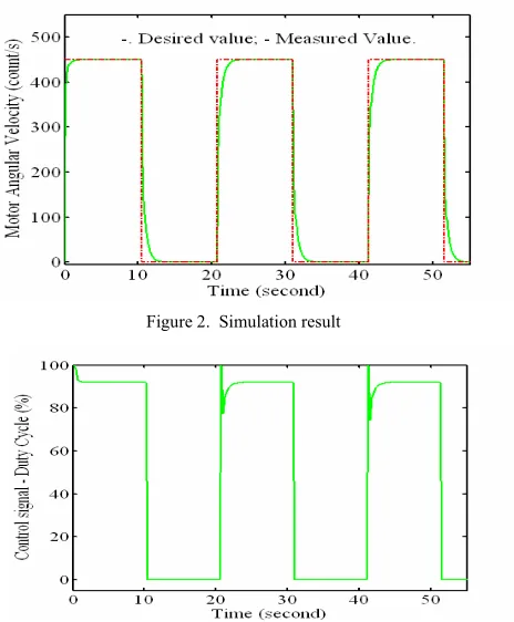
The desired angular velocity of the DC motor was switched between 0RPM and 420RPM every 10 sec-onds. In addition, we assume the encoder can generate 64 pulses when the motor turns one revolution. Then,
with 64 counts per 2S radians, we have the gain in the feedback path is 64/2S|10.2 count/rad. Furthermore, the angular velocity of the motor will be represented in the number of counts per second. For the angular ve-locity of 420RPM, the number of counts per second is 420u64/60=450. When the motor runs, the encoder will count the number of pulses. The control system samples the number of pulses and generates a control signal every 250 milliseconds.
The parameters of the motor model are assumed as follows. The equivalent time constant is 200 millisec-onds. The gain from the voltage input to the angular velocity of the motor is 3.5 rad/second/volt. Both val-ues are derived from the motor’s data sheet and cali-brated by the measurement results. The initial weights for the adaptive ADALINE neural network were taken as [w1w2] = [0 1].
Simulation results of the angular velocity and the pertaining control signal are shown in Figures 2 and 3. From these figures, we can see that (1) The ADALINE algorithm can identify the model parameters within a short time. It takes about 2 seconds before the output response follows the desired trajectory. (See Figure 3, from t=0 second to t=2 second.) (2) We choose the poles of the closed-loop system to be at -0.1, -0.1, 0.5. When the switched input signal is changed from 0 to 450 count/second, the effect of the non-dominant poles, -0.1, can be clearly seen at the transient phase. The output response is fast. However, as time proceeds, the effect of the dominant pole z=0.5 becomes more pro-nounced and the system response becomes slower. (See Figure 2, the response of the motor angular velocity versus the time from 21 second to 23 second.)
Figure 2. Simulation result
Figure 5. Illustration of logic filter design
III. HARDWARE/SOFTWARE CO-DESIGN IMPLEMENTATION
The ADALINE based adaptive control algorithm was implemented mainly by the following hardware: a SPARTAN II FPGA chip from Xilinx, Inc [15] and the PIC18F452 microcontroller from Microchip Technol-ogy, Inc [16]. The hardware design was implemented using the Xilinx Integrated Service Environment (ISE) via VHSIC hardware description language (VHDL) and schematic diagrams.
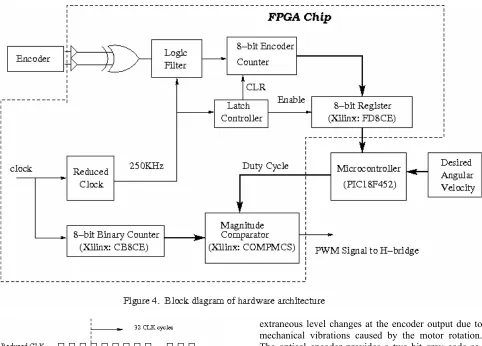
Figure 4 shows the block diagram of top level hard-ware and softhard-ware co-design implementation. Except for the ADALINE algorithm and the adaptive PID con-trol algorithm which are implemented in the PIC18F452 microcontroller, all other functions are designed in a hardware approach and implemented on the SPARTAN II chip. In the following paragraphs, we detail these functions.
A. Logic filter design
The logic filter is constructed for the elimination of
extraneous level changes at the encoder output due to mechanical vibrations caused by the motor rotation. The optical encoder provides a two-bit gray code se-quence. Using an XOR gate, we can obtain the pulses as double of the original counts provided by the optical encoder.
As shown in Figure 5, instead of directly counting the pulses from the encoder, a clock of 250 KHz was used here. When the clock cycle is at the positive edge, the input from the encoder to the FPGA is checked and recorded. The recording action will repeat through 32 consecutive clock cycles. Among the 32 recorded data, If the number of ones is larger than the number of zeros, the output of the logic filter is one. Otherwise, the value of zero will be asserted. (Notice that the logic filter will incur a time delay of 32/250KHz|0.1 microsecond. If a shorter delay is required, a higher frequency clock can be applied.)
B. Sampling angular position of the motor
An 8-bit register with clock enable and asynchro-nous reset is used to capture the output of the 8-bit en-coder counter. The desired capture period is controlled by a latch controller. It counts the number of the re-duced clock cycles from 0 to 62495 (250KHz/4Hz-5=62495). Then the latch controller sends an enable signal to the 8-bit register connected to it. The register latches the number of counts sent by the encoder counter within two following clock cycles. After that, two more clock cycles are used to clear the encoder counter. Finally, the latch controller will be reset to repeat the above process.
implemen-tation, since the sampling period for the adaptive PID controller is 250 microseconds (4Hz), the angular ve-locity of the motor is obtained by four times the output of the 8-bit register.
C. Generation of PWM signal
The PWM signal is generated when a duty cycle value is sent by the PIC18F452 microcontroller to the FPGA chip. The master clock provided by the FPGA chip drives an 8-bit binary counter. Since the binary counter rolls over to zero after counting 256 pulses, the output of the counter provides a time-base period. For the clock of 100 MHz, the time period for the binary counter to roll over is 2.56 microseconds. (The fre-quency is 390KHz.) While the binary counter accumu-lates counts from 0 to 255, the magnitude comparator checks the value of the duty cycle (sent by the micro-controller) with it. If the duty cycle value is larger than the number of counts, the output is one. Otherwise, the output is zero. Thus, the output of the magnitude com-parator is the desired PWM signal.
When the measured angular velocity of the motor is sent to the PIC18F452 microcontroller through a paral-lel port, the ADALINE algorithm (12), (14) and (21) is executed and the weights of the ADALINE network is updated. Furthermore, a control signal is calculated based on the estimated parameters.
To implement the PID algorithm, we used the in-cremental algorithm proposed in [17]. A PID controller in the discrete-time domain can be written as
( ) ( ) ( ) d( ( ) ( 1))
0 i
pek K
¦
e j K ek ekK k u
k
j
(22)
where e(k) is the error signal between the desired angu-lar velocity of the DC motor and the measured signal from the encoder. The control signal can also be repre-sented by a correction signal term 'u(k) plus the con-trol signal at the previous sampling step k-1,
)) 2 ( ) 1 ( ( ) ( )
1 ( ) 1
( d
1
0 i
p
¦
k e k e K j e K k e K k u
k
j
(23)
By subtracting (23) from (22), we have
)) 2 ( ) 1 ( 2 ) ( (
) ( )) 1 ( ) ( (
) 1 ( ) ( ) (
d
i p
k e k e k e K
k e K k
e k e K
k u k u k u
'
K0e(k)K1ek1)K2e(k2) (24)
where
d 2
d p 1
d i p 0
2
K K
K K K
K K K K
Thus, the current control output is
) 2 ( ) 1 ( ) ( ) 1 ( )
(k u k K0ek K1e k K2e k
u (25)
The incremental algorithm (25) can avoid the accu-mulation of all past errors and therefore realize smooth status transition since the current control signal is based the last control signal and the correction signal.
With the above algorithm, at each sampling instant, after the weights of the ADALINE network is updated, the PID gains Kp, Ki and Kd will be calculated using
(11). Finally, (24) and (25) will be employed to achieve the current control signal. The control signal is the voltage signal required to drive the DC motor at a de-sired angular velocity. Based on the ratio between the voltage signal and its corresponding duty cycle value, the duty cycle signal can be obtained. For implementa-tion, the range of the duty cycle value is chosen from 0 to 255, i.e. the PWM signal has 8-bit resolution.
IV. EXPERIMENT
A permanent magnetic DC motor is used in the ex-periment. The armature inductance and resistor are 0.002H and 25ȍ, respectively. As discussed in Section III, the encoder counter and the corresponding digital filter as well as the PWM module are designed and downloaded onto the SPARTAN II FPGA chip. And the ADALINE network and control algorithm are com-puted in the PIC18F452 microcontroller. In addition to the hardware, the remaining components to implement the closed-loop control system includes (a) A power amplifier to amplify the voltage required by the DC motor. The value of the voltage is controlled by the PWM module. In this respect, we use the SN754410 quadruple half-H driver to adjust the voltage from 5volts to 12volts. (b) An encoder to provide the meas-urement of the angular velocity of the DC motor. The HRPG series optical encoder from Agilent Technolo-gies was incorporated into the hardware architecture. The encoder provides 32-pulse TTL compatible digital signal. By XORing two output channels signals, we can obtain 64 pulses per revolution.
All experiments were performed using the XSA-200 board V1.3 from XESS Corporation [18]. The board contains a 200-Kgate Xilinx Spartan-II as a main re-pository of programmable logic; a Xilinx XC9500XL CPLD used to manage the configuration of the FPGA to communicate with a host computer; a 256Mbit SDRAM for volatile data storage and 100MHz oscilla-tor as a on-chip master clock. The configuration bit-stream can be downloaded via parallel port using the GXSLOAD facility.
II, (the percentage of resource used over each of total resources is shown in parenthesis.) Notice that the im-plementation consumes very few resources.
Table II. HARDWARE RESOURCE USAGE
Slice LUT Flip-Flop Bonded IOBs Clock
79(3%) 77(2%) 77(1%) 31(17%) 100MHz
The PIC18F452 microcontroller, which has 16-bit in-structions and an 8-bit data path, was configured with a 10MHz oscillator and parallel inputs and outputs. The designed ADALINE algorithm and PID controller were written in the Embedded C code under MPLAD IDE environment and compiled by CCS C compiler from CCS Inc. The generated machine code was downloaded to the PIC18F452 chip via the hyper ter-minal on Windows operating system, the RS232 serial port and MAX232 signal conversion chip. After com-piling the source code, the generated machine code uses 5.2Kbyte flash memory and 1.5Kbyte RAM. Compared to the microcontroller’s resources, i.e. 32K byte flash memory and 1.5K byte RAM, we still have room to modify the adaptive control algorithm. For the program provided in Section III, it took about 10 milli-seconds to complete the computation.
For the experiment, the initial parameters for the weights were still chosen as w = [0 1]; the desired tra-jectory switched between 0RPM and 420RPM with a time period of 10.06632 seconds. The Timer1 rollover interrupt feature provided by the PIC18F452 microcon-troller is used to generate the squared waveform.
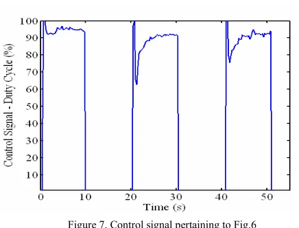
Figures 6 and 7 show the experimental results. The results provide us some information that can not be obtained from a pure software simulation. First, the response of the motor angular velocity has a larger undershoot at the first two seconds. This indicates the initial values of weights in the ADALINE algorithm may be far from the real parameters of the DC motor. However, the algorithm can make the weights con-verge quickly to the real parameters. Second, the out-put response of the angular velocity for the real-world test is faster than that in software simulation. (See Fig-ure 6, the time between 21 second and 23 second.) This can be contributed by the nonlinearities of the motor system which were not included in the mathematical model. Third, the measurement noise can be observed from the measured data. The observation suggests the hardware simulation test bed constructed by the FPGA chip and the microcontroller can be an ideal facility for us to check whether a developed adaptive control algo-rithm is sensitive to the imperfection of sensors and furthermore a proper sensor can be chosen for the con-trol algorithm. Forth, the effect of the dominant pole is more obvious in hardware implementation than that in pure software simulation. Figure 3 shows the control signal oscillates 20% over the final steady value when the output of the angular velocity at the transient phase. However, in Figure 7, the control signal varies in the
range of 35% around the final steady value when the set point is switched from 0 to 450 counts per second.
Overall, even though the accuracy of the encoder is low, yet there is little fluctuation of the output when the angular velocity of the motor follows the desired trajectory, the ADALINE based adaptive controller works satisfactorily.
V. ADVANTAGES OF HARDWARE AND SOFTWARE CO -DESIGN
Compare to traditional control system designs, the hardware and software co-design implementation ap-proach enjoys the following advantages: (1) Because the FPGA chip is used to process the measured signal from a sensor and generate the PWM signal, the micro-controller is released from handling unexpected inter-rupts due to the CCP module capturing signals and calculating PWM signals. Instead, it can focus on com-plicated algorithm for signal processing and control signal synthesis. The resultant software management and timing programming are easy to be dealt with. (2) The approach helps saving some resources of the mi-crocontroller. For example, a multi-channel encoder may require multi-channel capturers or accumulators in a microcontroller to capture the pulse inputs. Thus, the cost for the microcontrollers with more resources will be more expensive. In our co-design implementation, only parallel ports of the microcontroller were em-ployed to transfer data between the microcontroller and the FPGA chip. Most required functions are imple-mented using the FPGA chip via a hardware approach. Furthermore, in terms of hardware design, the hard-ware description language and the FPGA chips provide convenient tools to construct extra desirable features for a project, for example, creating multi-channel input signal capturers or multi-channel PMW signal genera-tors, etc. (3) Programming with a microcontroller frees one from trivial and low-level floating-point computa-tion on an FPGA chip, which has been proved to be less efficient and more time consuming. In particular, for control algorithms that are highly dependent on floating-point arithmetic to guarantee the accuracy or require serial signal processing, using a microprocessor as an IP core in a system is a reasonable tradeoff be-tween design time and design cost.
VI. CONCLUSIONS
Figure 6. Motor angular velocity response versus time
Figure 7. Control signal pertaining to Fig.6
Performance tests using our hardware and software co-implementation approach shows that the simple platform can be an ideal environment to test advanced control system designs. Comparing to using microcon-troller or FPGA alone, the blend of microconmicrocon-troller and FPGA as proposed in this paper reduces the amount of resources for either the microcontroller or the FPGA chip. Moreover, it can be used to test very high speed control systems due to the extraordinary parallel com-puting performance provided by the FPGA chip.
REFERENCES
[1] K.J. Åström and T. H. Hagglund, “New Tuning Meth-ods far PID Controllers.” Proc. of 3rd European Confer-ence, pp. 2456-2462, 1995.
[2] A. DeHon and J. Wawrzynek, “Reconfigurable comput-ing: what, why, and implications for design automa-tion.” Proc. of the 36’ ACM/EEE conf. on Design Automation Conference, NewOrleans, Louisiana, USA, 1999, pp. 610 - 615.
[3] K.J. Åström and T. H. Hagglund, “Automatic tuning of simple regulators for phase and amplitude margin speci-fications”, Proc. of the IFAC workshop on Adaptive Systems in Control and Signal Processing, 1983. [4] K.J. Åström, “Automatic tuning and adaptation for PID
Controllers – A survey,” Control Eng. Practice, vol.1, no. 4, pp. 699-714, 1993.
[5] T. Ravichandran and F. Karray, “Knowledge based ap-proach for online self-tuning of PID-control,” Proc. of ACC, Arlington, VA, June 25-27, 2001.
[6] F. Karray, W. Gueaieb and S. Al-Sharhan, “The hierar-chical expert tuning of PID controller using tools of soft computing,” IEEE Trans. on Systems, Man and Cyber-netics-Part B: Cybernetics, vol. 32, no. 1, Feb. 2002. [7] M.T. Hagan, H.B.Demuth and M.H. Beale, Neural
Net-work Design, University of Colorado at Boulder, 1996. [8] Ki-hwan Eom and Seong-ho Kang, “Leanring method of
the ADALINE using the fuzzy logic system”, Neural Comput & Applic, vol. 14, pp. 235-242, 2005.
[9] R. EI Shatshat, M. Kazerani and M.M.A. Salama, “Multi converter appeoach to active power filtering us-ing current source converters”, IEEE Trans. on Power Dlivery, vol 16, Jan. 2001, pp. 38-45.
[10] L. Samet, N. Masmoudi, M.W. Kharat, and L. Kamoun, “A digital PID controller for real time and multi loop control: a comparative study,” Proc. of 1998 IEEE Int. Conf. on Electronics, Circuits and Systems, vol.1, Sept. 7-10, 1998, pp. 291-296.
[11] W. Zhao, B.H. Kim, A. C. Larson and R. M. Voyles, “FPGA implementation of closed-loop control system for small-scale robot,” Proc. of the 2005 Int. Conf. on Advanced Robotics, v. 1, pp.70-77.
[12] P. Kachroo and P. Mellodge, Mobile Robotic Car De-sign, McGraw-Hill, New York, 2005.
[13] K. J. Åström and B. Wittenmark, Computer-Controlled Systems, 3rd edition, Prentice Hall, 1997.
[14] B. Widrow and S. D. Stearns, Adaptive Signal Processing, Prentice-Hall, 1985.
[15] Xilinx Inc., Spartan-II 2.5V FPGA Family Product Specification, 2004, http://www.xilinx.com.
[16] Microchip Technology, Inc, PIC18FXX2 Data Sheet, 2003. http://www.microchip.com
[17] R. Isermann, Digital Control Design, Springer-Verlag, 1989.
[18] Xess Corporation, XSA-200 Board V1.3, User Manual, 2005, http://www.xess.com.
Shouling He received her Ph.D. degree in electrical engi-neering from the University of Erlangen-Nuremberg, Ger-many, in 2001. Since 2002, she has been an assistant profes-sor in the Department of Electrical, Computer and Software Engineering at Penn State Erie, Erie, PA. Her current re-search interests include hardware and software co-design for real-time control system; neural networks, nonlinear system analysis, modeling and simulation.
Xuping Xu was born in Shanghai, China, in 1974. He re-ceived the B.S. degrees in electrical engineering and applied mathematics from Shanghai Jiao Tong University, Shanghai, China, in 1995. He received the M.S. degrees in electrical engineering and applied mathematics, and the Ph.D. degree in electrical engineering from the University of Notre Dame, Notre Dame, IN, in 1998, 1999, and 2001, respectively.