(DOI: 10.24874/jsscm.2018.12.02.09)
Development of the Meshless Local Petrov-Galerkin Method to Analyze
Three-Dimensional Transient Incompressible Laminar Fluid Flow
M. J. Mahmoodabadi*, F. Mahmoodabadi, M. Atashafrooz
Department of Mechanical Engineering, Sirjan University of Technology, Sirjan, Iran E-mails: [email protected]
*corresponding author
Abstract
In this paper, a numerical algorithm is presented to simulate the three-dimensional transient incompressible flow using a meshless local Petrov-Galerkin (MLPG) method. In the proposed algorithm, the forward finite difference (FFD) and MLPG methods are employed for discretization of time derivatives and solving the Poisson equation of the pressure, respectively. The moving least-square (MLS) approximation is considered for interpolation, while the Gaussian weight function is used as a test function. Furthermore, the penalty approach is applied to satisfy the boundary conditions. Moreover, in two examples, the accuracy and efficiency of this approach is compared with the exact solutions.
Keywords: Meshless Local Petrov-Galerkin; Forward finite difference; Moving least Squares;
Gaussian weight function; Three-dimensional laminar flow; Transient incompressible flow.
1. Introduction
In the last few decades, a number of numerical techniques have been presented to solve the Navier-Stokes equations and for simulation of fluid flow. The computational fluid dynamics (CFD) techniques consisting of the finite difference, the finite element and the finite volume methods have achieved a lot of success in computer modeling of fluid flows. However, there are some drawbacks in these methods. For example, the mesh generation stage for these techniques is a far more time-consuming and expensive task, especially in three-dimensional problems or for those with moving boundaries. Therefore, it is necessary to find appropriate methods to overcome the difficulties associated with the mesh generation.
heat transfer (Sladek et al. 2004; Baradaran and Mahmoodabadi 2009; Baradaran and Mahmoodabadi 2010; Mahmoodabadi et al. 2011; Karagiannakis et al. 2016; Li et al. 2018), vibrations (Andreaus et al. 2005; Gu and Liu 2001; Gu and Liu 2001a; Rashidi Moghaddam and Baradaran 2017), plate and shell (Sladek et al. 2007; Li et al. 2008; Sladek et al. 2013; Vaghefi et al. 2016), convection-diffusion (Chen et al. 2018), Klein–Gordon equation (Darani 2017), electric-field integral equation (Honarbakhsh 2017), metal removal in laser drilling (Abidouab et al. 2018) and fluid flow (Arefmanesh et al. 2010; Najafi et al. 2012).
On the other hand, some researchers have tried to analyze and solve the fluid flow problems. For instance, Lin and Atluri used the MLPG method to solve incompressible Navier-Stokes equations for stokes flow and lid driven cavity flow problems (Lin and Atluri 2001). The application of the MLPG approach to simulation of incompressible flow was presented in Wu et al (2005). In that study, the MLPG formulation with some modifications was used for an irregular domain with scattered nodal distribution.Arefmanesh et al. employed the MLPG method with the unity weighting function to solve the Navier–Stokes and energy equations for non-isothermal fluid flow based on the stream function and vorticity formulation (Arefmanesh et al. 2008). A stabilized MLPG method for steady state incompressible flow was studied in (Wu et al. 2010). In that work, the streamline upwind Petrov–Galerkin method was used to overcome oscillations in convection-dominated problems. Mohammadi (2008) presented a new type of upwind scheme to stable the convection operator in the streamline. Avila et al. (2011) developed a novel MLPG-mixed finite volume method to analyze the steady state stokesian equations (Avila et al. 2011). Simulation of two-dimensional unsteady incompressible flow is done by the MLPG method and with a forward difference scheme for the time derivatives in Sataprahm and Luadsong (2014). In one of the latest researches, Enjilela and Arefmanesh proposed a stabilized two-step Taylor-characteristic-based MLPG method to solve laminar fluid flow and heat transfer problems (Enjilela and Arefmanesh 2015). The results of that work shown that very good agreements exist between the results obtained using the proposed meshless method with those obtained using the conventional methods.
Although there are some studies about the simulation of laminar fluid flow using the meshless methods, to the best of the author’s knowledge, the analysis of three-dimensional transient incompressible fluid flow problems using the MLPG approach is still not studied. This motivates the present study for extension of the MLPG formulation to solve the three-dimensional transient incompressible Navier-Stokes equations in the primitive variables form. More precisely, in order to solve the Poisson equation of the pressure in the three-dimensional domain, the MLPG method is employed and combined with the FFD technique.
The rest of the paper is organized as follows. Section 2 presents the problem formulation and Discretization of time derivatives and the algorithm. In Section 3, details of MLPG formulation and local weak forms, moving least squares (MLS) approximation and the considered weight function are described. Section 4 illustrates the numerical examples and the related validations. Finally, Section 5 concludes the paper.
2. Problem and analysis algorithm
2.1 Problem formulation
= + + − − − − +
2 2 2
2 2 2
1
( ) u
Re x
u u u u u u u p
v w f
t x y z x y z x (1)
= + + − − − − +
2 2 2
2 2 2
1
( ) u
Re y
v v v v v v v p
v w f
t x y z x y z y (2)
= + + − − − − +
2 2 2
2 2 2
1
( ) u
Re z
w w w w w w w p
v w f
t x y z x y z z (3)
+ + =
0
u v w
x y z (4)
where u, v and
w
are the velocities inx
, y andz
direction, respectively. p shows thepressure,
f
x, fy andf
z are the body force. Re represents the Reynolds number. Equations (1)to (3) are the momentum equation and Equation (4) is the continuity equation. The boundary conditions can be assumed to be:
= = = = u
u u
v v
w w
p p
on
(5)where u and Γ𝑞 are subset of which satisfy u = q .
2.2 Discretization of time derivatives and the algorithm
To deal with the time derivatives, a time stepping method based on the following approximations is employed.
+
−
1(x) (x)
(x,t )
n n
n
u u u
t t (6)
+ − 1 (x) (x) (x,t ) n n n
v v v
t t (7)
+
−
1(x) (x)
(x,t )
n n
n
w w w
t t (8)
where x=(x,y,z) ,T un =u(x,tn), vn =v(x,tn), wn =w(x,tn) and ∆𝑡 is the time step. For discretizing Equations (1) to (3) at times level n, the following substitutions are regarded.
+ −
= + + − − − − +
1 2 2 2
2 2 2
1 u u u
( ) u
Re
n n n n n n n n n
n x
u u u u u p
v w f
t x y z x y z x (9)
+ = − + + + − − − +
2 2 2
1
2 2 2
1 u u u
[ ( ) u ]
Re
n n n n n n n
n n n
x
p u u u
u u t t v w f
x x y z x y z (10)
let,
= + + + − − − +
2 2 2
2 2 2
1 u u u
[ ( ) u ]
Re
n n n n n n
n n n
x
u u u
F u t v w f
x y z
therefore,
+ = −
1 n
n n p
u F t
x (12)
and
+ −
= + + − − − − +
1 2 2 2
2 2 2
1
( ) u
Re
n n n n n n n n n
n y
v v v v v v v v p
v w f
t x y z x y z y (13)
+ = − + + + − − − +
2 2 2
1
2 2 2
1
[ ( ) u ]
Re
n n n n n n n
n n n
y
p v v v v v v
v v t t v w f
y x y z x y z (14)
let
= + + + − − − +
2 2 2
2 2 2
1
[ ( ) u ]
Re
n n n n n n
n n n
y
v v v v v v
G v t v w f
x y z
x y z (15)
therefore
+ = −
1 n
n n
p
v
G
t
y
(16)and
+ −
= + + − − − − +
1 2 2 2
2 2 2
1
( ) u
Re
n n n n n n n n n
n z
w w w w w w w w p
v w f
t x y z x y z z (17)
+ = − + + + − − − +
2 2 2
1
2 2 2
1
[ ( ) u ]
Re
n n n n n n n
n n n
z
p w w w w w w
w w t t v w f
z x y z x y z
(18) let = + + + − − − +
2 2 2
2 2 2
1
[ ( ) u ]
Re
n n n n n n
n n n
z
w w w w w w
L w t v w f
x y z
x y z (19)
therefore
+ = −
1 n
n n p
w L t
z (20)
Using Equations (12), (16) and (20), the following relations are obtained.
+
= −
1 2
2
n n n
u
F
p
t
x
x
x
(21)+
= −
1 2
2
n n n
v G p
t
+
= −
1 2
2
n n n
w
L
p
t
z
z
z
(23)Substitution Equations (21 to (23) into Equation (4), yields Equations (24) and (25).
+ + +
+ + =
1 1 1
0
n n n
u
v
w
x
y
z
(24)and
+ + = + +
2 2 2
2 2 2
1
( )
n n n n n n
p p p F G L
t x y z
x y z (25)
Equation (25) is the poisons equation with the non-zero source term. The numerical implementation of the procedure described from Equations (12) through (25) can summarized as follows:
1. Compute the intermediate velocity field using
= + + + − − − +
2 2 2
2 2 2
1 u u u
[ ( ) u ]
Re
n n n n n n
n n n
x
u u u
F u t v w f
x y z
x y z (26)
= + + + − − − +
2 2 2
2 2 2
1
[ ( ) u ]
Re
n n n n n n
n n n
y
v v v v v v
G v t v w f
x y z
x y z (27)
= + + + − − − +
2 2 2
2 2 2
1
[ ( ) u ]
Re
n n n n n n
n n n
z
w w w w w w
L w t v w f
x y z
x y z (28)
2. Solve the pressure Poisson’s equation
+ + = + +
2 2 2
2 2 2
1
( )
n n n n n n
p p p F G L
t x y z
x y z (29)
3. Update the velocity field to the time level using + = − 1 2 2
n n n
u
F
p
t
x
x
x
(30)+
= −
1 2
2
n n n
v G p
t
y y y (31)
+
= −
1 2
2
n n n
w
L
p
t
z
z
z
(32)1 +
3. Theory and numerical solution
3.1 MLPG formulation and local weak forms
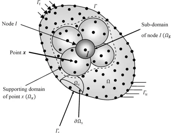
The meshless local Petrov-Galerkin approach is constructed over a local sub-domain which is located inside the global domain. Here, the local sub-domain s is either a sphere or a part of a
sphere. A generalized local weak form of Equation (25) over a local sub-domain s can be written as + + − + + − − =
2 2 2 2 2 2
1
[( ) ( )] ( ) 0
su
n n n n n n
n n
s
p p p F G L
d p p d
t x y z
x y z (33)
where is the test function and su is a part of the boundary s of s which the essential boundary conditions are specified on it. In general, = s s
L
s where s is a part of thelocal boundary located on the global boundary and
L
s .is the other part of the local boundary located in the global domain (Figure 3). In equation (33) a penalty parameter 𝛼 is used to impose the essential boundary conditions. By using
= + + − + +
2
( p) [ ( p ) ( p ) ( p )] ( p p p )
x x y y z z x x y y z z (34)
and the divergence theorem, Equation (32) leads to
+ + − + + + − + + = + + + + − + + −
1 2 3
1 2 3
1 2 3
( ) ( n n )
( n n )
1 1
(F ) (F n n n )
1
(F n
s
su su su
s
n n n n n n
s
n n n
n n
n n n n n n
s
n
p p p p p p
d n d
x x y y z z x y z
p p p
p d n d p d
x y z
G L d G L d
t x y z t
t
1 + n2 + n3) sun n
G L d
(35)
where 𝑛𝑖 (𝑖 = 1, 2, 3)are the components of outward unit normal vector to the sub-domain boundary s usually composed of three parts; the internal boundary
L
s , the boundary for theessential (Dirichlet) conditions su and the boundary for the natural (Neuman) conditions sq .
= = =
1 ˆ 1,2,3,..., M ij i jK p f i M (36)
where =
1 2 3
ˆ [p ,p ,p ,...p ]ˆ ˆ ˆ ˆN T
= = = = = + + + − + + − + +
1 11 2 3 1 2 3
1 1
( )
( n n ) ( n n )
su
s su
J J J
M M
J
I I I
ij
J s J
J J J J J J
M M
I
J J
K d d
x x y y z z
n d n d
x y z x y z
(37) = + + + − + + − + + +
1 2 3
1 2 3
1 1
(F ) (F n n n )
1
(F n n n )
s
su su
n n n n n n
i
s
n n n n
f G L d G L d
t x y z t
G L d p d
t
(38)
3.2 Moving least squares (MLS) approximation
In the MLPG method, the field variable u(x) could be approximated by the MLS technique. This
approximation is based on three components: (1) a weight function of compact support associated with each node, (2) polynomial basis functions, and, (3) a set of coefficients that depend on the position
x
of the point. First, a sub-domain x located in the problem domain and called the domain of definition of the MLS approximation for the trial function at the pointx
is considered.Then, the unknown trial approximation
u
h(x) of the function u(x)is defined using the following equation (Atluri and Zhu 1998).=
=
1
(x) (x) a (x) = p (x)a(x), x
m
T
h j j x
j
u p (39)
In the above equation, pT(x) [p (x),p (x),...,p (x)]= 1 2 m is a vector of the complete monomial basis of order
m
, and a(x)is a vector containing unknown coefficientsa
j(x), j=1,2,...m.Two examples of p (x)T in the three-dimensional problems are as follow (Atluri and Zhu 1998).
= =
p (x) [1,x,y,z] forlinearbasisT m 4 (40)
= 2 2 2 =
p (x) [1,x,y,z,x ,y ,z ,xy,xz,yz]T for quadratic basis, m 10 (41)
The
m
unknown parameters aj(x) can be determined by minimizing the weighted discrete2
L
norm, defined as (Atluri and Zhu 1998):=
=
21
ˆ (x) (x)[p (x ) a(x)-u ]
n
T
i i i
i
where
w
i(x)is the weight function associated with the node i with i(x) >0 for allx
locatedat the domain of influence of
x
i,x
i denotes the regarded node i ,n
is the number of points inthe domain of influence of
x
, x for which the weight functions i(x) >0 (Figure1), andu
ˆirefers the fictitious nodal value and not the nodal value of the function
u
h at the pointx
i.Minimization of J(x) in Equation (42) with respect to a(x)leads to the following linear relation (Atluri and Zhu 1998).
= ˆ
(x)a(x) B(x)u
A (43)
where
=
=
1
(x) (x)p(x )p (x )
n
T
i i i
i
A
(44)= 1 1 2 2
(x) [ (x)p(x ), (x)p(x ),..., n(x)p(x )]n
B
(45)= 1 2
ˆT [ˆ ,ˆ ,...,ˆn]
u u u u (46)
If Equation (43) is solved for a(x), it yields (Atluri and Zhu 1998):
( )
= −1( ) ( )
ˆa x A x B x u (47)
As it can be seen from Equation (47), the unknown coefficients a(x)can be obtained only if (x)
A defined by Equation (43) is non-singular. Hence, a necessary condition for a well-defined MLS approximation is that at least
m
weight functions are non-zero (i.e.n m ) for each sample pointx (Atluri and Zhu 1998).
=
=
1
ˆ ˆ
(x) (x) , (x) u ,x
n
h h
i i i i x
i
u
u
u
u
(48)where
−
=
=
11
(x) (x)[A (x)B(x)]
m
i j ji
j
p (49)
i(x) is usually called the shape function of the MLS approximation corresponding to the node i .The spatial derivatives of the shape function
i(x) are (Atluri and Zhu 1998):( )
(
)
− − −
=
= + +
1 1 1, ,
1 m I
K j k jI j K K jI
j
P A B P A B A B (50)
where(),i ()/
x
i. The derivative of A−1in Equation (50) can be computed by taking the−1= − −1 −1
,K ,K
A A A A (51)
The second partial derivatives of
i(x)are obtained as:( )
(
)
(
)
(
)
− − − − −
− − − −
=
+ + + +
+ + + +
=
1 1 1 1 1
, , , , , ,
1 1 1 1
, , , , , ,
, 1
,
j kl j k L L j L K K
m jI jI jI
I
j KL KL L K K L
KL jI
j
P A B P A B A B P A B A B
P A B A B A B A B (52)
With
−1 = −1 −1 −1− 1 −1+ −1 −1 −1
,KL ,L ,K ,KL ,K ,L
A
A A A A A
A A A
A A A A A
(53)It should be noted that the shape functions i(x )j derived from the MLS approximation do
not satisfy the Kronecker delta criterion
i(x )j
ij . Therefore, they are not nodal interpolantsand the name “approximation” is used, i.e.
u
h(x ) ui ˆi (Figure 2 illustrates the distinctionbetween
u
i andu
ˆi for a simple one dimensional case).This property makes the satisfaction of the essential boundary conditions more difficult than that in the finite element method. Several techniques have been developed to enforce the essential boundary conditions, such as: Lagrange multipliers (Belytschko et al. 1994), modified variational principles (Dolbow and Belytschko 1998), and the penalty method (Atluri and Zhu 1998). In the current research, the penalty method is implemented to enforce the essential boundary conditions.
Figure 1. The illustration for the domain of influence and the domain of integration
3.3 Weight Function
An important ingredient in the meshless method is the weight function introduced in Equation (42). It should be non-zero only over a small neighborhood of a node (the domain of influence) in order to generate a set of sparse discrete equations.
More precisely, on a compact support of a node, it should be positive and increasing as |𝑥 − 𝑥𝑖| is decreasing. Furthermore, it is desirable that i(x)be smooth, if i(x)is C1
continuous, then for the polynomial basis, the shape functions
i(x) are alsoC1continuous (Lu et al. 1994). Here, the Gaussian weight function commonly used for the meshless methods is implemented.( )
− − − − − = 2 2 2exp[ (d / c ) ] exp[ (r / c ) ])
0 d 1 exp[ (r / c ) ]
0 d
k k
i i i i
i i k
i i
I i i
r
x r (54)
where 𝑑𝑖= |𝑥 − 𝑥𝑖| is the distance between the sampling point
x
and the nodex
i, andr
i is the radius of the domain of influence of the weight function i(x). The parametersc
i and kin Equation (54) regulate the shape of the Gaussian weight function i(x). In fact, there is not any accurate theory to determine a proper value for the parameter 𝑐𝑖. Lu et al. recommended a method to choose this constant as the distance from the node
x
i to the third nearest neighboringnode (Lu et al. 1994). The domain of influence
r
i can be chosen asr
i 3.5c
iso that the weightfunction i(x)covers a sufficient number of nodes to ensure the non-singularity of matrix A in
Equation (49). The parameter k in Equation (54) is usually set at 1.
The first derivatives of a Gaussian weight function i(x) can be calculated as:
( )
− − − − − − = 2 2 2
2 2
,
2 (x x ) d exp[ (d / c ) ]
0 d (1 exp[ (r / c ) ])
0 d
k k
i i i i
i i
k k
i i i
i x i i
k r c x r (55)
( )
− − − − − − = 2 2 2
2 2
,
2 ( ) d exp[ (d / c ) ]
0 d (1 exp[ (r / c ) ])
0 d
k k
i i i i
i i
k k
i i i
i y i i
k y y
r c x r (56)
( )
− − − − − − = 2 2 2
2 2
,
2 ( ) d exp[ (d / c ) ]
0 d (1 exp[ (r / c ) ])
0 d
k k
i i i i
i i
k k
i i i
i z i i
k z z
In the case that
d
i is equal to zero, the first derivatives of i(x) may be written as:i x, = i y, = i z, =0 (58)
Similarly, the second derivatives of the weight function can be computed as:
( )
− − − − − + − − − − + = 2 2 2 2 4 2 2 2 2 2 ,2 ( )
2 * exp
(2 2)( )
(1 exp )
0 K k k i i i i k i i K
k i i i
i
i xx I i
i
I i
d k x x d
k d
C
C
r k x x d
C
x d r
C d r (59)
( )
− − − − − − − + − − + = 2 2 2 2 4 2 2 2 2 2 ,2 ( )
2 * exp
(2 2)( )
(1 exp )
0 K k k i i i i k i i K
k i i i
i
i yy I i
i
I i
d k y y d
k d
C
C
r k y y d
C
x d r
C d r (60)
( )
− − − − − − − + − − + = 2 2 2 2 4 2 2 2 2 2 ,2 ( )
2 * exp
(2 2)( )
(1 exp )
0 K k k i i i i k i i K
k i i i
i
i zz I i
i
I i
d k z z d
k d
C
C
r k z z d
C
x d r
C
d r
(61)
−
− −
= = =
− −
2
2 4
, , , 2
2
2 * exp
( ) ( ) ( )
(1 exp )
K
k i
i
i
i xx i yy i zz K
k i
i
i
d k d
C
x x x
r C
C
(62)
More details about these derivatives have been illustrated in Tanojo (2007).
4. Results of numerical examples
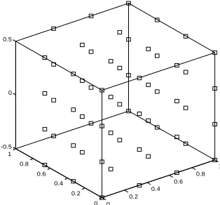
In this section, the introduced strategy based on the meshless local Petrov–Galerkin method is applied to analyze three-dimensional transient incompressible Navier–Stokes equations in two examples. The global domain is considered as a cubic geometry (Figure 4) with 𝑎 = 𝑏 = 1 and the node distribution with 64 regular nodes is regarded (Figure 5) for the both numerical simulations. Furthermore, other effective parameters are set as follows. The final time solution 𝑡 = 0.1, the time step ∆𝑡 = 0.0001, the weight function parameters 𝑐𝑖= 0.4 and 𝑟𝑖= 1.7, the radius of the sub-domain 𝑟𝑜 = 0.01, the penalty parameter 𝛼 = 1017 and finally 𝑅𝑒 = 100.
Figure 4. The cubic geometry for the numerical simulations
Figure 5. The regular node distribution with 64 nodes
4.1 Example 1
Boundary conditions and initial conditions of this example are as follows:
−
= − − − 2 2 /Re
p(0,y,z,t) ( 0.25 0.25cos2y z )e t (63)
−
= − − − 2 2 /Re
p(1,y,z,t) ( 0.25cos(2) 0.25cos2y z )e t (64)
−
= − − − 2 2 /Re
p(x,0,z,t) ( 0.25cos2x 0.25 z )e t (65)
−
= − − − 2 2 /Re
p(x,1,z,t) ( 0.25cos2x 0.25cos(2) z )e t (66)
−
= − − 2 /Re
p(x,y,0,t) ( 0.25cos2x 0.25cos2y)e t (67)
−
= − − − 2 /Re
p(x,y,1,t) ( 0.25cos2x 0.25cos2y 1)e t (68)
− − − 2
p(x,y,z,0)= ( 0.25cos2x 0.25cos2y z ) (69)
The analytical solutions for this problem are:
0 0.2
0.4 0.6
0.8 1
−
= − /Re
(x,y,z,t) sin e t
u
x
(70)−
= − /Re
(x,y,z,t) sin et
v
y
(71)−
= + /Re
(x,y,z,t) (cosx cosy)et
w
z
(72)−
= −1 −1 − 2 2 /Re
(x,y,z,t) ( cos2x cos2y z )e
4 4
t
p (73)
=0
x
f
(74)=0
y
f (75)
−
=2 cos cos 2 /Ret z
f z x y e (76)
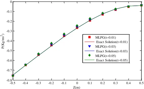
The obtained numerical solutions for the pressure and velocities are shown in Figures 6 through 9 and compared with those of the analytical approach. These comparisons obviously depict the ability and effectiveness of the proposed strategy to solve the three-dimensional fluid flow problems. Moreover, Figures 10 and 13 illustrate the surface plots of the numerical and analytical solutions for the pressure distribution and the velocities. As shown in these figures, the results of MLPG method agree with the values obtained by analytical solution. The convergence of the MLPG approach has been demonstrated in these figures.
Figure 6. The pressure distribution (P (Kg/m2)) for Example 1
-0.5 -0.4 -0.3 -0.2 -0.1 0 0.1 0.2 0.3 0.4 0.5 -0.8
-0.7 -0.6 -0.5 -0.4 -0.3 -0.2 -0.1 0
Z(m)
P
(K
g/
m
s
2)
Figure 7. The velocity of X direction (U (m/s)) for Example 1
Figure 8. The velocity of Y direction (V (m/s)) for Example 1
Figure 9. The velocity of Z direction (W (m/s)) for Example 1
-0.5 -0.4 -0.3 -0.2 -0.1 0 0.1 0.2 0.3 0.4 0.5 -0.9
-0.8 -0.7 -0.6 -0.5 -0.4 -0.3 -0.2 -0.1 0 0.1
Z(m)
U
(m
/s
)
MLPG(t=0.01) Exact Solution(t=0.01) MLPG(t=0.03) Exact Solution(t=0.03) MLPG(t=0.05) Exact Solution(t=0.05)
-0.5 -0.4 -0.3 -0.2 -0.1 0 0.1 0.2 0.3 0.4 0.5 -0.9
-0.8 -0.7 -0.6 -0.5 -0.4 -0.3 -0.2 -0.1 0 0.1
Z(m)
V
(m
/s
)
MLPG(t=0.01) Exact Solution(t=0.01) MLPG(t=0.03) Exact Solution(t=0.03) MLPG(t=0.05) Exact Solution(t=0.05)
-0.5 -0.4 -0.3 -0.2 -0.1 0 0.1 0.2 0.3 0.4 0.5 -1.2
-1 -0.8 -0.6 -0.4 -0.2 0 0.2 0.4 0.6
Z(m)
W
(m
/s
) MLPG(t=0.01)
Figure 10. Surface plots of the numerical and analytical solutions for pressure distribution (P (Kg/m2)) for Example 1
Figure 11. Surface plots of the numerical and analytical solutions for X direction velocity (U (m/s)) for Example 1
r0 U (m/s) V (m/s) W (m/s) P (Kg/ms2)
0.01 7.0194×10⁻³ 6.3572×10⁻³ 1.5506×10⁻³ 5.6371×10⁻³
0.05 7.0194×10⁻³ 6.3572×10⁻³ 1.5506×10⁻³ 3.2735×10⁻³
0.1 7.0194×10⁻³ 6.3572×10⁻³ 1.5506×10⁻³ 5.3504×10⁻³
0.2 7.0194×10⁻³ 6.3572×10⁻³ 1.5506×10⁻³ 4.2712×10⁻³
ri U (m/s) V (m/s) W (m/s) P (Kg/ms2)
1.7 7.0194×10⁻³ 6.3572×10⁻³ 1.5506×10⁻³ 5.6371×10⁻³
3 7.0194×10⁻³ 6.3572×10⁻³ 1.5506×10⁻³ 3.1005×10⁻⁴
5 7.0194×10⁻³ 6.3572×10⁻³ 1.5506×10⁻³ 1.5224×10⁻⁴
Table 2. Obtained errors for different values of radius of the domain of influence of the weight function for Example 1.
Figure 12. Surface plots of the numerical and analytical solutions for Y direction velocity (V (m/s)) for Example 1
Figure 13. Surface plots of the numerical and analytical solutions for Z direction velocity (W (m/s)) for Example 1
M U (m/s) V (m/s) W (m/s) P (Kg/ms2)
125 7.0194×10⁻³ 6.3572×10⁻³ 1.5506×10⁻³ 8.815×10⁻⁵
216 7.0194×10⁻³ 6.3572×10⁻³ 1.5506×10⁻³ 1.129×10⁻⁹
Table 3. Obtained errors for different number of nodes for Example 1.
Table 4. Obtained errors for different values of the time steps for Example 1.
In Table 1, the effect of the value of the radius of the sub-domain has been investigated on the accuracy of the results. For these simulations, N=64, t=0.01, ∆t=0.0001 and ri=1.7 have been
utilized. It can be observed from this table that this parameter doesn’t affect the algorithm accuracy, and the solution process is not dependent on the radius of the sub-domain.
In Table 2, the effect of the value of the radius of the domain of influence of the weight function on the accuracy of the results has been examined with N=64, t=0.01, ∆t=0.0001 and r0=0.01. It can be seen that increasing this parameter would decreased the error and increased the solution accuracy of the pressure distribution.
The results of changing the value of the number of nodes on the velocities and pressure distributions have been studied in Table 3. For these simulations, r0=0.01, t=0.01, ∆t=0.0001 and ri=1.7 have been utilized. It can be noted from this table that increasing the numbers of nodes
would significantly improve the solutions accuracy.
In Table 4, the effect of the value of the time steps has been considered on the accuracy of the results with N=64, t=0.01, ∆t=0.0001, r0=0.01 and ri=1.7 have been utilized. It can be
observed from this table that for small values of this parameter, the algorithm has an acceptable performance.
4.2 Example 2
Boundary conditions and initial conditions of this example is as follows:
−
= − 2+ 2
p(0,y,z,t) 0.5( 2y
z
)e t (77)−
= − 2+ 2
p(1,y,z,t) 0.5(1 2y
z
)e t (78)−
= 2+ 2
p(x,0,z,t) 0.5(
x
z
)et (79)−
= 2− + 2
p(x,1,z,t) 0.5(
x
2z
)et (80)−
= 2− 2
p(x,y,0,t) 0.5(
x
2y )e t (81)−
= 2− 2+
p(x,y,1,t) 0.5(
x
2y 1)et (82)= 2− 2+ 2
(x,y,z,0) 0.5( 2y )
p
x
z
(83)∆t U (m/s) V (m/s) W (m/s) P (Kg/ms2)
0.005 6.8971×10⁻³ 4.7887×10⁻³ 1.9386×10⁻³ 4.5802×10⁻²
0.001 6.9632×10⁻³ 4.0436×10⁻³ 2.1486×10⁻³ 4.1782×10⁻²
0.0005 6.9733×10⁻³ 4.1354×10⁻³ 2.1040×10⁻³ 3.6819×10⁻²
The analytical solutions for this problem are:
−
= − +
(x,y,z,t) (x 2y )et
u
z
(84)−
= − +
(x,y,z,t) (x 2y )et
v
z
(85)−
= − +
(x,y,z,t) (x 2y )et
w
z
(86)= 2− 2+ 2
(x,y,z,t) 0.5( 2y )e
p
x
z
(87)−
= − +(x z) t
y
f e (88)
−
=(2 − ) t
x
f y z e (89)
−
=(2y x)− t
z
f e (90)
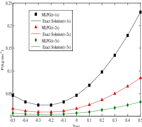
In order to challenge the feasibility and efficiency of the introduced scenario, the pressure distribution and the velocities of three different directions are presented in Figures 14 to 17 for t=1, 2 and 3 s. As evidenced by the overall assessment based on these figures, the extended MLPG method could successfully implemented to analyze three-dimensional transient incompressible fluid flow. Moreover, for more validations, Figures 18 and 19 respectively illustrate the contours of the pressure and X direction velocity distributions. It can be mentioned that according to Equations (84) to (86), the contours of Y and Z directions are same as the presented results in Figure 19. This results are also validated by the obtained results using the MLPG method.
Figure 14. The pressure distribution (P (Kg/m2)) for Example 2 -0.50 -0.4 -0.3 -0.2 -0.1 0 0.1 0.2 0.3 0.4 0.5 0.05
0.1 0.15 0.2 0.25
Z(m)
P
(
kg/
m
s
2)
Figure 15. The velocity of X direction (U (m/s)) for Example 2
Figure 16. The velocity of Y direction (V (m/s)) for Example 2
-0.5 -0.4 -0.3 -0.2 -0.1 0 0.1 0.2 0.3 0.4 0.5 -0.2
-0.1 0 0.1 0.2 0.3 0.4 0.5 0.6
Z(m)
U
(m
/s
)
MLPG(t=1s) Exact Solutiont=1s) MLPG(t=2s) Exact Solution(t=2s) MLPG(t=3s) Exact Solution(t=3s)
-0.5 -0.4 -0.3 -0.2 -0.1 0 0.1 0.2 0.3 0.4 0.5 -0.2
-0.1 0 0.1 0.2 0.3 0.4 0.5 0.6
Z(m)
V
(m
/s
)
Figure 17. The velocity of Z direction (W (m/s)) for Example 2
Figure 18. Surface plots of the numerical and analytical solutions for pressure distribution (P (Kg/m2)) for Example 2
-0.5 -0.4 -0.3 -0.2 -0.1 0 0.1 0.2 0.3 0.4 0.5 -0.2
-0.1 0 0.1 0.2 0.3 0.4 0.5 0.6
Z(m)
W
(m
/s
)
Figure 19. Surface plots of the numerical and analytical solutions for velocities distribution for Example 2
r0 U (m/s) V (m/s) W (m/s) P (Kg/ms2)
0.01 1.5485×10⁻³ 1.5485×10⁻³ 1.5485×10⁻³ 2.3343×10⁻⁸
0.05 1.5485×10⁻³ 1.5485×10⁻³ 1.5485×10⁻³ 2.2735×10⁻⁸
0.1 1.5485×10⁻³ 1.5485×10⁻³ 1.5485×10⁻³ 1.7504×10⁻⁸
0.2 1.5485×10⁻³ 1.5485×10⁻³ 1.5485×10⁻³ 3.2952×10⁻⁸
Table 5. Obtained errors for different values of the radius of the sub-domain for Example 2.
ri U (m/s) V (m/s) W (m/s) P (Kg/ms2)
1.1 1.5485×10⁻³ 1.5485×10⁻³ 1.5485×10⁻³ 1.3024×10⁻⁴
1.3 1.5485×10⁻³ 1.5485×10⁻³ 1.5485×10⁻³ 2.3454×10⁻⁸
1.7 1.5485×10⁻³ 1.5485×10⁻³ 1.5485×10⁻³ 1.7504×10⁻⁸
2 1.5485×10⁻³ 1.5485×10⁻³ 1.5485×10⁻³ 9.6643×10⁻⁹
Table 6. Obtained errors for different values of radius of the domain of influence of the weight function for Example 2.
M U (m/s) V (m/s) W (m/s) P (Kg/ms2)
64 1.5485×10⁻³ 1.5485×10⁻³ 1.5485×10⁻³ 1.7504×10⁻⁸
125 1.5485×10⁻³ 1.5485×10⁻³ 1.5485×10⁻³ 4.2523×10⁻⁹
216 1.5485×10⁻³ 1.5485×10⁻³ 1.5485×10⁻³ 2.7484×10⁻¹¹
Table 7. Obtained errors for different numbers of nodes for Example 2.
∆t U (m/s) V (m/s) W (m/s) P (Kg/ms2)
0.05 1.5485×10⁻³ 1.5485×10⁻³ 1.5485×10⁻³ 2.3454×10⁻⁸
0.01 3.0792×10⁻⁴ 3.0790×10⁻⁴ 3.0789×10⁻⁴ 1.8313×10⁻⁸
0.001 3.0865×10⁻⁵ 3.0838×10⁻⁵ 3.0827×10⁻⁵ 2.0401×10⁻⁸
In Table 5, the effect of the value of the radius of the sub-domain has been investigated on the accuracy of the results. For these simulations, N=64, t=0.1, ∆t=0.05 and ri=1.3 have been
utilized. It can be observed from this table that this parameter doesn’t affect the algorithm accuracy, and the solution process is not dependent on the radius of the sub-domain.
In Table 6, the effect of the value of the radius of the domain of influence of the weight function on the accuracy of the results has been examined with N=64, t=0.1, ∆t=0.05 and r0=0.1. It can be seen that increasing this parameter would decreased the error and increased the solution accuracy of the pressure distribution.
The results of changing the value of the number of nodes on the velocities and pressure distributions have been studied in Table 7. For these simulations, r0=0.1, t=0.1, ∆t=0.05 and ri=1.3 have been utilized. It can be noted from this table that increasing the numbers of nodes
would significantly improve the solutions accuracy.
In Table 8, the effect of the value of the time steps has been considered on the accuracy of the results with N=64, t=0.1, ∆t=0.0001, r0=0.1 and ri=1.3 have been utilized. It can be observed
from this table that for small values of this parameter, the algorithm has an acceptable performance.
5. Conclusion
This study deals with the development of a meshless local Petrov-Galerkin method for solving the three-dimensional transient incompressible Navier–Stokes equations based on the local weak forms. The MLS approximation is used for constructing the trial functions, while the imposition of the essential boundary conditions is carried out by using the penalty approach. Comparisons of the obtained numerical results with the exact solutions reveal that the introduced scenario operates very well in terms of solution accuracy, convergence and reliability.
References
Abidouab D, Sarhand AAD, Yusoffa N, Ghazalia NNN, Awangc MAO, Hassane MA (2018). Numerical simulation of metal removal in laser drilling using meshless local Petrov– Galerkin collocation method, Applied Mathematical Modelling, 56, 239-253.
Andreaus U, Batra RC, Porfiri M (2005). Vibrations of cracked Euler-Bernoulli beams using meshless local Petrov-Galerkin (MLPG) method, Computer Modeling in Engineering & Sciences, 9(2), 111-131.
Arefmanesh A, Najafi M, Abdi H (2008). Meshless local Petrov-Galerkin method with unity test function for non-isothermal fluid flow, Computer Modeling in Engineering & Sciences, 25(1), 9-22.
Arefmanesh A, Najafi M, Nikfar M (2010). MLPG application of nanofluid flow mixed convection heat transfer in a wavy wall cavity, Computer Modeling in Engineering & Sciences, 69(2), 91-118.
Atluri SN and Zhu T (1998). A new meshless local Petrov-Galerkin (MLPG) approach in computational mechanics, Computational Mechanics, 22(2), 117-127.
Atluri SN and Zhu T (2000). The meshless local Petrov-Galerkin (MLPG) approach for solving problems in elasto-statics, Computational Mechanics, 25(2-3), 169-179.
Bagheri A, Ehsany R, Mahmoodabadi MJ, Baradaran GH (2011). Optimization of meshless local Petrov-Galerkin parameters using genetic algorithm for 3D elasto-static problems (technical note), International Journal of Engineering, Transactions A, 24(2), 143-152.
Baradaran GH and Mahmoodabadi MJ (2009). Optimal Pareto parametric analysis of two dimensional steady-state heat conduction problems by MLPG method, International Journal of Engineering, Transactions B, 22(4), 387-406.
Baradaran GH and Mahmoodabadi MJ (2010). Parametric study of the MLPG method for the analysis of three dimensional steady state heat conduction problems, Journal of Mechanical Engineering, 61(1), 31-61.
Baradaran GH, Mahmoudabadi MJ and Sarfarazi MM (2011). Analyze of 3D elasto-static problems by meshless local Petrov-Galerkin method, International Journal of Advanced Design and Manufacturing Technology, 3(2), 37-44.
Batra RC and Ching HK (2002). Analysis of elastodynamic deformations near a Crack/Notch tip by the meshless local Petrov-Galerkin (MLPG) method, Computer Modeling in Engineering & Sciences, 3(6), 717-730.
Belytschko T, Lu YY, Gu L (1994). Element-free Galerkin methods, International Journal for Numerical methods in Engineering, 37(2), 229-256.
Chen ZJ, Li ZY, Xie WL, Wu XH (2018). A two-level variational multiscale meshless local Petrov–Galerkin (VMS-MLPG) method for convection-diffusion problems with large Peclet number, Computers & Fluids, 164, 73-82.
Darani MA (2017). Direct meshless local Petrov–Galerkin method for the two-dimensional Klein–Gordon equation, Engineering Analysis with Boundary Elements, 74, 1-13.
Dolbow J and Belytschko T (1998). An introduction to programming the meshless Element Free Galerkin method, Archives of Computational Methods in Engineering, 5(3), 207–241. Enjilela V and Arefmanesh A (2015). Two-step Taylor-characteristic-based MLPG method for
fluid flow and heat transfer application, Engineering Analysis with Boundary Elements, 51, 174-190.
Feng WJ, Han X, Li YS (2009). Fracture analysis for two-dimensional plane problems of non-homogeneous magneto-electro-thermo-elastic plates subjected to thermal shock by using the meshless local Petrov-Galerkin method, Computer Modeling in Engineering & Sciences, 48(1), 1-26.
Gu YT and Liu GR (2001). A meshless local Petrov-Galerkin (MLPG) method for free and forced vibration analyses for solids, Computational Mechanics, 27, 188-198.
Gu YT and Liu GR (2001). A meshless local Petrov-Galerkin (MLPG) formulation for static and free vibration analyses of thin plates, Computer Modeling in Engineering & Sciences, 2, 463-476.
Heaney C, Augarde C, Deeks A (2010). Modelling elasto-plasticity using the hybrid MLPG method, Computer Modeling in Engineering & Sciences, 56(2), 153-177.
Honarbakhsh B (2017). Numerical solution of EFIE using MLPG methods, Engineering Analysis with Boundary Elements, 80, 199-217.
Karagiannakis NP, Bourantas GC, Kalarakis AN, Skouras ED, Burganos VN (2016). Transient thermal conduction with variable conductivity using the Meshless Local Petrov–Galerkin method, Applied Mathematics and Computation, 272, 676-686.
Li D, Lin Z, Li S (2008). Numerical analysis of Mindlin shell by meshless local Petrov-Galerkin method, Acta Mechanica Solida Sinica, 21(2), 160-169.
Li ZY, Chen ZJ, Wu XH, Tao WQ (2018). Coupled MLPG–FVM simulation of steady state heat conduction in irregular geometry, Engineering Analysis with Boundary Elements, Corrected proof, available online.
Lu YY, Belytschko T, Gu L (1994). A new implementation of the element free Galerkin method, Computer Methods in Applied Mechanics and Engineering, 113, 397-414.
Mahmoodabadi MJ, Abedzadeh Maafi R, Bagheri A, Baradaran GH (2011). Meshless local Petrov-Galerkin method for 3D steady-state heat conduction problems, Advances in Mechanical Engineering, doi:10.1155/2011/251546.
Mahmoodabadi MJ, Sarfarazi MM, Bagheri A, Baradaran GH (2014). Meshless local Petrov-Galerkin method for elasto-static analysis of thick-walled isotropic laminated cylinders, International Journal of Engineering, Transaction B, 27(11), 1731-1740, 2014.
Mohammadi MH (2008). Stabilized meshless local Petrov-Galerkin (MLPG) method for incompressible viscous fluid flows, Computer Modeling in Engineering & Sciences, 29(2), 75-94.
Najafi M, Arefmanesh A, Enjilela V (2012). Meshless local Petrov-Galerkin method-higher Reynolds numbers fluid flow applications, Engineering Analysis with Boundary Elements, 36(11), 1671-1685.
Rashidi Moghaddam M and Baradaran GH (2017). Three-dimensional free vibrations analysis of functionally graded rectangular plates by the meshless local Petrov–Galerkin (MLPG) method, Applied Mathematics and Computation, 304, 153-163.
Sataprahm C and Luadsong A (2014). The meshless local pertov-Galerkin method for simulating unsteady incompressible fluid flow, Journal Egyption Mathematical Society, 22(3), 501-510. Sladek J, Sladek V, Atluri SN (2004). Meshless local Petrov-Galerkin method for heat conduction problem in an anisotropic medium, Computer Modeling in Engineering & Sciences, 6(3), 309-318.
Sladek J, Sladek V, Krivacek J, Wen PH, Zhang C (2007). Meshless local Petrov-Galerkin (MLPG) method for Reissner-Mindlin plates under dynamic load, Computer Methods in Applied Mechanics and Engineering, 196, 2681-2691.
Sladek J, Sladek V, Stanak P, Zhang C, Wunsche M (2013). Analysis of the bending of circular piezoelectric plates with functionally graded material properties of a MLPG method, Engineering Structures, 47, 81-89.
Sladek J, Sladek V, Zhang C, Wunsche M (2010). Crack analysis in piezoelectric solids with energetically consistent boundary conditions by the MLPG, Computer Modeling in Engineering & Sciences, 68(2), 185-219.
Sladek J, Sladek V, Zhang C, Wunsche M (2012). Semi-permeable crack analysis in magneto electro elastic solids, Smart Materials & Structures, 21(2), 025003.
Soares DJ, Sladek V, Sladek J (2012). Modified meshless local Petrov-Galerkin formulations for elastodynamics, International Journal for Numerical Methods in Engineering, 90(12), 1508-1528.
Tanojo E (2007). Derivative of moving least squares approximation shape functions and its derivatives using the exponential weight function, Civil Engineering Dimension, 9(1), 19– 24.
Vaghefi R, Hematiyan MR, Nayebi A (2016). Three-dimensional thermo-elastoplastic analysis of thick functionally graded plates using the meshless local Petrov–Galerkin method, Engineering Analysis with Boundary Elements, 71, 34-49.
Wu XH, Tao WQ, Shen SP, Zhu XW (2010). A stabilized MLPG method for steady state incompressible fluid flow simulation, Journal of Computational Physics, 229 (22), 8564-8577.