Flexure Based Energy Dissipating Device in Self-Centering Braces
Anila Xhahysaa*
Serap Kahramana
Sadik Can Girgina
a Civil Engineering Department, Dokuz Eylul University, Izmir, Turkey. E-mail: [email protected], [email protected],
* Corresponding author
http://dx.doi.org/10.1590/1679-78255807
Abstract
Self–centering braces, in the current stage of development can accommodate large deformation and force levels. However, there is still a need for improvement of the energy dissipation mechanisms commonly incorporated in these braces. Yield based energy dissipation systems can overcome some of the problems faced with friction-based devices, such as susceptibility to bolt relaxation, long-term creep of friction material and excessive flexing arising in the outer tubes due to friction bolts. However, in these alternative systems multi-wave buckling of the yielding core is present, which is the leading cause of an asymmetric hysteresis of the brace. Hence, in this study, U-shape flexural plates (UFPs) are analyzed as an alternative energy-dissipating device in real scale self-centering braces with a finite element modeling approach. UFP plates yield in flexure and when comparing to direct tension/compression yielding members, they show lower strain demand, resulting in a larger displacement capacity. Implementation of the UFP units in the brace produces a flag shape hysteresis with minimal residual deformation. The proposed system provides some advantages when compared to previous models in terms of increased redundancy, symmetric hysteresis and a more gradual stiffness change.
Keywords
Self-centering brace, energy dissipation, flexure, UFPs, finite element modeling
1 INTRODUCTION
can accommodate up to 3.9% drift in the test frame and have high axial capacity, comparable to available buckling restrained braces (Erochko et al. 2014a, 2014b).
However, there is still need for improvement of the energy dissipating mechanisms incorporated in these braces. Researchers focus so far has been mostly oriented towards the friction based (Christopoulos et al. 2008, Erochko et al. 2013, 2014a, 2014b; Zhu and Zhang 2007, 2008),and yield based energy dissipation systems (Chou and Chung, 2014, Chou and Chen 2015, Chou et al. 2016a, 2016b; Zhou et al. 2015; Xhahysa et al. 2017; Mashal et al.2019). However, in recent works alternative energy dissipation systems have emerged, such as fluidic self-centering braces (Kitayama and Constantinou 2016a, 2016b, 2017), shape memory alloyed wires (Miller et al. 2012),piston based self-centering braces (Haque and Alam, 2017) and magnetorheological fluid braces (Xu et al.2018). As these recent systems are less favorable for mass production of the braces and can possibly lead to higher costs, the optimal energy dissipation mechanisms, can be considered the friction based and yield based mechanisms.
However, in friction-based systems the eccentricity of friction bolts with respect to the tube surface causes significant flexing. Moreover, there is susceptibility to bolt relaxation and long-term creep of friction material, and additionally high velocity change of stiffness was the main cause for considerable peak floor accelerations (Erochko et al. 2013). Whereas in the braces where the energy dissipation was obtained from a steel plate core yielding in tension and compression, residual deformation and local buckling were observed (Zhou et al. 2015).Dissipaters using direct shear, tension, compression mechanisms are less suitable, as they tend to generate large strain demands. Whereas, flexural yielding uses more indirect load paths, lowering the strain demand, hence resulting in a larger displacement capacity (Henry et al. 2009).
Hence, in this study, an alternative energy-dissipating device that can be used as the primary or secondary fuse in self-centering braces is proposed. A set of U-shape flexural plates (UFP) that yield in flexure, provide a low-cost system with a wide and stable hysteresis. Once incorporated in the self-centering braces this mechanism is expected to show a gradual change in stiffness, which is the main factor to avoid peak floor accelerations observed in friction-based systems (Wiebe and Christopoulos 2010, 2011). On the other hand, if compared to previous yielding-based energy dissipating systems, the mobile yielding region within the UFP makes the mechanism more redundant. The proposed solution has been studied by conducting finite element modeling.
2 UFP ENERGY DISSIPATION DEVICE
The steel U-shaped flexural plate (UFP), initially proposed by Kelly et al. (1972), consists of one semicircular part and two straight legs, as shown in Figure 1. The relative movement between these parallel legs results in the flexural deformation of the UFP unit. Ultimate displacements up to 85mm were experimentally achieved in a typical UFP test with no decrease in strength (Baird et al. 2014). A design flexibility for this system, is that it can be designed for a large range of possible displacements and force levels by varying the plate dimensions. Moreover, this unit can be bolted to the structural member, so that if damaged it can be replaced after an earthquake. This dissipater is cheap to fabricate, robust, easy to apply and replaceable. Recently it was successfully applied also as an energy dissipation system in shear walls (Palermo et al. 2005; Baird et al. 2013) and seismic base isolated structures (Suzuki et al. 2005;Konishi et al. 2012; Jiao et al. 2014).
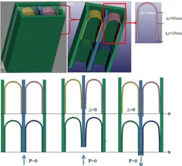
Figure 1: Mini brace with two sets of UFPs (Configuration and loading)
2.1 Configuration and geometry
A mini-brace with one set and two sets of UFPs are analyzed with LS DYNA Software (LSTC 2007) in order to obtain the fundamental properties of their respective hysteretic behavior. The steel plate has cross section dimensions of 8x100 mm, total height of 220mm and is bent with a radius of 60mm, as depicted in Figure 1. Inner and outer tubes are modeled as rigid parts, due to the small ratio length/width of the brace. L1 is the unconstrained length of the UFP, whereas L2 is the length of the UFP leg that is constrained to the inner and outer tube. Meshing was generated with 4mm tetrahedral elements.
2.2 UFP unit material
Selection of the optimal material for the UFP unit production, poses two essential requirements such as cost effectiveness combined with acceptable mechanical properties, namely strength and ductility. Moreover, a major concern for previous self-centering braces was the residual deformation arising from the hardening effect in the core plates (Zhou et al., 2015), hence minimizing this negative effect was a priority in our study. Acceptable candidates for the UFP element generation are both mild and stainless steel. The material modulus of stainless steels reduces with increasing stress, unlike that of carbon steels which is constant. Moreover the residual stresses arising from fabrication are higher in stainless steel than in carbon steels. On the other hand mild steel sheet can be pressed into elaborate panels or can be rolled, and shows ductile behavior as annealed or at elevated temperature. Finally, when using stainless steel, the dissipater is more expensive and its behavior becomes dependent on strain history due to its isotropic hardening, hence mild steel is preferred.
Therefore, the material chosen is JIS SS400, with initial yield stress 255 MPa. Modeling cyclic plasticity of mild steel is of great importance in the analysis of steel UFP plates subjected to cyclic loading. The Yoshida-Uemori model (Yoshida and Uemori 2002) is reported to have a high capacity of simulating metals under cyclic loading within large plastic strain
ranges (around 20%) (Shi et al. 2008).Hence the material type
properties input in the numerical simulation are summarized in Table 1 referring to the previous research database (Jia and Kuwamura 2013).
The following Table 1 provides a reference between symbols used in the original research and variables used in the LSTC keyword.
Table 1. Material parameters input in LS DYNA
Parameter Value
E:=Young's Modulus. 200GPa
PR:=Poisson's ratio. 0.3
CB:=Initial size of the bounding surface (B*) 277 MPa
Y:=Initial yield stress (σy0*) 255 Mpa
SC:=Material parameter (C*) 338 MPa
K:=Material parameter to describe the hardening rate of the bounding surface (m*) 7.9
RSAT:=Maximum change in size of the bounding surface (Rsat*) 196 MPa
SB:=Anisotropic parameter associated with work-hardening stagnation (b*) 195 MPa
H:=Formulation option (h*) 0.5
* Respective material parameter symbols in the reference
2.3 Loading
In previous research (Zhou et al. 2015) the performance of core plates as energy dissipating mechanisms in self centering braces was experimentally tested. In this study reference is done to the loading regime used in these experiments so that comparison of the respective hysteresis of UFP unit and core plate can be conducted thereafter. In order to determine the ultimate target displacement, assumption is made that the brace is installed at a 30° angle in an actual frame, for a target interstory drift of 2%.
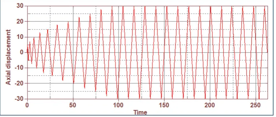
In the previous research, a displacement-controlled loading protocol with equal amplitude incremental displacements was used, namely ∆y, 2∆y, 3∆y, ...,where ∆y, is the overall brace deformation quantity at first significant yield of the core plate. In our case the same logic of loading protocol is adopted, but instead of conducting two equal cycles, the second cycle displacement is selected larger than the previous one. For instance, instead of being ∆y, ∆y, 2∆y, 2∆y..., the new loading regime used is ∆y, 1.6∆y, 2∆y, 2.6∆y,..,as depicted in Figure 2,in order to simulate a worse seismic scenario.
The other difference arises from the fact that the core plate and the UFP unit have different yielding displacements. Therefore, cyclic loading for the low cycle fatigue check starts at ∆=16.8mm and∆=30mm displacement, for the core plate and UFP unit respectively.
2.4 Analysis results
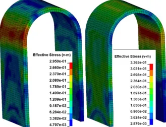
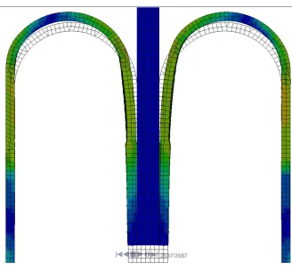
From the analytical results, it is obvious that the yielding region of the specimen occurs where the curvature changes as depicted in Figure 3. Thus, the yielding point of the plate is moved back and forth along the plate during the cyclic loading regime, resulting in a redundant system with expected ample hysteresis cycles.
This yielding pattern was also observed in the UFP plates experimentally tested in previous research (Baird et al.2014). In Figure 3 is presented the propagation of the yield surface in time, and it is evident how in the forthcoming time step the yielding region is moved along the plate. The hysteresis produced thereof is plotted in Figure 4, where the results form one single set of UFP and two sets of UFPs are overlapped.
It is important that the initial and post-elastic stiffness, yield and ultimate force of the UFP unit, are precisely quantified, so that there is certainty that the system will be activated during the seismic event. The system yield displacement and load are respectively ∆y=6.1mm and Fy=27.2kN. From the analysis results the ratio of ultimate to yield load is 147%, which is within the range suggested by Kelly et al (1972),namely 145-215%.
Table 2. Hysteretic parameters of 1&2 UFP sets
Variable 1 UFP set 2 UFP sets
∆y (Yield displacement) 6.1mm 6.1mm
Fy (Yield load) 13.6kN 27.2 kN
ki (Initial stiffness) 2.23 kN/mm 4.46 kN/mm
Fu (Ultimate load) 20kN 40 kN
kp (Post-yield stiffness) 0.265 kN/mm 0.53kN/mm
Moreover, from the hysteresis graph a relevant output is the additive behavior of the UFP units within the brace. Initial stiffness, yield and ultimate load are linearly proportional to the number of UFPs used in the brace as presented in Table 2. Whereas the yield displacement is the same for both specimens, not depending in the number of UFPs that are incorporated in the set analyzed. Hence, for the same deformation level, the maximum effective plastic strain is the same in both specimens. This provides a crucial advantage that the system will activate early, even when high strength level is required from the system. In brief, the main parameters of the hysteresis of a n-set of UFPs can be easily generated from one single set data. This provides significant simplicity to the design process, which is translated in minimal deviances for the macro-system behavior.
Figure 4: Load(kN)-Displacement(mm) curve of 1 (red) & 2 (blue) UFP set
Figure 6: UFP deformation in the final state
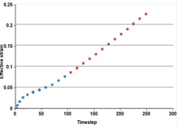
It was previously mentioned that the yielding region of the specimen occurs where the curvature changes, however a thorough analysis of the strain evolution in time of the element is needed. As defined by the geometry of the unit the maximum strain in the plate was found to be 6.3%. The maximum effective v-m strain generated in the element whenever the UFP unit was maximally displaced in the positive direction is depicted in Figure 5. Referring to the strain evolution graph, the effective strain before starting the 15 cycles of loading is 7.6%, whereas the ultimate strain is 22%. The strain increases in a more rapid way once the 15 loading cycles start. However, the maximum strain values plotted in Figure 5 are within the limits of the material ultimate strain suggested by previous research (Jia and Kuwamura 2013).
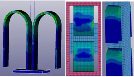
The ultimate UFP plate deformation is depicted in Figure 6. In this step we can provide a comparison with the previously tested core plate as energy dissipating mechanism in the self-centering braces. In their work (Zhou et al. 2015) it was reported that at the load displacement of 28mm the core plates showed fractures near the notch at the inner tube welding length. Multiple wave buckling occurred during compression; hence friction arose between the core plates and the tubes. Whereas in the UFP system, for the same level of displacement d=28mm, there are no fractures in the plate and there is no strength degradation of the system. Moreover in an experimental research the UFP specimen showed no strength degradation up to approximately 80mm axial displacement, which proves that the system is far more redundant and ductile than the core plate.
3 DUAL TUBE CONCEPT
Figure 7: (a) Brace section with UFP energy dissipation (b) Double tube in motion
As in the previous self-centering braces, the outer and inner tube serve for pushing the tendons and restraining the energy dissipation mechanism, in order to have a predefined hysteresis. This working mechanism avoids the usage of a third member, which was previously needed in yield-based self-centering braces (Chou et al. 2016b) to restrain the core plate. Therefore, it reduces the brace complexity in design and application, and consequently reduces its weight and cost. In this brace basalt fiber-reinforced polymer BFRP tendons are chosen instead of the metallic strands used in previous versions as the prestressing system, due to their lower elastic modulus and a higher elastic elongation than a prestressed metallic strand, and lower cost than other fiber strand tendons. Moreover, previous research has shown that the cyclic elastic modulus of the aramid fiber is 1.5–2 times larger than monotonic loading (Christopoulos et al. 2008). Whereas, the ratios of the ultimate elastic modulus to the initial elastic for BFRP tendons vary only1.02-1.12 under cyclic loading (Zhou et al. 2015).
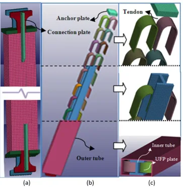
In Figure 8 are presented the structural details of the UFP dual tube SC Brace modeled with LS DYNA, with its main sub-systems, respectively 10 sets of UFPs as the energy dissipation mechanism and the prestressing system. Full brace is depicted in Figure 8a, where only the outer tube, anchor plate and the connection plates are visible. In order to get a better view of each of the elements composing the brace, a partial 3-step brace decomposition is presented in Figure 8b. The outer tube is removed first in order to visualize the inner tube and the UFP units, whereas in the last step the inner tube is removed as well so that the tendons anchored in the anchor plate can become visible.
Figure 8: UFP dual tube self-centering brace configuration (a) Full brace (b) Partial decomposition of brace in 3 steps (c) Representative brace slices
When the brace is subjected to tensile forces, the inner tube moves leftward and the outer tube rightward, together with the UFP legs attached to each of them. This telescope like motion of the tubes activates flexure in the UFP units, which provide the energy dissipation mechanism in this system. Tendons remain always in tension with the prestressing force that is responsible for the self-centering of the system. The compressive behavior of the brace follows the same logic of the tensile state. This flexural-based yielding is different from previous yield based self centering braces, where compression or tension was activated in the yielding core plate depending on the overall brace loading regime. This makes the new brace hysteresis more favorable to a symmetric behavior.
4 BRACE MECHANICS
Based on the working mechanism of the brace, we observe that the UFP set and the dual tube system work in parallel. Hence, the total hysteresis curve can be obtained by directly adding the hysteresis response curves of the two systems together, as shown in Figure 9. The hysteretic curve of the prestressed dual tube system is presented in Figure 9a, whereas in Figure 9b is depicted the hysteretic curve of the UFP set. The final curve of the two systems merged is presented in Figure 9c.
Figure 9:Load- displacement curve of (a) prestressed dual tube system (b) UFP set (c) Brace
When the brace is at rest, the initial pretension P applies compressive force to the inner tube and the outer tube, relative to their axial stiffness; hence the brace shows a relatively high initial stiffness ke1 upon loading until activation is reached. Initial stiffness cannot be defined by the axial stiffness of the brace members alone, but also the axial stiffness of the connection plates kcp should be included in order to obtain the real initial stiffness. Hence the pre-activation stiffness of the brace theoretically can be expressed as in the following equation
(
0)
10
i t cp
e
i t cp
k k k k
k
k k k k
+ +
=
+ + +
(1)This stiffness is denoted as a “theoretical value”, because in reality the tube length difference can reduce it significantly (Erochko et al. 2014a, 2014b).After activation, the UFP plates are still in the elastic phase, and before reaching the yield displacement (Δty), the system shows a lower stiffness than ke1; that is affected by the UFPs (ke2) and tendon elastic stiffness (kt). Beyond this point the stiffness of the system is basically equal to the tendons stiffness (kt), as the UFPs plate post yield stiffness is relatively low. However including again, the effect of the connection plate axial stiffness, the resulting post-elastic stiffness of the system can be expressed as
t cp pe t cp
k k
k
k k
=
+
(2)Upon unloading the initial stiffness of the UFP plates is activated again, until the yield displacement is reached. In case the pretension force is less than the yield force of the UFPs including the effect of hardening, residual deformation (ur) may be present in the system.
5 FLAG SHAPE HYSTERESIS OF THE BRACE
plastic material properties. The parameters that were found to best match the experimental results were combined cyclic hardening with a Q-infinity of 120MPa and Hardening Parameter of 4.5.
Prestress in the system is provided by BFRP tendons, with elastic modulus 40GPa. Initial prestress force in the specimens 1 and 2 is chosen 34kN and 240kN, respectively. These values are larger than the ultimate force produced by the UFP sets, namely 22kN and 220kN, in order to avoid residual deformations.
For a 30° angle brace installation in an actual frame, the elongation of the brace is 0.89% in case an interstory drift of 2% is targeted. This yields a corresponding 26.7mm axial deformation of the brace. Tendons are modelled with the material type “071 Cable Discrete Beam”, and prestress is applied as an initial tensile force “F0”. Automatic surface to surface contact between surfaces coming together after some time is applied. The database binary plot has a time step of 0.01.
5.1 Specimen 1
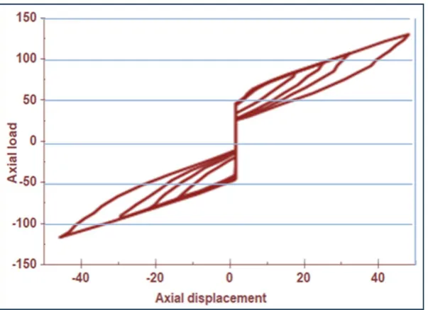
The loading protocol is displacement controlled, with 4 cycles of increasing amplitude. Each cycle amplitude is respectively 2Δy, 4 Δy, 6Δy and 8Δy, where Δy is the overall brace deformation quantity at first significant yield of the UFP unit. The specimen hysteresis is shown in Figure 10. The flag shape hysteresis curve shows that the self-centering system is working properly. We recall here the previous experimental results (Baird et al. 2014), which showed that the ratio of maximum force generated in the UFP under negative/positive loading was ~1.09. This explains the approximately symmetric behaviour of the new system when loaded in tension and compression, as shown in Figure 10. For each cycle the maximum positive and negative force in the brace are respectively (+70kN/-73kN; +82/-86kN; +92/-96kN; +114/-118kN). This behaviour conforms to one of the main requirements for braces that limits this ratio up to 1.3. Previous SCED (Zhou et al. 2015) braces with core plates yielding in tension/compression showed asymmetry during tension and compression cycles, due to multi-wave buckling of core plates causing friction between the core plates and the tubes. On the other hand, when compared to friction based SCED braces, this new system provides a more gradual stiffness change in the high velocity range. This can possibly avoid the peak floor acceleration that was observed in frames that incorporated friction based SCED braces (Erochko et al. 2013).
Figure 11: Load(kN)- displacement (mm) curve of Specimen 2
5.2 Specimen 2
In this specimen 10 sets of UFPs are used in order to check the brace overall performance and the resulting flag shape hysteresis. Prestress in this system is generated by 4Φ14 BFRP tendons. The loading protocol is displacement controlled, with 3 cycles (only with positive displacement) of increasing amplitude. Each cycle amplitude is respectively 3Δy, 6Δy and 9Δy, where Δy is the overall brace deformation quantity at first significant yield of the UFP unit. The specimen hysteresis is shown in Figure 11.
It was experimentally concluded (Baird et al. 2014) that for strain values of 6.3%, no failure data were reported hence the researchers expected that the UFP could undergo 150 cycles before failure. In Figure 13 is presented the change in the post-yield stiffness of the system when different number of tendons are used, as previous research has found that one of the most important factors affecting residual drift is the post-yield stiffness of the inelastic mechanism (Mac Rae and Kawashima 1997). As expected, the post-yield stiffness of the system is directly related to the prestress system, namely a higher tendon area or stiffness, causes an increase in the post-yield stiffness of the brace.
Figure 13:Load(kN)-displacement(mm) curve of Specimen 2 for different prestress systems
Load distribution in this brace and the moving yielding region within the UFP, makes the system more redundant than the previous friction based or yield based SCED braces, where concentrated forces arose in the friction mechanisms or buckling occurred in the yielding regions. A previous study (Xhahysa et al. 2017) compared a possible UFP SCED brace with a previously tested brace which consisted of a 7.86 m long dual core specimen, that had BRB (Buckling Restrained Brace) incorporated inside (Chou et al. 2016b). In order to obtain the required load capacity, instead of the BRB in the original configuration, a set of 15 double UFPs was assumed. The set of UFPs could provide the necessary ultimate resistance and the displacement capacity, if they are to substitute the original BRB energy dissipating mechanism in the brace. On the other hand, a significant decrease in weight was obtained.
6 CONCLUSIONS
This study has presented the performance of an alternative self-centering brace with a new energy dissipation mechanism based on UFP plate flexural yielding. The main outcomes of this analysis performed with the finite element software LS DYNA are as follows:
• The new systems are more redundant than previous yield based SCED models, as the moving yielding region is distributed uniformly over many elements.
• Additive performance of UFP set shows that:
o The yield displacement is the same for all specimens, not depending in the number of UFPs that are incorporated in the set analyzed.
o Initial stiffness, yield and ultimate load are linearly proportional to the number of UFPs present in the set. • Both braces with UFP energy dissipation mechanism analytically tested showed a flag shape hysteresis, confirming
• The brace maximum load when subjected to the same displacement in tension and compression is approximately the same, whereas previous models with core plates yielding in tension/compression, showed asymmetry during tension and compression cycles, due to multi-wave buckling of core plates causing friction between the core plates and the tubes.
• When compared to friction-based braces, the new system provides a more gradual stiffness change. This can possibly avoid the peak floor acceleration that was observed in frames that incorporated friction-based SCED braces. As a result, the alternative brace with a new energy dissipating mechanism proposed in this paper provides the necessary strength and deformation capacity, and at the same time is a cost-effective solution, with several advantages when compared to the previous mechanisms.
Author’s Contributions: Conceptualization, A Xhahysa and S Kahraman; Formal analysis, A Xhahysa; Investigation, A Xhahysa; Methodology, A Xhahysa and S Kahraman; Software, A Xhahysa and SC Girgin; Supervision, S Kahraman; Validation, A Xhahysa and SC Girgin; Visualition, A Xhahysa; Writing - original draft, A Xhahysa; Writing - review and editing, A Xhahysa and SC Girgin.
Editor: Marcílio Alves.
References
Baird, A., Palermo, A., Pampanin, S., (2013). Controlling seismic response using passive energy dissipating cladding connections. In: New Zealand Society for Earthquake Engineering Conference, New Zealand.
Baird, A., Smith, T., Palermo, A., Pampanin, S., (2014). Experimental and numerical study of U-shape flexural plate (UFP) dissipators. In: Technical Conference and AGM, Auckland, New Zealand.
Chou, CC., Chen, YC., (2015). Development of steel dual-core self-centering braces: quasi-static cyclic tests and finite element analyses. J. Earthquake Spectra 31(1):247-272.
Chou, CC., Chung, PT., (2014). Development of cross-anchored dual-core self-centering braces for seismic resistance. Journal of Constructional Steel Research 101:19-32.
Chou, CC., Chung, PT., Cheng, YT., (2016a). Experimental evaluation of large-scale dual-core self-centering braces and sandwiched buckling-restrained braces. J. Engineering Structures 116:12-25.
Chou, CC., Tsai, WJ., Chung, PT., (2016b). Development and validation tests of a dual-core self-centering sandwiched buckling-restrained brace (SC-SBRB) for seismic resistance. J. Engineering Structures 121:30-41.
Christopoulos, C., Tremblay, R., Kim, HJ., Lacerte, M., (2008). Self-centering energy dissipative bracing system for the seismic resistance of structures: development and validation. Journal of Structural Engineering 134(1):96-107.
Erochko, J., Christopoulos, C., Tremblay, R., (2014a). Design and testing of an enhanced-elongation telescoping self-centering energy-dissipative brace. Journal of Structural Engineering 141(6):11-22.
Erochko, J., Christopoulos, C., Tremblay, R., (2014b). Design, testing, and detailed component modeling of a high-capacity self-centering energy-dissipative brace. Journal of Structural Engineering 141(8):12-24.
Erochko, J., Christopoulos, C., Tremblay, R., Choi, H., (2010). Residual drift response of SMRFs and BRB frames in steel buildings designed according to ASCE 7-05. Journal of Structural Engineering 137(5):589-599.
Erochko, J., Christopoulos, C., Tremblay, R., Kim, HJ., (2013). Shake table testing and numerical simulation of a self-centering energy dissipative braced frame. J. Earthquake Engineering & Structural Dynamics 42(11):1617-1635.
Haque, A., Alam, M. S., (2017). Hysteretic behaviour of a piston based self-centering (PBSC) bracing system made of superelastic SMA bars–a feasibility study. J. Structures 12: 102–14.
Jia, L. J., &Kuwamura, H. (2013). Prediction of cyclic behaviors of mild steel at large plastic strain using coupon test results. Journal of Structural Engineering, 140(2), 04013056.
Jiao, S., Kishiki, D., Ene, S., Yamada, N., (2014). Deformation capacity and hysteretic behavior of U-Shaped Steel Dampers for seismic isolated-buildings under dynamic cyclic loadings. In: Tenth U.S. National Conference on Earthquake Engineering, Anchorage, Alaska.
Kelly, J. M., Skinner, R. I., Heine, A. J., (1972). Mechanisms of Energy Absorption in Special Devices for use in Earthquake Resistant Structures. Bulletin of the New Zealand Society for Earthquake Engineering 5(3).
Kim, H. J., Christopoulos, C. (2008). Friction damped post-tensioned self-centering steel moment-resisting frames. Journal of Structural Engineering 134(11):1768-1779.
Kitayama, S., Constantinou, M. C., (2016a). Probabilistic collapse resistance and residual drift assessment of buildings with fluidic self-centering systems. J. Earthquake Engineering & Structural Dynamics 45 1935–53.
Kitayama, S., Constantinou, M. C., (2016b). Seismic response analysis of single-degree-of-freedom yielding structures with fluidic self-centering systems. J. Engineering Structures 125: 266–279.
Kitayama, S., Constantinou, M. C., (2017). Fluidic self-centering devices as elements of seismically resistant structures: description, testing, modeling, and model validation. Journal of Structural Engineering 143 04017050.
Konishi, Y., Kawamura, N., Terashima, M., Kishiki, S., (2012). Evaluation of the fatigue life and behavior characteristics of U-shaped steel dampers after extreme earthquake loading. In: 15th World Conference on Earthquake Engineering, Lisboa, Portugal.
Lin, Y. C., Sause, R., &Ricles, J. M. (2013). Seismic performance of steel self-centering, moment-resisting frame: hybrid simulations under design basis earthquake. Journal of Structural Engineering, 139(11), 1823-1832.
LSTC (2007). LS-DYNA User’s Manual, Livermore Software and Technology Corporation, Livermore, CA, USA.
MacRae G. A, Kawashima, K., (1997) Post-earthquake residual displacements of bilinear oscillators. Earthquake Engineering & Structural Dynamics 26(7):701-716.
Maffei, J., Telleen. K., Nakayama, Y., (2008). Probability- based seismic assessment of buildings, considering post- earthquake safety. J. Earthquake Spectra 24(3):667–699.
Mashal, M., Palermo, A., Keats, G., (2019). Innovative metallic dissipaters for earthquake protection of structural and non-structural components. J. Soil Dynamics and Earthquake Engineering 116:31-42.
Miller, DJ., Fahnestock, LA., Eatherton, MR., (2012). Development and experimental validation of a nickel–titanium shape memory alloy self-centering buckling-restrained brace. J. Engineering Structures 40:288-298.
Palermo, A., Pampanin, S., Buchanan, A., Newcombe, M., (2005). Seismic design of multi-story buildings using laminated veneer lumber (LVL). In: New Zealand Society of Earthquake Engineering Conference, Wairaki, New Zealand.
Priestley, MN., Sritharan, S., Conley, JR., Pampanin, S., (1999). Preliminary results and conclusions from the PRESSS five-story precast concrete test building. PCI Journal 44(6):42-67.
Qu, Z., Wada, A., Motoyui, S., Sakata, H.,Kishiki, S. (2012). Pin-supported walls for enhancing the seismic performance of building structures. Earthquake Engineering & Structural Dynamics 41(14): 2075-2091.
Ricles, JM., Sause, R., Garlock, MM., Zhao, C., (2001). Post-tensioned seismic-resistant connections for steel frames. Journal of Structural Engineering 127(2):113-121.
Rojas, P., Ricles, JM., Sause, R., (2005). Seismic performance of post-tensioned steel moment resisting frames with friction devices. Journal of Structural Engineering 131(4):529-540.
Shi, M. F., Zhu, X. H., Xia, C., Stoughton, T., (2008). Determination of nonlinear isotropic/kinematic hardening constitutive parameters for AHSS using tension and compression tests. Proc., Numisheet 2008,Institute of Virtual Manufacturing, ETH Zurich, Zurich, 137–142.
Wada, A., Qu, Z., Ito, H., Motoyui, S., Sakata, H., Kasai, K. (2010). Seismic retrofit using rocking walls and steel dampers. In Improving the Seismic Performance of Existing Buildings and Other Structures (pp. 1010-1021).
Wiebe, L., Christopoulos, C., (2011). Using Bezier curves to model gradual stiffness transitions in nonlinear elements: Application to self-centering systems. J. Earthquake Engineering & Structural Dynamics, 40(14), 1535-1552.
Wiebe, L., Christopoulos, C. (2010). Characterizing acceleration spikes due to stiffness changes in nonlinear systems. J. Earthquake Engineering and Structural Dynamics, 39(14),1653-1670.
Xhahysa, A., Kahraman, S., Girgin, S., (2017). Alternative energy dissipating device in self-centering braces – UFP Plate. İn: ICCE International Conference of Civil Engineering, Tirana, Albania.
Xu, L. H., Xie, X. S., Li, Z. X. (2018). A self-centering brace with superior energy dissipation capability: development and experimental study. J. Smart Materials and Structures, 27(9), 095017.
Yoshida, F., Uemori, T. (2002). A model of large strain cyclic plasticity describing the Bauschinger effect and work hardening stagnation. International Journal of Plasticity 18(5-6), 661–686.
Zhou, Z., Xie, Q., Lei, XC., He, XT., Meng, SP., (2015). Experimental investigation of the hysteretic performance of dual-tube self-centering buckling-restrained braces with composite tendons. Journal of Composites for Construction 19(6):13-26. Zhu, S. Y., Zhang, Y. F., (2007). Seismic behavior of self-centering braced frame buildings with reusable hysteretic damping brace. J. Earthquake Engineering & Structural Dynamics 36: 1329–46 .