IJIRT 145198
INTERNATIONAL JO URNAL OF INNOVATIVE RESEARCH IN TECHNOLOGY630
Reduction in BER in FSO Using Amplify and Forward
Relaying Techniques
Kishore Yadav
1, Dr. V.S. Chauhan
21
M.Tech Students, Department of Electronics Engineering, MBM Engineering College Jodhpur
2
Professor, HOD, Department of Electronics Engineering, M BM Engineering College Jodhpur
Abstract- Multihop free space optical (FS O) system using optical amplify-and-forward (OAF) relaying technique combine with wavelength division multiplexing (WDM) is proposed for all -optical access networks. The proposed system can provide a low cost, flexible, and high-bandwidth access network for multiple users. To investigate the system performance, we consider a special case of dual-hop WDM-FS O system taking into account the effects of all noises, inter channel crosstalk, as well as path loss and geometric spreading of optical beam over atmospheric turbulence channels. In addition, pulse position modulation (PPM)is employed for improving the overall performance. Our results show that OAF technique combined with PPM scheme can be a good solution for mitigating the effect of atmospheric turbulence. Moreover, the required amplifier gain corresponding to a specific value of BER, transmission distance, and turbulence strength is quantitatively discussed. Finally, the adverse effect of inter channel crosstalk in the upstream transmission is also evaluated.
I.INTRODUCTION
Free Space Optical Link
Free Space Optics (FSO) is a communication technology that uses light as a carrier and free space as medium to transfer information between two terminals.. This technique is widely known as Optical Wireless Communication (OWC). With increase in number of users, demand for bandwidth in
communication is increasing significantly.
Applications like mobile, video conferencing etc. requires large amount of bandwidth, so the coming communication technology must be able to handle such higher data rates. Current technologies have lots of limitations and cannot handle such applications
efficiently. Performance of technologies like
copper/coaxial cables, RF (microwave) and optical fiber is limited because of problems like congested
spectrum, lower data rate, expensive licensing, security issues and high cost of installation. Relay -assisted FSO transmission which was introduced in context of the radio frequency (RF) cooperative relaying protocols, has been popularly used as a fading mitigation tool. In the cooperative RF systems, the source broadcasts information to multiple relays, which forward the information to the destination. However, unlike the RF counterpart, the FSO systems are non-broadcasting in nature. Hence, the source needs to be equipped with a multi-laser transmitter for each relay node, with the total source power divided amongst the multiple source-relay links.
II. SYSTEM MODEL
The object of the communication system is to transfer data or information from a transmitter at one point to a receiver at another point through the atmospheric channel within acceptable error rate while providing high reliability. The FSO link comprises of three basic subsystems - transmitter, channel and receiver Alternative transmission protocols which can be applied to relay-assisted FSO systems with no LOS between the source and the destination.
IJIRT 145198
INTERNATIONAL JO URNAL OF INNOVATIVE RESEARCH IN TECHNOLOGY631
Today’s FSO systems use either lasers or LEDs (light emit- ting diodes) to transmit a modulated beam of visible/infrared light .These systems are license-free with high-bandwidth capacity providing a cost-effective and easy-to-install alternative to fiber optics. They further provide an inherent security due to the nature of their 6 directional and narrow beams which make eavesdropping and jamming nearly
impossible. With its unique features, FSO
communication is appealing for a number of applications including last-mile access, fiber back- up, back-haul for wireless cellular networks, and disaster recovery.
IIITRANSMITTER
The primary function of the transmitter is to modulate the information onto the optical carrier which then propagates and reaches the receiver after
propagating through the atmosphere. Optical
transmitter essentially consists of (a) modulator, (b) driver circuit that stabilizes the optical radiation from the optical source in case of fluctuations in temperature and (c) telescope, that collects the radiation, collimates it and finally directs it towards the receiver. The most widely used modulation is the intensity modulation (IM) in which the source data is modulated on the irradiance/intensity of the optical signal. The main idea behind cooperative diversity is based on the observation that in a wireless RF channel, the signal transmitted by the source node is overheard by other nodes, which can be defined as partners or relays. The source and its partners can
jointly process and transmit their information, creating a virtual antenna array although each of them is equipped with only one antenna The main idea behind cooperative diversity is based on the observation that in a wireless RF channel, the signal transmitted by the source node is overheard by other nodes, which can be defined as partners or relays. The source and its partners can jointly pro cess and transmit their information, creating a virtual antenna array although each of them is equipped with only one antenna.
Multihop transmission is an alternative relay-assisted transmission scheme which employs the relays in a serial configuration Such schemes are typically used to broaden the signal coverage for limited - power
transmitters and do not offer performance
improvement against fading effects in wireless RF environments, i.e., it does not increase the diversity order.
IV RECEIVER
The primary function of the receiver is to recover the transmitted data from the incident optical radiation. It consists of a receiver telescope, optical filter, photo -detector and a demodulator. The receiver telescope collects and focuses the incoming optical radiation onto the photo-detector. The optical filter reduces the level of background radiation and directs the signal onto the photo-detector that converts the incident optical signal into an electrical signal.
V OPTICAL AMPLIFY-AND-FORWARD RELAYING TECHNIQUE
IJIRT 145198
INTERNATIONAL JO URNAL OF INNOVATIVE RESEARCH IN TECHNOLOGY632
Fig:-1 An All-Optical multihop FSO Communication System
VI. OAF RELAY STRUCTURE
In OAF relaying, there is at least one optical amplifier which amplifies the receivedoptical field and retransmits it to the next relay. The structure of a typical OAF relayis simply shown in Fig.1 As mentioned, there is a converging lens at the beginningof each relay that collects and focus es the incident light onto the back focal plane ofthe lens, a plane normal to the lens axis placed at distance ffocal behind the lens. The complex amplitude distribution of the field in the focal plane of the lens is the Fraunhofer diffraction pattern of the field incident on the lens. This field distributionis projected onto a single mode fiber (SMF).
Figure-2 Structure of OAF Relays
The SMF is connected to the optical amplifier that is mathematically modeled as
( ) √ ( ) ( ) (1)
where ( ) and ( ) are the received and
transmitted signals at the kth relay respectively, G is the kth amplifier gain and ( ) is the amplified spontaneous emission (ASE) noise of thekthamplifier. The ASE noise is modeled as an additive zero-mean white Gaussian noise. The spectral density of ASE noise is given by .
̅ ( ) (2)
VII OPTIMAL RELAYING CONFIGURATION
relays are placed at fixed stations between the source and destination nodes. It is important to arrange relays such that the best system performance is achieved at the receiver. In this section, the performance of the system is analyzed in terms of the average optical signal-to-noise ratio (SNR) at the receiver. In the considered multihop sys tem, relays are consecutively placed between the source (k =0) and destination (k = M+ 1) nodes. Figure-3 shows an optical Amplify-and- Forward multihop system with M relays, where OAF relays are typically shown as amplifiers. The hop distance, Lk ,which is the length ofthe link connecting the (k-1)thnode to the kthnode varies for different relays. Let denotes the transmitted signal at
Figure:3 Optical Amplify-and-Forwardmult ihop FSO Systems
the source, the received field at the jthrelay,, j = 1,2....M + 1, is expressed as
(∏ √
) ( ∑ ∏ √
)
( ∑ ∏ √
) (3)
Assuming that the signal, background noise, ASE noise and fading are all independent, the average received power at the receiver (j = M+ 1) is
(∏
)
( ∑ ∏
)
(
∑ ∏
) (4)
IJIRT 145198
INTERNATIONAL JO URNAL OF INNOVATIVE RESEARCH IN TECHNOLOGY633
(∏ )
( ∑ ∏ ) ( ∑ ∏ ) (
)
Typically amplifier spontaneous emission noise PASE is negligible with respect to data power Ptand background noise power Pb, therefore Eq.(5) can be approximated as
(∏ )
( ∑ ∏ ) (6)
By substituting euations, and performing some simplifications, the average optical SNR is expressed as
[∏ ( )] (7)
WhereSNRk is the average receive SNR at the receiver of a direct FSO link ( where there is no relay between transmitter and receiver) with length Lk :
SNRk =gk SNR0 (8)
The path loss gkdepends on the hop distance Lk .Now,SNRM+l must be optimized with respect to Lk'S. Consider the optimization problem
∑
(9)
Figure:4 An OAF multihop FSO System with M= 1
VII.FIXED TOTAL COMMUNICATING DISTANCE
Consider an FSO system where the some and destination nodes are placed at a total communicating distance of LT= 3 km from each other. In this section, by placing a different number of relays (different M) between the source and destinationnodes, the significant role of relaying technique in improving the performance of thesystem is justified. In order to simulate the FSO system in the slowly-varying optical channel, 107 bits are transmitted per channel state. At both bit rates, 64 samplesper bit interval are provided. In the presence of atmospheric turbulence,
the BER is averaged over NT= 1000 different fading conditions to reasonably simulate the slow-fading turbulence channel.
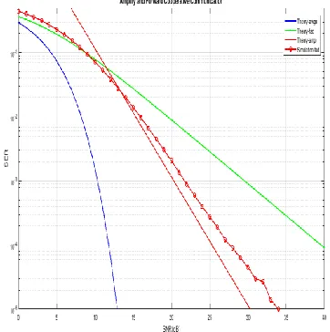
The overall performance of the system for different number of relays, M, placedbetween the source and destination is analyzed by plotting the BER versus the transmit signal-to-noise ratio SNR0 = Pt/Pb.Fig.5 and 6 correspond to the systems working at bit rates BR= 1.25 Gbps andBR= 10 Gbps respectively. The turbulence fading effects are not considered in these plots. Table 1 summarizes the configuration, i.e., number of relays and hop distance, of the systems considered in these figures.
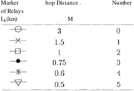
The overall performance of the system only depends on the average transmit SNR0 and the relaying configurations, gk. By comparing two figures, Table 1: Different system configurations for LT= 3 km.
Marker hop Distance . Number
of Relays
Lk(km) M
IJIRT 145198
INTERNATIONAL JO URNAL OF INNOVATIVE RESEARCH IN TECHNOLOGY634
Figure :5 BER versus SNR0 for a 3 km link and different number of relays M at BR= 1.25 Gbps, no
fading effect is considered.
At both bit rates, for a given SNR0, by shortening th e hop distances via inserting more relays between communicating nodes (increasing M), BER at the destination node decreases. its shown in Fig.5 and 6, inserting one relay at the middle of a3 km link gains 2.49 dB improvement at BER = 10-5Here the effects of atmosphericfading are not considered. Thus this gain mainly comes from the reduction in pathloss achieved by shortening the hop distances.
Figure:6 BER versus SNR0 for a 3 km link and different number of relays M at BR= 10 Gbps, no
fading effect is considered.
Simulation
In this Paper the major objective that we have discussed
1) Mitigation of atmospheric turbulence by more no of relays
2) Comparison of the FSO signal transmission with and without AF RELAYING which we can clearly observe reduction into BER
3) Large bandwidth signal can also propagate through AF relaying technique
4) If no of relays has been increase then more reduction in BER occur
This paper presents new optical relaying techniques to mitigate atmospheric turbulence induced fading effects and eliminate background noise in free space optical (FSO) communication systems. The main contributions of the thesis are proposing all-optical amplify-and-forward (OAF) relaying technique and applying them to relay assisted FSO systems. In order to define an all optical relay-assisted FSO system, a new channel model is developed which characterizes the variations of intensity and phase of the optical signal during wave propagation. An additive AWGN channel is assumed in which background illumination is the dominant source of noise. Three primary factors have been considered to model the free space channel effects:
1) Atmospheric attenuation which includes both absorption and scattering contributions
2) log-normal fading under weak atmospheric turbulence conditions
3) Propagation loss due to optical beam spreading through optical channel. The Beers -Lambert law is modified to find the atmospheric attenuation factor applied to the optical field envelope. Since the optical field envelope is analyzed, both amplitude and phase of atmospheric-induced fading are statistically modeled and new definition for propagation loss is defined.
IJIRT 145198
INTERNATIONAL JO URNAL OF INNOVATIVE RESEARCH IN TECHNOLOGY635
Fig:8 comparison of BER when Pt =100 mW
Fig:9comparison of BER with and without relay when Pt =1,10,100 miliwatt
The numerical results show that the new model for propagation loss is close to the conventional model (geometric loss), however, the proposed model
provides more accurate estimation of beam
propagation loss especially over short ranges (a few hundred meters). The OAF relaying technique is proposed as a powerful technique for mitigating the atmospheric turbulence-induced fading while all relaying processes , e.g. amplification, filtering (as needed) etc. are performed in optical domain.
Fig-10 BER if total transmit power distribution for different percentage to source and relay (source have more power compare to relay)
Fig:-11BER if total transmit power distribution for different percentage to source and relay (source have less power compare to relay)
It is numerically shown that by increasing the number of relays between source and destination, hop distances decrease and consequently distance-dependent atmospheric-induced fading is mitigated. In fact by employing more OAF relays, longer communicating distances are accessible for a given
average transmit power. FSO communication
systems suffer extensively from atmospheric
turbulence and background noise.
IV. CONCLUSIONS
We investigated transmission protocols for relay -assistedFSO systems Increasing the number of relays
is accompanied by collecting more additive
background noise at relays that degrades the system
performance. Therefore, to reach a specific
communicating distance at a given BER, a tradeoff is compromised between the average transmit power and the number of relays. Since the average transmit power is limited due to eye-safety regulations, the
number of relays determines the maximum
IJIRT 145198
INTERNATIONAL JO URNAL OF INNOVATIVE RESEARCH IN TECHNOLOGY636
REFERENCES
[1] Q. Liu et al., “Optical wireless communication networks for first- andlast-mile broadband access [Invited],”J. Opt. Netw., vol. 4, no. 12, pp.807– 828, Dec. 2005.
[2] D. J. Heatley et al., “Optical wireless: The story so far,” IEEECommun. Mag., vol. 36, no. 12, pp. 72–82, Dec. 1998
[3] E. Ciaramella et al., “1.28 Terabit/s (32 x 40Gbit/s) WDM transmissionsystem for free space optical communications,”IEEE Journal onSelected Areas in Communications, Vol. 27, No. 9, pp. 1639-1645, Dec.2009.
[4] D. W. Young et al., “Demonstration of high data
rate wavelengthdivision multiplexed
transmission over a 150 km FSO link,”Proc.of Military Communications Conference, Orlando, USA, pp. 1-6, Oct.2007.
[5] D. M. Forin et al., “Very high bit rates WDM transmission on atransparent FSO system,” Proc. of 33rd European Conference and Ehxibition of
Optical Communication (ECOC), Berlin,
Germany, pp.1-2, Sept. 2007.
[6] SalasiahHitam, et al., “Performance analysis on 16-channels wave-length division multiplexing in free space optical transmission undertropical regions environment,”Journal of Computer Science, Vol. 8,No. 1, pp. 145-148, 201 \
[7] T. Kamalakis, et al., “Hybrid free space
optical/millimeter wave outdoorlinks for
broadband wireless access networks,” Proc. of IEEE 18th Int.Symp. On Personal, Indoor and Mobile Radio Communications,Athens,Greece, 2007.
[8] Abisayo O. Aladeloba, et al., “WDM-FSO
network with turbulence-accentuated
interchannel crosstalk,” Journal of Optical Communication Network, Vol. 5, No. 6, pp. 641-651, June 2013
[9] Y. Arimoto, “Compact free-space optical
terminal for multi-gigabitsignal transmission with a single mode fiber,” Proc. SPIE, Vol. 7199,No. 7, 2009.
[10]X. Zhu and J. M. Khan, “Free-space optical communication throughatmospheric turbulence channels,” IEEE Trans. Commun., vol. 50, pp.1293-300, Aug. 2002.
[11]J. Akella, M. Yuksel, and S. Kalyanaraman “Error analysis of multi-hop free-space optical
communication,” Proc. of IEEE
InternationalConference on Commun., pp. 1777-1781, 2005.
[12]M. Safari and M. Uysal, “Relay-assisted free-space optical communi-cation,” IEEE Trans. Wireless Comm.vol. 7, no. 12, Dec. 2008. [13]C. K. Datsikas et al., “Serial free-space optical
relaying communica-tions over gamma-gamma
atmospheric turbulence channels,” J.
Opt.Commun. Netw., vol. 2, no. 8, Agust 2010 [14]M. Feng, J. B. Wang, M. Sheng, L. L. Cao, X. X.
Xie, M. Chen, “Outageperformance for parallel relay-assisted free-space optical communica-tions in strong turbulence with pointing errors,” Proc. of InternationalConference on Wireless Commun. and Signal Processing (WCSP), pp.1– 5, 2011
[15]T. V. Pham, T. C. Thang, and A. T. Pham, “Performance analysis of multihop FSO systems
using APD receivers over log-normal
channels,”Proc. of the 2nd IEEE/CIC
International Conference on Communica-tions in China,Xi’an, China, pp. 165–170, Aug. 2013. [16]T. V. Pham and A. T. Pham, “Performance of
APD-based amplify-and-forward multihop FSO systems over turbulence channels,” Proc. of the IEEE Globecom 2013 Workshop - Optical Wireless Communications,Atlanta, US, Dec. 2013.
[17]S. Kazemlou, S. Hranilovic, and S. Kumar,
“All-optical multihop free-space optical
communication systems,” J. Lightw. Technol., vol. 29, no.18, pp. 2663–2669, Sept. 2011. [18]E. Bayaki, D.S. Michalopoulos, R. Schober,
“EDFA-based all opticalrelaying in free-space optical systems,” IEEE Trans. Commun., vol. 60,no. 12, pp. 3797–3807 , Dec. 2012
[19]M. A. Kashani et al., “All-optical
amplify-and-forward relaying systemfor atmospheric
Channels,”IEEE Commun. Letters, vol. 16, no. 10, pp.1684–1687 , Oct. 2012
IJIRT 145198
INTERNATIONAL JO URNAL OF INNOVATIVE RESEARCH IN TECHNOLOGY637
[21]R. Ramaswami and K. N. Sivarajan,Optical
Networks–A practicalPerspective 2nd ed.
London: Academic, 2002.
[22]I. T. Monroy and E. TangdionggaCrosstalk in WDM Communication Networks Norwell, MA: Kluwer Academic, 2002.
[23]G. P. Agrawal,Fiber Optic Communication
Systems(John Wiley andSons Inc., third ed., 2002).
[24]M. A. Al-Habash, L. C. Andrews, and R. L.
Philips, “Mathematicalmodel for the
irradiancprobability density function of a laser
beampropagating through turbulent media,