© Universiti Tun Hussein Onn Malaysia Publisher’s Office
IJIE
Journal homepage: http://penerbit.uthm.edu.my/ojs/index.php/ijie
The International
Journal of
Integrated
Engineering
ISSN : 2229-838X e-ISSN : 2600-7916
Development of Shoe Dryer
S
ystem using Microcontroller
with GSM
M
odule
Nurliyana Abd Mutalib
1*, Rostam Affendi Hamzah
1, Navine Arumugam
1,Madiha Zahari
1, DA Hadi
1, Siti Halma Johari
1, N. Ab Wahab
2, Suziana Ahmad
11Faculty of Electrical and Electronic Engineering Technology,
Universiti Teknikal Malaysia Melaka (UTeM), Hang Tuah Jaya, 76100, Durian Tunggal, Melaka, MALAYSIA
2Faculty of Mechanical Manufacturing Engineering Technology,
Universiti Teknikal Malaysia Melaka (UTeM), Hang Tuah Jaya, 76100, Durian Tunggal, Melaka, MALAYSIA
*Corresponding Author
DOI: https://doi.org/10.30880/ijie.2019.11.03.029
Received 7 August 2019; Accepted 20 August 2019; Available online 31 August 2019
1. Introduction
A shoe dryer is one of the things that really needed by people nowadays. The reason existence of products are the defined function of a product itself [1] hence, everybody will agree that wet shoes are not the most pleasant thing especially during the cold or rainy days. Previously, the conventional method used is drying the shoe under the sun thus it takes longer time for people in a hurry. Recently, there are various models for shoe dryer that are multifunctional. However, most of the common product in the market are bulky, expensive and using a lot of energy and takes a longer time to dry the shoes.
This paper focused on the design and development of a shoe dryer with a microcontroller. The designed shoe dryer is capable to improve the existing shoe dryer. It capable to dry the shoe with shorter time frame which controlled by the microcontroller and GSM.Several techniques have been proposed in designing a product. Modern product design grows in importance in multiple engineering disciplines during all stages of design [2]. A reliable shoe dryer needs to have an element of communication so that user will have the freedom to do other work while drying their shoe. The recent development of a shoe dryer, author [3] had developed a smart IoT shoe box which can be controlled with both using an embedded system and a smartphone. The Internet of things (stylized Internet of Things or IoT) which was mention by [4],[5] and [6] is the internetworking of physical devices (also referred to as "connected devices" and "smart
Abstract: This paper describes the design and development of a shoe dryer using a microcontroller. Nowadays, people often travel and sometimes in rainy day, they need to dry their shoe in a very short time anywhere. However, very rare of places including shopping mall and hotel provide a shoe dryer. The shoe dryer is designed to help people who are in hurry to dry their shoe on the go. A temperature sensor is used to measure the temperature inside the shoe dryer, while a program is uploaded in the microcontroller for reading and data collection. The programming includes the activation of shoe dryer with the GSM module, thus it can be controlled using a mobile phone. An experiment was conducted to test the performance of the shoe dryer. The optimum performance was obtained when the temperature is set at 36°C, and timer at 60 seconds with normal room temperature. The temperature and timer need to be adjusted accordingly based on the shoe condition in order to get very satisfying results. This paper proved that the shoe dryer was successfully designed, implemented and analyzed.
devices"). The ultrasonic sensor and temperature sensor in the system will analyze the environment inside the shoe box and automatically adjust the condition to maintain the box normal condition.
The GSM as stated by [7] firstly designed for voice. It is now expandable and can be used for other applications. The author in [8] mention in their project that GSM is the practical way of communication because GSM has worldwide subscribers. In the design, the mobile phone was used to send the message to GSM module which was connected to PIC microcontroller.
Simple shoe dryer apparatus was developed by [9] were it use thermal energy as the source of drying element. This dryer needs the shoe to be in the dryer overnight. It needs almost 5 to 6 hours to completely dry the shoe with the use of high power light bulb. This consumes a lot of time for the user who has a time constraint.
A shoe dryer using heat residues was proposed by [10] to utilize the heat remnants. Thermal energy waste used as an alternative to the electrical heat energy for the dryer. The advantages of the design are that it uses the natural heat energy from the refrigerator to supply to the dryer and the drawback of the design. It just can be used with refrigerator only.
This work, a shoe dryer using PIC16F877A microcontroller which is using temperature and GSM module are designed. The PIC16F877A is a very simple yet practical and commonly used in making a system or product automated. The temperature sensor is used to measure the temperature inside the dryer. A communication module such as GSM can be embedded with the shoe dryer, thus this project considered in using the GSM.
The rest of this paper is organized as follows; section 2 briefly describes the methodology, software and hardware configuration and the experimental setup of the shoe dryer, followed by the results and discussion in section 3. Finally, in section 4, the author concludes the findings of the paper.
2.
Methodology
The justification process of choosing the right components behind the shoe dryer project is based on several factors to ensure the shoe dryer able to perform its tasks efficiently. Fig. 1 shows the block diagram of the shoe dryer system which consists of a temperature sensor, GSM, LCD, Fan, Bulb, DC motor, buzzer and relays used in this work.
Fig. 1 - System block diagram of shoe dryer.
2.1
Block diagram
The core design blocks of systems are shown in fig. 1. Three main components at input stage are the power supply, temperature sensor and the GSM module. A power supply is available in order for the dryer to operate, thus enable the shoe dryer to be placed anywhere. The temperature sensors in which the sensitivity range is between 25 degree °C room temperature and above but less than 36 degrees °C detects temperature and transmit signals in analog form to the microcontroller (PIC16F877A).
The GSM module is used as the communication device between the shoe dryer and the user of mobile phone. The timer and temperature are set in the shoe dryer to operate according to the user data entry from the mobile phone.
PIC16F877A is the microcontroller used for this project. The PIC 16F877A circuit functions as a main unit processor to execute instructions received. This PIC16F877A can be programmed with C language or assembly language using the MP-LAB software. The microcontroller circuit also operates with the voltage of + 5VDC and will receive all input signals and further executes instructions that we have uploaded which contains in the memory. The microcontroller controls the relay that rotates the motor and switch on the fan and light.
Start
Place shoes and send SMS to user
Set Timer Dryer ON
Shoes Dry?
Send SMS notification &
Buzzer Activation
End Yes
N o
A relay is also known as an electronic switch. For activation only takes approximately DC voltage or AC voltage depends on the relay specification. Relay circuit also can decide either DC or AC voltage. For this project, it is used to control motor, fan and lamp. A DC Motor with 10 rpm, rotates 360° to ensure the shoe will completely dry with the help of rotating plate and the fan for good air circulation in the dryer. Lamp and fan are activated when there is command received from the microcontroller. The lamp and fan will start to activate once the shoe detected in the dryer and the user sends SMS of the desired condition for the shoe that needs to be dried. Furthermore, the lamp will also help the shoe to dry completely with the intensity of the light which acts as the heating element in the dryer. The buzzer will be activated once the dryer has completed the time cycle and stop the shoe dryer.
2.2
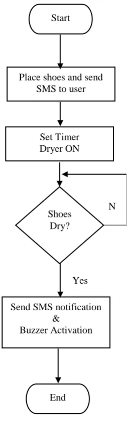
Algorithm
The category of design and validation methods for this shoe dryer is according to the physical design and validation methods. According to fig. 2, the process of drying a shoe started when the shoe is placed in the dryer. An SMS will be received by the user as ‘Shoes Detected’ via the GSM to the mobile phone. The user can start to send the timer and temperature parameter via SMS according to the need of shoe condition.
Upon receiving the command, there will be notification displaying the parameter in LCD on the shoe dryer. The user then starts the shoe dryer by sending the command to start. Once the dryer started, the bulbs and fan will be activated. The temperature sensor senses and check the temperature inside the dryer and send the input to the microcontroller. The microcontroller will ensure the temperature in the shoe dryer is stable as determined by the user during the drying process. The lamps will supply the heat energy in the dryer meanwhile the fan help to circulate the hot air entire the dryer so that the shoe completely dry. The remaining time will be displayed on the LCD. When the process completed, a buzzer activated and SMS will be sent to notify the user.
2.3
Design of shoe dryer
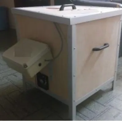
The design of shoe dryer prototype is shown in fig 3. The determination of a model is essential to ensure that the selection of construction materials is made right and appropriate to the project. The shoe dryer system is designed to help travelers or people on the go to dry their shoe at their own convenient time. As shown in fig. 4 is the angle view of the shoe dryer, the shoe dryer body is made of plywood and sealed with aluminum at every corner of the box. It also consists of the lid cover to ensure no thermal lost while drying process takes place. The selection of this plywood is made in the suitability of the project and its durability to accommodate the weight of the shoe and the system. A plastic box is used for electronic circuit placement outside the dryer box.
Fig. 3 - Process of prototyping the shoe dryer.
Fig. 4 - Angle view of the shoe dryer prototype.
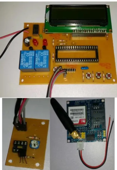
On the software development part, the PIC16F877A microcontroller has been chosen because it is low cost and more practical. The PIC16F877A coding was assembled and compile using C language with MPLAB software. The GSM module was connected to the microcontroller via programming done in the module. It then, being combined with the designed hardware.
Fig. 5 - PIC circuit, Sensor circuit and GSM module.
3.
Results and Discussion
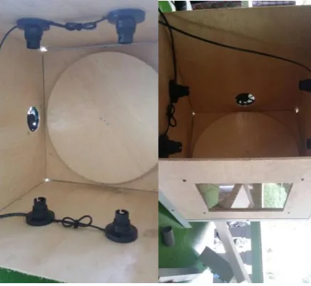
The result and analysis of the designed shoe dryer will be discussed in this section. The overall view of the shoe dryer shown in Fig. 6, fig. 7 and fig. 8. The hardware includes DC Motor to rotate the shoe platform, four light bulbs 5V for each placed at each side of the dryer in order to supply the heat source, and one of exhaust fan to help in circulating the hot air in the dryer, LCD display, relay, power supply, GSM module and PIC16F877A module. The specification of the shoe dryer as shown in table 1. An experiment was conducted to test the functionality and reliability of the designed shoe dryer. The analysis begins with testing on the shoe dryer performance.
Table 1 Specification of shoe dryer.
Parameters Specification Materials Plywood, circuit plastic
box, and wires Size Height 49cm x Width
43cm Speed of motor rotates 10 rpm Shoe space (quantity) 2 shoe
Bulb voltage Each 5V
Power 120V AC household outlet Weight 4 Kg
Fig. 6 - Top view of complete prototype. Fig. 7 - Interior view of complete prototype.
Fig. 8 - Side view of complete prototype.
The validation of parameter for the dryer has been carried out. The shoe dryer has been tested with general different of shoe condition which is wet, slightly wet and dry. And the time and temperature of the dryer also change accordingly. The testing has been done at normal room temperature. Table 2 until Table 4 show the results of the shoe under certain condition setup. In Table 2, the shoe is tested in wet condition. The dryer is placed in room temperature environment which is 27°C. The timer is set for 20 seconds, 40 seconds and 60 seconds accordingly. The temperature of the dryer also set to 30°C, 33°C and 35°C accordingly. Observation found that shoe condition after the drying process was slightly wet at 30°C, slightly dry at 33°C and completely dry at 35°C. Table 3 shows the shoe is tested in slightly wet condition. The dryer is placed in room temperature environment which is 26°C. The timer is set for 20 seconds and 40 seconds accordingly. The temperature is set to 30°C and 33°C accordingly. Observation found that at 30°C, the shoe is still in the same condition before the drying process. However, at 33°C, the shoe is completely dry. Table 4 shows the shoe is tested in dry condition. The room environment for the dryer is 26°C, the timer is set for 20 seconds and the temperature of the dryer is set to 25°C. The shoe condition is dry after the drying process. From the results obtained, it shows that the timer setting for the dryer is an important parameter because in order to ensure the drying process successful, appropriate time setting is required.
Table 2 Parameter for wet condition testing.
Before Monitoring Process After Shoe condition Timer
(s)
Tempera-ture (°C)
Room Tempera- ture (°C )
Shoe condition
Table 3 Parameter for medium wet condition testing.
Before Monitoring Process After Shoe condition Timer
(s)
Tempera-ture (°C)
Room Tempera-ture (°C )
Shoe condition
Slightly wet 20 30 26 Slightly Wet Slightly wet 40 33 26 Dry
Table 4 Parameter for dry condition testing.
Before Monitoring Process After Shoe condition Timer
(s)
Tempera-ture (°C)
Room Tempera-ture (°C )
Shoe condition
Dry 20 25 26 Dry
Fig. 9 shows that the best condition is obtained when the dryer was set at 36°C and in 60 seconds. The timer setting is very significant in drying process. Therefore, it is set as the default setting of the dryer. If the shoe doesn’t dry according to the default setting, then the timer and temperature can be set again until the shoe completely dry.
Fig. 9 - Graph analysis result.
4.
Conclusion
Drying of the shoe in a short time can be troublesome to the people who were in a hurry. The shoe dryer is economical designed and very convenient to use. User capable to dry their shoe within the expected time. Through this project, results of parameter analysis of shoe dryer have been reported in detail.The shoe dryer was tested at different parameters which are shoe condition, time and temperature. The shoe dryer has been designed, developed and tested successfully. As a conclusion that each shoe conditions has a certain time and temperature need to be set accordingly in order to dry the shoe perfectly. The higher the temperature set, therefore less time needed for a shoe to be dry.
This dryer is ready to be used worldwide to help people with a different situation of drying their shoe anywhere. In the future, this shoe dryer features can be enhanced with the self-automated timer and temperature which can adjust the timer and temperature automatically to ensure the shoe dried perfectly and ready to be used again.
ACKNOWLEDGEMENTS
Authors would like to thank Universiti Teknikal Malaysia Melaka (UTeM) and Ministry of Higher Education for sponsoring this research under research grant PJP/2018/FTK(13C)/S01632).
References
[1] Sudin, M., Ramli, F, and Tan, C. Functional modelling approach in the design of an electrical shoe dryer,
Suranaree Journal Science and Technology, Volume 20, No. 4, (2013), pp. 279–287.
[2] Nagel, R. L., Stone, R. B., and Mcadams, D. A. A theory for the development of conceptual functional models for automation of manual processes. Proc. Asme 2007 Int. Des. Eng. Tech. Conf. Comput. Inf. Eng. Conf. Idetc/Cie, (2007) pp. 1–13.
Ubiquitous And Future Networks (Icufn), (2017), pp. 607–609.
[4] Panwar, A and Singh, A., Eyrie smart home automation using internet of things. Computing Conference, (2017) pp. 1368–1370.
[5] Horyachyy, O. Comparison of wireless communication technologies used in a smart home: Analysis of wireless sensor node based on Arduino in home automation scenario, Master Thesis, Blekinge Institute of Technology, Karlskrona, Sweden, (2017)
[6] Oshin, O., Sobowale, S., Oni, O., and Atayero, A. Development of a power-harnessing smart shoe system with outdoor navigation, Proceeding of the World Congress on Engineering and Computer Science, Volume I, (2017). [7] Joseph, G. M., Nwankwo, E. L., Eniola, O. M., and Eneh, C. D. Design of a real-time microcontroller based
GSM-embedded intrusion security system. Internatioanl Journal of Scientific and Enginering Research., Volume 6, No. 12, (2015), pp. 232–241.
[8] Nithya, N and Hemalatha, M. GSM-based cost effective street lighting application. Procedia Eng., Volume 30, No. 2011, (2012), pp. 737–741.
[9] Adnan, M. R. Development of simple shoe dryer apparatus, Project paper, Universiti Malaysia Pahang, (2007). [10] Roslan, M. H., Arifin, K. I. K., and A. A. Hanafi, A. A. M. Heat suction. Politeknik Sultan Haji Ahmad Shah,