CFD Study on Hydrogen-Air Premixed Combustion
in a
Micro Scale Chamber
Shabanian, Sayed Reza; Rahimi, Masoud*
+; Khoshhal, Abbas
CFD Research Center, Chemical Engineering Department, Razi University, Kermanshah, I.R. IRAN
Ammar Abdulaziz Alsairafi
Faculty of Mechanical Engineering, College of Engineering and Petroleum, Kuwait University, KUWAIT
ABSTRACT: This paper reports a CFD modeling study to investigate the hydrogen-air mixture combustion in a micro scale chamber. Nine species with nineteen reversible reactions were considered in the premixed combustion model. The effect of operational and geometrical conditions including; combustor size, wall conductivity, reactant flow rates and hydrogen feed splitting on combustion stability and outlet gas temperature were investigated. The results show that the wall thermal conductivity has a significant effect on the combustion especially at smaller chamber size with high ratio of chamber surface area to its volume. In addition, the results reveal that high heat loss from chamber wall, small chamber and high input rate may cause flame quenching. Moreover, the modeling results indicate that a stable combustion in a micro combustor can be achieved at an optimum operational condition.
KEY WORDS: Micro combustion, Hydrogen-air, CFD, Flame temperature, Heat transfer.
INTRODUCTION
In the recent years, there is a significant increase in the number of consumer, industrial, and military applications utilizing portable electronic equipment, such as laptops, cellular telephones, and personal data assistants. All of these devices require a portable power source, which, most commonly, is provided by batteries. However, for many of these applications, the relatively low energy density of traditional batteries imposes burdensome weight and power limitations on system design. Power generation utilizing hydrocarbons or hydrogen-air systems offers a promising alternative to traditional batteries. The energy
density of hydrogen-air systems is significantly higher than that of batteries (approximately 140 MJ kg−1 compared with 0.5 MJ kg−1 for lithium-ion battery). The combustion based micro power device, such as micro gas turbine engine, is one of the most promising designs due to its high power density. Micro combustor is one of the main components of micro power system uses hydrogen and hydrocarbon as fuels. Considerable experimental and numerical studies have been carried out to investigate the effect of various geometrical and operational conditions on the flame stability limits and performance of micro combustors [1-4].
* To whom correspondence should be addressed.
+E-mail: [email protected]
An experimental investigation was carried out on premixed combustion in cylindrical micro combustors (with a backward-facing step) by Li et al. [5]. They studied the effect of wall temperature and radiation heat flux on the performance of cylindrical micro combustors. Their results showed that as the combustor length increases, the range of flow conditions for successful ignition becomes smaller. It was also shown that the backward-facing step employed in the combustor design is effective in stabilizing the flame position. In continuation of this research, they studied the porous media combustion of premixed hydrogen–air in a planar micro combustor with a channel width of 1 mm [6]. The effects of flow conditions and position of the porous media on both the wall temperature distribution and the emitter efficiency are investigated. Their experimental results indicate that the wall temperature increases with increasing mixture velocity, and higher emitter efficiency is achieved for mixtures with U 0.8.
Cao & Xu [7] investigated the thermal performance of a micro combustor for micro gas turbine system. They found that the wall temperature of the micro combustor and the temperature of the exhaust gas from combustor reach to maximum values at excess air ratio of 0.9. The effect of wall thickness of micro combustor on the performance of micro Thermo Photo Voltaic (TPV) power generators was experimentally investigated by Wenming et al. [8], in their experiments, three kinds of micro cylindrical combustors made from SiC with different wall thickness were tested. The performance of the micro TPV system was measured for various flow rates and hydrogen/air ratios. Their results showed that when the inner diameter of the micro combustor is constant, with the decrease of wall thickness, both maximum electrical power output and short-circuit current increase considerably. In another study, the suppression of radical heat loss to the combustor walls and flame quenching effects was experimentally investigated by Miesse et al. [9]. In their work, methane-oxygen diffusion flames were successfully stabilized between parallel plates having gaps of less than 1 mm. Combustion of methane-oxygen in three types of micro tubes with the outer diameter of 3 mm was experimentally studied by Junwei & Beijing [10]. The obtained results showed that when equivalence ratio was lower than unity, the methane was not completely oxidized and a great amount of hydrogen and carbon
monoxide was produced. The turbulent mixing of a passive scalar in confined multiple jet flows in a micro combustor was investigated by Cho et al. [11]. The authors performed their experiments for a micro combustor having a circular disk baffle plate with a fuel injection nozzle in the center and oxidant injection holes allocated annularly. Their results revealed that the turbulent mixing is promoted by complex flow fields caused by the jet flows and large vortical flow regions. An experimental study performed by Zhou et al. [12] to improve the micro combustion stability using an electrical heating. The authors reported that when electrical heating power of 1.05 and 4.70 W are used, the equivalence ratio ranges of stable combustion are extended from 0.362 - 6.52 to 0.178 - 7.66 and 0.126 - 9.43, respectively. A new micro combustor configuration for a micro fuel cell reformer integrated with a micro evaporator was studied experimentally and numerically by Kim & Kwon [13]. They could extend the flame stability limits of micro combustor.
In addition to above experimentally research in this field, many theoretical works have been carried out by researchers. Raimondeau et al. [14] simulated the methane-air flame propagation in micro tubes by solving the parabolic governing equations. In their model, the discontinuity boundary conditions of temperature and concentration as well as the destruction of radicals at the gas–solid interface were employed. They found that close to entrance the heat loss and radical wall quenching are key parameters in controlling the flame propagation in these types of micro devices. In another investigation, a numerical study of hydrogen-air combustion in micro channels was carried out by Leach et al. [15]. They concluded that heat exchange through the structure of the micro combustor can lead to broadening of the reaction zone (flame thickness).
In another research, the effect of different wall material on the performances of catalytic micro combustor investigated by Zhou et al [17]. Their CFD computations depicted that the thermal conductivity and inlet flow rates influenced the mode of combustion. Heterogeneous micro combustion prevailed at higher wall thermal conductivity and low flow rates.
Kaisare & Vlachos [18] also tried to find suitable reactor length, reactor opening size and wall thickness for homogeneous combustion in parallel plate narrow channels. They solved the simplified one-dimensional governing equations and used single-step reaction mechanism for this purpose. The flammability in terms of blowing-off and flashing-back were recognized at different conditions.
Li et al. [19] developed a simple 1D flame model to analyze the heat transport occurring in the cylindrical micro combustors. They extend the model of Li et al. [20,21] to quantify two important ratios, namely, the heat loss ratio (the ratio of the heat loss from the flame to the heat generation in the reaction zone) and the heat recirculation ratio (the ratio of the heat recirculation through the solid structure to the upstream to the heat loss from the flame). As an improvement over Li et al. model [20,21], the one-step global reaction mechanisms were included.
The effects of various parameters such as the combustor size, fuel property, fuel–air equivalence ratio and unburned mixture temperature on the heat loss ratio and the heat recirculation ratio were investigated. Their results indicated that these parameters have significant effects on the two ratios, and therefore should be carefully managed in order to achieve efficient and stable combustion. A numerical investigation was performed by Chen et al. [22] to study the effects of catalytic walls on hydrogen-air flames in a micro tube. Their results showed that the combustor channel wall and the fuel mixture characteristics can play a significant role in micro channel combustion.
In the above mentioned modeling studies, regarding to this fact that the combustion chamber characteristic length and gas flow path are larger than the molecular mean free path, the fluid continuity is established and Navier-Stokes equations and no-slip wall condition are employed in micro combustion such as conventional combustion in macro systems. However, some parameters such as heat wall conductivity that are not
important in macro combustion, should be considered in micro combustion modeling.
Due to progresses in computer hardware and software and consequent increase of the calculation speed, the Computational Fluid Dynamics (CFD) modeling technique would be a powerful and effective tool for understanding the complex hydrodynamics in many industrial processes. Since measuring instrument causes disturbance to the micro flame, thus CFD modeling can be a suitable way to study this type of process [23] with vanishing interference of experimental sensors in flow hydrodynamics.
A two-dimensional CFD study was carried out by Benedetto et al. [24] to investigate the opportunity of setting up a novel scheme of micro combustors. In that study, the combustor was divided into two parts. In the first part, the walls of the micro combustor were coated with catalyst, while in the second part the catalyst was absent and only homogenous combustion could taken placed. Numerical results showed that this hybrid micro combustor allows operating at high inlet gas velocities and thus high input powers, without encountering blow-out and maintaining almost complete fuel conversions. In continuation of their research [25], Benedetto et al. studied the effect of the cross-sectional geometry on the ignition-extinction behavior of catalytic micro combustors. For this purpose, two different types of circular and square cross-section were investigated. Stability maps were built and compared with lean propane-air combustion at different inlet gas velocities. Results demonstrated that at low inlet velocities the square cross-section channel has more resistance to extinction than the cylindrical one.
In most of the theoretical studies dealing with micro combustors, two-dimensional CFD models have been adopted [26-28]. Two-dimensional models neglect the circumferential changes of velocity, temperature, species concentration as well as heat and mass fluxes. At the small-scales, these variations are important. Therefore, ignoring of these variations may causes incorrect theoretical predictions for micro scale combustion systems.
main issue in this study. The hydrogen-air mixture is chosen for three main reasons: (1) the reaction mechanism is well known; (2) the reaction mechanism is simpler compared to other hydrocarbon fuels; (3) the hydrogen-air flame is more practicable to be sustained in micro scale combustors. For this purpose, a cylindrical combustor with a fixed diameter/length ratio was modeled using three dimensional CFD modeling technique.
THEORY
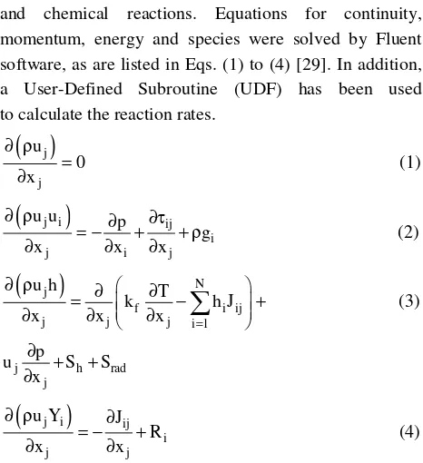
The micro combustion modeling involves the solution of the laminar flows with heat transfer, species transport and chemical reactions. Equations for continuity, momentum, energy and species were solved by Fluent software, as are listed in Eqs. (1) to (4) [29]. In addition, a User-Defined Subroutine (UDF) has been used to calculate the reaction rates.
( )
j ju 0 x
∂ ρ =
∂ (1)
(
j i)
iji
j i j
u u p
g
x x x
∂ ρ ∂ ∂τ
= − + + ρ
∂ ∂ ∂ (2)
(
)
Nj
f i ij
j j j i 1
u h T
k h J
x x x =
∂ ρ ∂ ∂
= − +
∂ ∂ ∂ (3)
j h rad
j
p
u S S
x
∂
+ +
∂
(
j i)
ij ij j
u Y J
R
x x
∂ ρ ∂
= − +
∂ ∂ (4)
Where ρ is the fluid density (kg/m3), u is velocity (m/s), p is the static pressure (Pa), is the laminar stress tensor (Pa),
ρg is the gravitational body force per unit volume (N/m3). h, kf and T are the sensible enthalpy (kJ/kg), thermal conductivity (W/mK) and temperature (K) of fluid mixture, respectively. Moreover, hi is the sensible enthalpy of species i (kJ/kg), Jij is the diffusion flux of species i in the j direction (kg/m2s), which was the combination of full multi component diffusion and thermal diffusion. In addition, N is the total number of gas species, Sh is the source of energy caused by chemical reaction (kW/m3) and Srad is the source of radiation obtained from the solution of discrete ordinates radiation model equations. Finally, Yi is mass fraction of species i, Ri is the net rate of production of species i by chemical reaction (kg/m3s).
Table 1: The grid independency study results.
No. of control volume
Predicted adiabatic flame temperature
Difference percentage
148 563 2505.5
203 975 2450.8 2.183197 %
322 495 2420.4 1.240411 %
500 027 2408.0 0.512312 %
855358 2407.6 0.016611 %
CFD MODELING
A three-dimensional CFD modeling of the reactive gas flow in the micro combustor was performed using the commercial CFD code, Fluent 6.2. [30]. The CFD modeling was carried out to find the behavior of combustion of hydrogen-air mixture in a cylindrical micro chamber. Moreover, the effect of various boundary conditions on flame characteristics has been investigated.
Geometry and mesh generation
In the present study, the micro combustor was created and meshed using GAMBITTM. The inlet duct diameter and length were one-half and one-fourth of the reactor's diameter, respectively. The modeled domain which consists of two cylindrical chambers was meshed into almost 500000 tetrahedral cells. This mesh layout was found by examination of different cell sizes as no further significant change was found for finer cells in predicted adiabatic flame temperature. This temperature has been calculated by modeling of hydrogen-air combustion in the studied combustor under adiabatic condition. The results of this grid consistency study for the combustion chamber is presented in Table 1. As it is illustrated in this table, the values of calculated temperature using grids 4 and 5 are quite close. In the other words, no significant changes were observed in the predicted temperature for grid 5 when it is compared with that of grid 4. Therefore, Grid 4 setup was chosen due to the lower required computation time. Fig. 1 shows the meshed configuration of the inlet tube and the combustion chamber.
Initial and boundary conditions
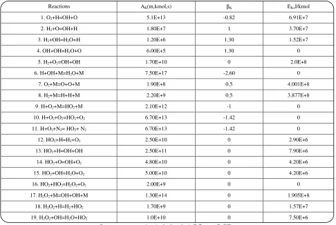
Table 2: Gas phase reaction mechanism for hydrogen-air combustion [31,32].
Reactions AK(m,kmol,s) βK EK,J/kmol
1. O2+H=OH+O 5.1E+13 -0.82 6.91E+7
2. H2+O=OH+H 1.80E+7 1 3.70E+7
3. H2+OH=H2O+H 1.20E+6 1.30 1.52E+7
4. OH+OH=H2O+O 6.00E+5 1.30 0
5. H2+O2=OH+OH 1.70E+10 0 2.0E+8
6. H+OH+M=H2O+M 7.50E+17 -2.60 0
7. O2+M=O+O+M 1.90E+8 0.5 4.001E+8
8. H2+M=H+H+M 2.20E+9 0.5 3.877E+8
9. H+O2+M=HO2+M 2.10E+12 -1 0
10. H+O2+O2=HO2+O2 6.70E+13 -1.42 0
11. H+O2+N2= HO2+ N2 6.70E+13 -1.42 0
12. HO2+H=H2+O2 2.50E+10 0 2.90E+6
13. HO2+H=OH+OH 2.50E+11 0 7.90E+6
14. HO2+O=OH+O2 4.80E+10 0 4.20E+6
15. HO2+OH=H2O+O2 5.00E+10 0 4.20E+6
16. HO2+HO2=H2O2+O2 2.00E+9 0 0
17. H2O2+M=OH+OH+M 1.30E+14 0 1.905E+8
18. H2O2+H=H2+HO2 1.70E+9 0 1.57E+7
19. H2O2+OH=H2O+HO2 1.0E+10 0 7.50E+6
Rate constants are given in the form k=AKT βKexp (-EK/RT).
Enhancement factors:H2O=20.0 , Enhancement factors:H2O=6.0, H=2.0, H2=3.0. Enhancement factors : H2O=21.0, H2=3.3, O2=0.0, N2=0.0
Fig. 1: The modeled micro combustor.
were defined at the inlet side. No-slip boundary condition was imposed at the combustion chamber wall. Combustion was initiated by introducing a small high temperature zone within the reaction zone to simulate ignition. The initial mass fractions of all species were set equal to their respective inlet values. The influence of the gravitational force on the flow was not taken into account.
Physical properties and chemical reactions
In the present study, fluid flow regime is assumed laminar, as it is, and the fluid density has been calculated using the ideal gas law. The fluid mixture specific heat, viscosity, and thermal conductivity have been calculated using mass fraction weighted average of species properties. The specific heat of each species has been calculated using a piecewise polynomial of temperature. In order to model the gas-phase reaction, a detailed hydrogen-air oxidation mechanism, which listed in Table 2, has been employed. This reaction mechanism includes 9 species and 19 elementary reactions.
Solution strategy and convergence criterion
The whole modeling was carried out in steady state mode of calculations. The SIMPLE pressure–velocity coupling algorithm, the standard pressure and the second order upwind discretization scheme for momentum were employed in the model. In addition, the CFD simulation 2D
L
convergence is judged upon the residuals of all governing equations and the reported results related to residuals less than 1.0 × 10⁻⁶. A double precision, segregated solution solver is used to solve the governing equations.
RESULTS AND DISCUSSION
In this study, the performance of a micro combustor has been investigated using three dimensional CFD modeling. The performance of the combustor is evaluated under various geometrical and operational conditions, including: chamber size, wall heat conductivity, fuel-air flow rate and splitting the hydrogen feed. These results may be used as design guidelines and recommendations for the future development of micro combustion systems.
Model Validation
In order to validate the CFD model, a comparison is done with the measured adiabatic flame temperatures and combustion product composition found by Glassman & Yetter [33]. The comparison results are illustrated in Table 3. With trusting to the observed reasonable agreement between the theoretical and experimental results, the effects of various process operational conditions on hydrogen-air combustion have been investigated.
Effect of feed flow rate
In this section, the effect of feed flow rate on operational stability has been investigated. For this purpose, a combustor with an inlet diameter of 0.42 mm has been modeled. The feed fuel/air equivalence ratio of 0.75, the wall convection coefficient of 200 W/m2.K and ambient temperature of 300 K are considered as boundary conditions in the model. The geometry of studied chamber can be found in Fig. 1. The predicted temperatures at the flame core, which is place of maximum temperature, at various feed flow rate are shown in Fig. 2.
The results show that the flame temperature increased sharply with increasing of feed flow rate at low flow rates due to the fact that the increase of inlet velocity can establish more heat generation per unit time. Consequently, the results reveal that the temperature reaches to a maximum value about 2000 K at feed mass flow rate of 0.001 g/s. No future considerable change in temperature can be observed with the increase of the feed flow rate up to 0.003 g/s. However, at higher feed flow rate the predicted temperature reveal a decreasing trend. These
Table 3: A Comparison between the modeling results and experimental measurement (pressure=1 atm & =1).
Temperature/ composition
Experimental measurement
(Glassman & Yetter, 2008) Modeling results
H 0.0020 0.0021
H2 0.0150 0.0160
H2O 0.3230 0.3150
N2 0.6440 0.6440
OH 0.0070 0.0075
O2 0.0050 0.0052
T(K) 2382 2408
Fig. 2: The flame temperature versus gas mixture mass flow rate for the micro combustor.
results confirm that the feed flow rate has an optimum range which is from 0.001 to 0.003 g/s at the above mentioned operation condition. These CFD predicted results can be explained by a fact that at low flow rate, due to low rate of generated heat in comparison with the rate of heat loss, the combustion process can not be self sustained and the flame will be quenched. Moreover, with increase of input flow rate the flame can be more stable as more heat releases from the reaction. However, with increase of the feed flow rate more than this optimum values, the effective reactant residence time decreases and the reactant have less time for reaction. On the other hand, at higher gas flow rate the convection heat transfer coefficient of product gas increases. Therefore, reduction in flame temperature is expected. In the other words, a stable combustion can be happened in almost 0.001 to 0.003g/s feed mass flow rate, the other two sides,
0 0.001 0.002 0.003 0.004 0.005 0.006
Mass flow rate (g/s) 2500
2000
1500
1000
500
0
F
la
m
e
te
m
p
er
a
tu
re
(
K
Fig. 3: The temperature distribution in an axial slice inside the micro combustor for different flow rates.
less than 0.001 and more than 0.003, which involves with a very high temperature gradient, an unstable flame is expected. The temperature distributions in an axial slice of micro combustor at four different mass flow rates are shown in Fig. 3. It can be seen from the figure that the flame core (high temperature zone) shifts toward the downstream from the inlet as the mass flow rate increased. In addition, Fig. 3 illustrates the thermal quenching of micro scale combustion at low and high feed flow rates as compared with normal flames formed at moderate feed flow rates. Therefore, at very low as well as very high feed flow rates due to lack of existence of high temperature outlet gas and stable combustion, the system cannot work efficiently.
In summary, the above obtained results reveal that the flame temperature and position can be changed by variation of inlet gas velocity. In other words, the maximum temperature shifts toward the exit by increasing the gas velocity while extinction can be occurred by lowering the inlet gas flow rate. This is in agreement with the results obtained by Yang et al.[3]. They found that increasing the gas velocity has contrary effects on combustion. They explained these effects by analyzing the flow residence time and released energy. A similar result was obtained by Li et al. [34] for methane-air combustion system.
Effect of the combustor size
It is well known that the effect of heat loss from combustion chamber in micro scale is more significant than the conventional combustion. This is more important
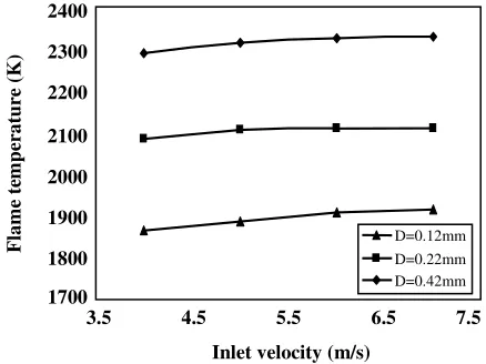
Fig. 4: Effects of combustor size on the flame temperature in various inlet velocities.
in cases that the energy loss cannot be compensated by the heat released from reaction at flame zone, which leads to the flame quenching. Therefore, in this part the effect of combustion chamber size on flame temperature has been studied. For this purpose, three combustors with the inlet diameters of 0.12, 0.22 and 0.42 mm have been modeled. The results have been analyzed for four inlet velocities of 4, 5, 6 and 7m/s layouts. In addition, the heat transfer coefficient on the outer wall is kept at 50 W/m2.K. The variations of flame temperature at various inlet velocities for three mentioned combustors are given in Fig. 4.
As can be seen in this figure, for each chamber size there is not a considerable difference in flame temperature at various employed feed velocities. However, there are significant differences among the predicted flame temperatures for these three combustor sizes at each inlet velocity. The results also show that the lowest temperatures were established by the smallest chamber and the highest temperatures obtained using the biggest chamber. The average difference in the predicted flame temperature between the smallest and biggest chamber is almost 400 K, which is quite significant. This can be explained by fact that as combustor size decreases, the ratio of heat transfer surface to chamber volume increases. This can causes an increase in ratio of heat loss to heat generated and consequent decrease in flame temperature. Therefore, it can be concluded that combustor size has significant effect on flame temperature. This is in agreement with a study carried out by Li et al. [35]. They reported that the flame temperature decreases by decreasing the combustor size for hydrogen-air systems.
c). mass flow rate= 0.002g/s
d). mass flow rate= 0.005g/s b). mass flow rate= 0.001g/s a). mass flow rate= 0.0005g/s K
3.5 4.5 5.5 6.5 7.5
Inlet velocity (m/s) 2400
2300
2200
2100
2000
1900
1800
1700
F
la
m
e
te
m
p
er
a
tu
re
(
K
)
Fig. 5: The temperature distribution in an axial slice inside the micro combustor for different wall heat conductivity.
Effect of the wall heat conductivity
In micro combustor systems, heat transfer from the flame zone to the incoming gases is quite important in order to have a stable flame. A system with maximum axial and minimum crosswise wall heat conduction is ideal for micro combustors, as in this case the heat loss is minimized while the heat recirculation is maximized [35]. In this section, the effect of heat conduction within chamber wall on combustion characteristics in a theoretical micro combustion chamber has been studied. For this purpose the wall thickness is selected to be 0.1mm and three kinds of material with different thermal conductivity of 0.7, 15 and 150 W/m/K are used in the modeling. A convective heat transfer coefficient of 40W/m2/K from chamber wall to environment and an inlet velocity of 1m/s have been chosen. Fig. 5 shows temperature contours in an axial slice of the combustor with three different thermal conductivities. It can be clearly see in Fig. 5 that as the wall thermal conductivity decreased, the maximum temperature in the flame core increased. This can be argued that as the heat conductivity of wall decreases, the heat loss to the ambient decreases. This causes the ratio of heat generation to heat loss in the combustion chamber increases, which stabilized the combustion inside the chamber. In addition, Fig. 5 illustrates a more uniform temperature distribution and higher exit gas temperature has been established as the wall heat conductivity increased. This can be attributed to that the axial heat conduction in the chamber wall, which provides a way for the heat transfer from the combustion region
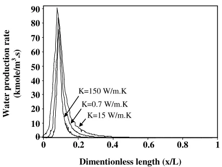
Fig. 6: Water production rate distribution along the central axis of combustion chamber with different wall heat conductivity.
to the other regions. This can help the preheating of reactant gas as well as improving the ignition and flame stability.
As far as water is the product of hydrogen-air combustion, more water production rate along the rector has been used as a criterion to show the quality of reaction progress. Therefore, the water production has been used to judge about combustion performance. In order to illustrate to opposite roles of wall conductivity, water production rate along the combustor for three wall conductivities are studied. Fig. 6 reveals that the water production rate for k=15 W/m.K is more than those of thermal conductivities of 0.7 and 150. In the other words, the figure implies that the water production rate has higher value at a moderate value of wall conductivity. It can be explained by the fact that higher wall conductivity reduces the flame temperature. In addition, this has an advantage of more efficient inlet gas preheating.
As a complementary study, some quantitative predicted temperatures from micro combustors with different wall thermal conductivity are shown in Table 4. As can be seen in this table, as the heat conductivity of combustor wall increased, the exit gas temperature increased and both the flame temperature and the average temperature of combustor decreased.
A similar results were previously reported by Norton & Vlachos [1,2]. They investigated the effect of wall heat conductivity in micro combustion systems with propane-air as well as methane-air mixtures. They studied the positive and negative effects of wall heat conductivity on flame stability and found that a moderate value of
K
a). K=150 W/m/K
b). K=15 W/m/K
c). K=0.7 W/m/K
K=15 W/m.K K=0.7 W/m.K K=150 W/m.K
0 0.2 0.4 0.6 0.8 1
Dimentionless length (x/L) 90
80
70
60
50
40
30 20
10 0
Wa
te
r
p
ro
d
u
ct
io
n
r
a
te
(k
m
o
le
/m
3 .s
0 250 500 750 1000 1250 1500 1750 2000 2250 2500
0 1 2 3 4 5 6 7
Length(mm )
T
e
m
p
e
ra
tu
re
(K
)
One - Two -
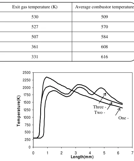
Three - Table 4: Predicted temperatures at various wall heat conductivity.
Wall heat conductivity (W/m/K) Flame temperature (K) Exit gas temperature (K) Average combustor temperature
400 1769 530 509
200 1776 527 570
15 1785 507 584
0.7 1836 361 608
0.2 1861 331 616
heat conductivity is suitable for having a stable flame with low heat loss.
Effect of splitting the hydrogen feed
As was illustrated before, the heat of combustion from reaction between hydrogen and oxygen caused high temperature zone close to the inlet nozzle. This usually causes undesirable effects such as considerable heat losses from chamber, radical destructions and temperature increases more than the allowable temperature of combustor's wall. In order to overcome this problem and reach to a more uniform temperature distribution, the hydrogen has been entered into the chamber in two and three portions with aim of minimizing the formation of hot entrance zone. The total hydrogen flow rate was set at a fixed value for all cases. For the cases of two and three injection stages, the total of hydrogen divided in two and three equal portions and injected to reactor with an angle of 90 .In all cases a chamber inlet diameter of 0.42mm, convection heat transfer coefficient of 50W/m2.K, inlet velocity of 6m/s and the ambient temperature of 300 K were chosen. The temperature profile along the chamber at different layout of fuel injection is shown in Fig. 7. As can be seen in one stage layout, which the whole of fuel is entered via the inlet nozzle, the temperature rises to a maximum temperature, 2340 K, sharply. Consequently, due to heat loss from the wall, the temperature of outlet hot gas is 1310K. In second layout, which the hydrogen is divided into two parts (the first half initially with the feed and the second half in the middle of the combustor), the temperature profile inside the combustor is completely different. The figure shows that the maximum temperature in two stage layout is almost 250K lower than that of first layout. In addition, the predicted results show that the outlet temperature is 120 K higher than that of first layout. Finally, in the third layout there are three temperature peaks with lower values compared two other layout.
Fig. 7: The temperature inside the combustor with different layout.
In this layout, the temperature profile is more uniform and the outlet temperature is 140 K higher than the first layout. Therefore, it can be concluded that with more distributing of hydrogen feed it is possible to reach a more efficient system.
In summary, the above mentioned results reveal that the distribution of feed along the combustor can be a good strategy for controlling the hotspot appeared at the entrance of the reactor as well as having more uniform temperature profile along the combustor. This is also can be quite important for preventing wall damage as well as safety of a combustor. This is in agreement with the results obtained by Barrio et al. [36]. They found that split of feed along a catalytic reactor allowed a noticeable decrease of the maximum temperature in the reactor.
CONCLUSIONS
combustors with inlet diameters of 0.42, 0.22 and 0.12 mm have been modeled. The numerical results indicate that the flame temperature is lower for the smaller combustor. This has been explained by the fact that as the combustion chamber size decreases, the ratio of surface area to volume increases. Consequently, heat loss from the wall of chamber is increased, which affect on flame temperature. In this study, it has been showed that a moderated feed flow rate is required for a stable power generation in micro combustors. When feed flow rate is too low, the performance of the combustor is limited by flame quenching in the chamber. However, at high mass flow rates of fuel-air, the inlet gas mixture have not enough time for reaction and flame may be blown out, which also leads to low combustion efficiency. The results of this study reveal that the wall thermal conductivity is another parameter which plays an important role in the performance of micro combustor. The results show that lower wall heat conductivity can reduces the heat loss from the system and causes a stable combustion. On the contrary, the higher heat conductivity can increases preheating of reactants and decreasing wall thermal stress. From this investigation, it can be concluded that the split of hydrogen feed along the combustor allowed a noticeable decrease in maximum temperature of the combustion chamber. The hydrogen feed splitting can causes a more uniform temperature to be established in the chamber. Finally, it can be concluded that by CFD modeling of combustion of premixed hydrogen-air mixture in a micro scaled chamber, it is possible to design an efficient system without need to many expensive experimental analysis.
Acknowledgment
The authors wish to express their thanks to the Renewable Energy Organization of Iran, for supporting of this work.
Nomenclature
Cp Specific heat capacity, kJ/kg⋅K D Inlet diameter of combustor, m Eij Linear deformation rate, s-1 H Heat transfer coefficient, W/m2⋅K L Combustor length, m x Distance from the inlet in central axis, m K Thermal conductivity, W/m⋅K T Temperature, K
u Velocity vector, m s-1 u, ui, uj Mean velocity components, m s-1 xi, xj Cartesian coordinate, m
Greek symbols
Equivalence ratio
eff
τ Stress tensor, Pa
µ, µT, µeff Laminar, turbulent and effective viscosity, Pa s
ν Kinematic viscosity, m2/s
ρ Density, kg m-3
Received : Jan. 1, 2010 ; Accepted : Jan. 17, 2011
REFERENCES
[1] Norton D.G., Vlachos D.G., Combustion Characteristics and Flame Stability at the Microscale: a CFD Study of Premixed Methane-Air Mixtures, Chem. Eng. Sci., 58, p. 4871 (2003). [2] Norton D.G., Vlachos D.G., A CFD Study of
Propane-Air Microflame Stability, Combust. Flame.,
138, p. 97 (2004).
[3] Yang W.M., Chou S.K., Shu C., Li Z.W., Xue H., Combustion in Micro Cylindrical Combustors with and Without a Backward Facing step, Appl. Therm. Eng., 22, p. 1777 (2002).
[4] Karagiannidis S., Mantzaras J., Jackson G., Boulouchos K., Hetero-homogeneous Combustion and Stability Maps in Methane-Fueled Catalytic Micro Reactors, Proc. Combust. Inst., 31, p. 3309 (2007). [5] Li J., Chou S.K., Huang G., Yang W.M., Li Z.W.,
Study on Premixed Combustion in Cylindrical Micro Combustors: Transient Flame Behavior and Wall Heat Flux, Exp. Therm. Fluid. Sci., 33, p. 764 (2009).
[6] Li J., Chou S.K., Li Z.W., Yang W.M., Experimental Investigation of Porous Media Combustion in a Planar Micro Combustor, Fuel, 89, p. 708 (2010). [7] Cao H.L., Xu J.L., Thermal Performance of a Micro
Combustor for Micro Gas Turbine System, Energy Conv. Manag., 48, 1569 (2007).
[9] Miesse C., Masel R., Short M., Shannon M., Experimental Observations of Methane-Oxygen Diffusion Flame Structure in a Sub-Millimeter Microburner, Combust. Theory Model., 9, p.77 (2005). [10] Junwei L., Beijing Z., Experimental Investigation on
Heat Loss and Combustion in Methane-Oxygen Micro Tube Combustor, Appl. Therm. Eng., 28, p. 707 (2008).
[11] Choi H.S., Park T.S., Suzuki K., Turbulent Mixing of a Passive Scalar in Confined Multiple Jet Flows of a Micro Combustor, Int. J. Heat Mass Transfer,
51, p. 4276 (2008).
[12] Zhou J., Wang Y., Yang W., Liu J., Wang Z., Cen K., Improvement of Micro Combustion Stability Through Electrical Heating, Appl. Therm. Eng., 29, p. 2373 (2009).
[13] Kim K.B., Kwon O.C., Studies on a Two-Staged Micro Combustor for a Micro Reformer Integrated with a Micro Evaporator, J. Power Sourc., 182, p. 609 (2008).
[14] Raimondeau S., Norton D., Vlachos D.G., Masel R.I., Modeling of High Temperature Micro Burners, Proc. Combust. Inst., 29, p. 901 (2002).
[15] Leach T.T., Cadou C.P., Jackson G.S., Effects of Structure Conduction and Heat Loss on Combustion in Micro Channels, Combust. Theory Model., 10, p. 85 (2006).
[16] Jejurkar S.Y., Mishra D.P., Numerical Characterization of a Premixed Flame Based Annular Micro Combustor, Int. J. hydrogen energy, 35, p. 9755 (2010).
[17] Zhou J., Wang Y., Yang W., Liu J., Wang Z., Cen K., Combustion of Hydrogen-Air in Catalytic Micro Combustors Made of Different Material, Int. J. hydrogen energy, 34, p. 3535 (2009).
[18] Kaisare N.S., Vlachos D.G., Optimal Reactor Dimensions for Homogeneous Combustion in Small Channels, Catal. Today, 120, p. 96 (2007).
[19] Li J., Chou S. K., Li Z., Yang W., Development of 1D Model for the Analysis of Heat Transport in Cylindrical Micro Combustors , Appl. Therm. Eng.,
29, p. 1854 (2009).
[20] Li Z.W., Chou S.K., Shu C., Yang W.M., Predicting the Temperature of a Premixed Flame in a Micro Combustor, J. Appl. Physic., 96, p. 3524 (2004). [21] Li Z.W., Chou S.K., Shu C., Yang W.M., Entropy
Generation During Micro Combustion, J. Appl. Physic., 97, p. 84914 (2005).
[22] Chen G., Chen C., Wu C., Chao Y., Effects of Catalytic Walls on Hydrogen-Air Combustion Inside a Micro Tube, Appl. Catal., 332, p. 89 (2007). [23] Leach T.T., Cadou C.P., The Role of Structural Heat
Exchange and Heat Loss in the Design of Efficient Silicon Micro Combustors, Proc. Combust. Inst., 30, p. 2437 (2005).
[24] Benedetto A.D., Sarli V.D., Russo G., A Novel Catalytic-Homogenous Micro Combustor, Catal. Today, 147S, p. S156 (2009).
[25] Benedetto A.D., Sarli V.D., Russo G., Effect of Geometry on the Thermal Behavior of Catalytic Micro Combustors, Catal. Today, 155, p. 116 (2010).
[26] Maruta K., Takeda K., Ahn J., Borer K., Sitzki L., Ronney P.D., Deutschmann O., Extinction Limits of Catalytic Combustion in Micro Channels, Proc. Combust. Inst. 29, p. 957 (2002).
[27] Norton D.G., Wetzel E.D., Vlachos D.G., Thermal Management in Catalytic Micro-Reactors, Ind. Eng. Chem. Res., 45, p. 76 (2006).
[28] Hua J., Wu M., Kumar K., Numerical Simulation of the Combustion of Hydrogen-Air Mixture in Micro-Scaled Chambers. Part I: Fundamental Study, Chem. Eng. Sci., 60, p. 3497 (2005).
[29] Shi L., Bayless D.J., Prudich M., A Model of Steam Reforming of Iso-Octane: The Effect of Thermal Boundary Conditions on Hydrogen Production and Reactor Temperature, Int. J. hydrogen energy, 33, p. 4577 (2008).
[30] Fluent 6.2®: Fluent Inc., Lebanon, NH, USA, (2005).
[31] Andrae J.C.G., Bjornbom P.H., Wall Effects of Laminar Hydrogen Flames Over Platinum and Inert Surfaces, American Inst. Chem. Eng. J., 46, p. 1454 (2000).
[32] Giovangigli V., Smooke M.D., Extinction of Strained Premixed Laminar Flames with Complex Chemistry, Combust. Sci. Tech., 53, p. 23 (1987).
[33] Glassman I., Yetter R. A., "Combustion", 4th Ed, Chap 1, p. 30, Academic Press, California, (2008). [34] Li J., Chou S.K., Yang W.M., Li Z.W., A Numerical
[35] Li J., Chou S. K., Li Z. W., Yang W. M., A Comparative Study of H2-Air Premixed Flame in Micro Combustors with Different Physical and Boundary Conditions, Combust. Theory Model., 12, p. 325 (2008).