© Universiti Tun Hussein Onn Malaysia Publisher’s Office
IJIE
Journal homepage:http://penerbit.uthm.edu.my/ojs/index.php/ijie ISSN : 2229-838X e-ISSN : 2600-7916
The International
Journal of
Integrated
Engineering
Application of Finite Element Modelling to Lightweight
Aggregate (LECA) Column-Raft
Azhani Zukri
1,2,*, Ramli Nazir
2, Kok Shien Ng
3, Khairun Nisa Mat
1Faculty of Civil Engineering and Earth Resources,
Universiti Malaysia Pahang, 26300 Gambang, Pahang, MALAYSIA
2Centre of Tropical Geoengineering, Faculty of Civil Engineering
Universiti Teknologi Malaysia, 81310 Skudai, Johor, MALAYSIA
3Faculty of Civil Engineering,
Universiti Teknologi Mara, 13500 Permatang Pauh, Penang, MALAYSIA
*Corresponding Author
DOI: https://doi.org/10.30880/ijie.2019.11.09.023
Received 21 February 2019; Accepted 16 October 2019; Available online 31 December 2019
Abstract: With the evolution of computer technology, many numerical software such as PLAXIS, FLAC, and ABACUS have been developed to solve complicated geotechnical problems in two or three-dimensional space. Finite element modeling can be easily applied to the treated soft soil with soil replacement or granular raft method, since the computer codes is able to solve complex problems like soil-structure interactions, seepage, and soil dynamic. In addition, the finite element analysis can be conducted rapidly and at relatively low cost. Soil replacement technique is the simplest and the oldest ground improvement method to improve the soft soils underneath light structures by replacing weak soil (e.g. soft clay and organic soils) with more competent materials such as sand, gravel or other suitable granular materials. The behavior of treated soils in terms of settlement and bearing capacity can be analyzed with finite element method. However, finite element analysis requires several preliminary checks to ensure the accuracy of the result. The use of finite element for geotechnical analysis requires consideration of the material model, mesh configuration and boundary conditions, type of analysis depending on objective of the research and time available. This paper focuses on the finite element modelling methodology developed to analyze the behavior of soft clay improved by Lightweight Expanded Clay Aggregate (LECA). LECA is known as common lightweight materials that have been applied successfully in civil engineering works where weight is an issue because by replacing the soft soils with this material, it can help to reduce dead loads and lateral forces by more than half. Mohr-Coulomb constitutive model has been selected to represent the behavior of LECA granular material in numerical analysis. While, the nonlinear behavior of soft soil (Kaolin Clay) is modelled with Soil Hardening constitutive model. In this paper, the validation methods that can be used to verify the numerical analysis is discussed. It is hope that this paper can be a useful guideline for young researcher in performing finite element modelling to simulate foundations supported by lightweight aggregate.
1. Introduction
Numerical analysis using finite element technique is one of the popular modelling approaches in the field of engineering. The finite element method provides a valuable numerical tool for the analysis and design of various geotechnical structures. To date, a variety of finite element computer programs have been developed with a number of useful facilities in order to suit different analysis and needs, such as settlement evaluation, slope stability, stress behaviour and so on. The behaviour of soil is simulated by appropriate stress-strain laws applied to finite elements. The analysis of stone columns in two or three-dimensional space using finite element method is well performed by many researchers [1] is referred extensively in this study.
The selection of suitable constitutive model to represent the actual soft soil behaviour is not simple since soils are complex materials consisting of soil particles and void filled with water and/or air. Hence, it is very important to choose appropriate soil model when running the analysis so that the result produced can predict the actual behaviour of soil. Nowadays, the numerical modelling software is equipped with numerous constitutive models for modelling the stress-strain behaviour of soil starting from simple to more complex model based on analysis needs. In addition to this, several laboratory tests should be done in advance to collect all the important parameters related to compression and shearing behaviour of soils, such as physical tests, triaxial and oedometer test. These parameters are essential for accurate numerical analysis. It should be remembered that no single soil constitutive model is able to accurately simulate all the behaviour of soils under different conditions and applications. During the finite element analysis few concerns are necessary: the geometrical model should be calibrated through sensitivity analysis to select the most appropriate meshes; performing boundary condition checks; determining type of analysis whether it is drained, undrained or consolidation; and performing construction stages.
In recent years, stone column treatments are used beneath large loaded areas, such as embankments, but they are also used beneath footings, when the applied loads are not high [2]. The benefit of stone columns is due to the partial replacement of soft soil by more efficient materials such as stone aggregate, sand and other granular materials. These substitutes also act as reinforcement material, thus increasing stiffness and overall strength of the compressible soil. Several materials such as crushed polypropylene (PP), fly ash, coal bottom ash, recycled aggregate, tyre chips, Pulverized Fuel Ash (PFA), Silica-Manganese slag, quarry dust, stone dust, limestone, river sand, etc. have all been recognized to be utilized as stone column materials replacing its traditional aggregate materials. Nonetheless, no study or research has been found with respect to the usage of LECA materials to be used as stone column backfills [3].
1.1 Geometrical Model
As stated by Canizal et al. [4], there are five main approaches for modelling stone columns numerically [4]; unit cell approach, plane strain method, axial symmetry technique, homogenization technique and 3D model. The first four approaches are considered as the two-dimensional (2D) analyses. Many numerical studies have utilized the axisymmetric model for the unit cell model of uniformly loaded stone column groups or plane strain models. However, the best way to represent the real conditions of soft soil behavior is through a three-dimensional modelling. Table 1 below summarize the suitability of some of these models to study on improvement of soft soil stabilized with stone column.
Table 1 – Suitability of simplifies geometrical models to study different features of stone column treatment [5]
Model Settlement Consolidation Stability
Unit cell Completely Completely Not suitable Stone
h Moderatei bl Moderatei bl Moderatei bl Homogenizati
on 3D
Moderate suitable
C l l
Slightly suitable
C l l
Slightly suitable
C l l
1.2 Model selection
to the lack of restraint with columns subject to deformation at lower stress levels than those in infinite arrays. Hence, column at the edge of the group won’t be analysed due to this complexity.
The other task is to know how accurate the results from the numerical modelling correspond to what is happening in the field and actual soil behaviour. Therefore, the analysis needs a further step for the verification and validation purposes. Verification is to certify that the computer model has been developed correctly, meanwhile validation is to ensure that the model can fulfils the usage. From the review, the numerical modelling can be validated using other numerical methods, analytical solution using established methods, experimental work or physical modelling, an actual case study and full-scale or field tests [1]. The first two validation methods are simpler, faster and more economical than physical modelling and the full-scale tests. However, physical modelling and full-scale testing can provide even more accurate verification though not economical and require more time to perform testing.
For example, Morteza Esmaeili & Seyed Mehrab Hakimpour [7], Kongpop Watcharasawe et al. [8], Sexton & McCabe [9], Martin Gab & Helmut Schweiger [10], Muntohar et. al. [11] and Sexton et al. [12] have conducted the full-scale testing or field test to validate the numerical analysis that have been done. While analytical method has been chosen by Basim Jabbar Abbas [13] and Micheál Killeena & Bryan Cabeb [14]. In addition to that, Elwakil & Azzam [15], Radhika [16], Mohammadreza Jaberi Nasab [17] and Shaymaa Kadhim [18] established some experimental or physical modelling work in the laboratory for validation purpose. Some other studies too were conducted to utilise the three-dimensional numerical software and later validated through experimental works, analytical analysis or compared them to the actual case studies or otherwise by Hasan et al. [19], Hasan & Samadhiya [20], Weber & Springman [21], Sreechithra & Niranjana [22], Muzammil et al. [23], Tandel et al. [24] and Keykhosropur et al. [25].
2. Methodology and Procedures
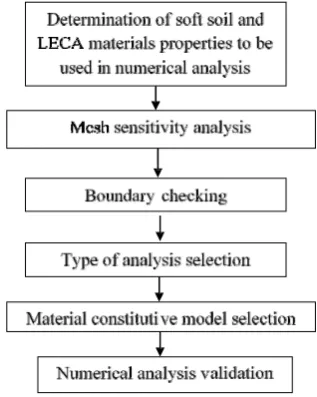
A finite element analysis was performed using a commercial software Plaxis 3D (2016). Preliminary checks were done to ensure the accuracy of numerical analyses conducted. The use of finite element for geotechnical analysis requires consideration of the material model, mesh configuration and boundary conditions, type of analysis depending on time available and targeted findings in the study. Fig. 1 represents the methodology flowchart for the numerical procedure utilized in the study.
Fig. 1 - Numerical procedures flowchart
For the stress pressure on the loading platform, it can be calculated from 2.5m height embankment with 20kN/m3
unit weight of filling material, which is 20 x 2.5 = 50kN/m2. In addition to that the typical working load on a stone
column foundation would be in the range of 25kN/m² to 50kN/m². Therefore, a vertical pressure of 50 kN/m2 is
imposed on the raft, as a distributed load. The detail geometrical of model as shows in Fig. 2.
2.1 Material properties
in the stone column, and used to reinforce the soft clay (kaolin). From Unified Soil Classification System (USCS), LECA can be classified as well graded where the criteria Cu > 4 & 1 < Cc < 3 has been met [26]. Loose bulk density for LECA determined is 266 kg/m3 while rodded bulk density calculated is 293 kg/m3, which is shows that 10%
volume reduction by compaction. Internal friction angle of LECA determined in this study is 35.
Fig. 2 - Detail geometrical of model
2.2 Mesh sensitivity analysis
In Plaxis 3D a full generation of finite element meshes can be done automatically, depending on the soil stratigraphy, all structural objects or foundation configurations, loads and boundary conditions. The mesh should be sufficiently fine to acquire accurate numerical results, however, very fine meshes need to be avoided if possible since it will lead to excessive calculation times. The soft-ware uses 10 nodded tetrahedral elements for basic soil elements, while special types of elements are used to model structural behavior. For example, 3-nodes elements are used for beams, which are compatible with the 3-nodes edges of a soil elements, 6-nodes for plate and 12-nodes elements are used to simulate the behavior of soil-structure interaction. The number of elements in a mesh is dependent upon the degree of mesh coarseness selected which can be varied from very coarse to very fine. Mesh sensitivity analysis was conducted for circular foundations with configurations of dimensions the same as those used in this research. The displacement below the foundation is of key interest in this research as the settlement of stone columns is of primary concern and the accuracy of the mesh will influence the settlement prediction. A flowchart outlining the steps taken to ensure accurate numerical analyses is shown in Fig. 3.
Fig. 3 - Mesh sensitivity analysis flowchart
stone column foundation being in the range of 25kN/m² to 50kN/m², to save on computational time. Mesh sensitivity analyses were conducted for four different foundation sizes where the accuracy of medium and fine meshes are compared against very fine (vf) meshes. The displacement (u) was measured at three different points A, B and C which
are 0, 1 and 2 m below the center of foundation, respectively. The accuracy of medium and fine meshes is determined by comparing the normalized error for displacement against very fine meshes (refer Eq. (1)).
(1)
2.3 Influence of Distance to Boundary
The foundation modelled in the subsequent parametric studies is surrounded by a zone of soil, which undergoes no lateral displacement along its outer boundary. Therefore, it is necessary to allocate the boundary at a sufficient distance from the centre of foundation so that boundary conditions do not influence the numerical results. Killeen (2012) suggested that a foundation width of eight times the breadth for a foundation of 3 meters will neglected the influence of the outer boundary. The sensitive analysis conducted by Stuart Law (2015) proved that this suggestion obtained a valid result.
2.4 Type of Analysis
The long term behaviour of cohesive soils, which develop excess pore pressure during loading, can be modelled by two methods with PLAXIS 3D: (i) Undrained loading followed by consolidation analysis, and (ii) Drained analysis. The first method provides a closer simulation of reality than the second method. However, it needs longer time to complete the analysis. The soil is specified to behave in an undrained manner during the application of loads. Initial undrained settlements were computed and long-term analysis are then determined by conducting a consolidation scheme. The soil can be defined using either total or effective strength parameters for this method. However, it is not possible to capture the increase of soil shear strength with consolidation or the stress dependency of soil stiffness when the total strength parameters used in the analysis. Therefore, the effective strength parameters were used in all the subsequent numerical analysis such as E’, c’ v’ and φ’.
The behaviour of the soil is defined using effective strength and stiffness parameters. However, it is not possible to separate the settlements from the initial undrained response and primary consolidation. For the purposes of comparing, the consistency analysis of both models has been conducted by M. Killeen (2012) and concluded that drained analysis method predicts slightly higher settlement improvement factors for footings supported by 9 columns, while the contradicting findings was observed for the footing supported by 5 columns. Nevertheless, both methods predicted a similar variation of settlement improvement factor with column length for all the different configurations of columns, where the maximum normalised error is less than 7% [27]. Similar type of analysis has been used by several researcher to simulate the stone column behaviour in order to shorten the duration of the analysis. Therefore, to simulate long term soil behaviour without the need to model precise history of undrained loading and consolidation and also to permit timely analysis in this research, drained analysis is adopted to reduce computational time and to allow for a greater number of sensitivity and parametric analysis to be done.
2.5 Modelling of Column-Soil Interface
Interface elements are available in PLAXIS 3D to model the interaction between smooth and rough surfaces i.e. between piles/basement walls and soil. Interface elements can simulate gap and slip displacements which are normal and parallel to the interface, respectively. The element behaviour is modelled as elastic-plastic, with the Coulomb criterion adopted to distinguish between elastic and plastic behaviour. The loss of strength at the interface is modelled with a strength reduction factor (Rinter), which relates the interface strength to the soil strength through friction angle
cohesion. In accordance with standard practice for numerical modelling of stone columns, Noura et al. (2016) and Shahu & Reddy (2011) suggested column-soil interface elements are not used [28], [29]. Stuart Law (2015) concluded that the use of interfaces caused the over prediction of settlement and therefore an interface free approach was adopted [6]. In addition, Balaam et al. (1985) and Killeen (2012) examined the effect of interfaces and found similar results [27], [30]. However, in this study the stone columns are assumed to be ‘wish in place’, where possible smear effects caused by disturbance on the surrounding soil due to column installation effect is neglected. Therefore, strength reduction factor (Rinter) is assumed to be 1.
2.6 Selection of Constitutive Model
3D software has comes up with 8 constitutive models for different conditions and type of soil analysis. So that, the engineers should choose 'right' constitutive model which provides a reasonable fit to data obtained from laboratory tests [1]. Linear elastic model for example, considers a material as an idealized linear-elastic material which excludes any plastic deformation, preventing the development of irreversible strains during loading and unloading. The model is simple and only requires two parameters; Young's elastic modulus, E and Poisson's ratio, ν. In addition, Mohr-Coulomb model is more convenient and readily useable with field and laboratory data. This model is applicable to analyze the stability of dams, slopes, embankments and shallow foundations [31].
In order to select the right constitutive model, several famous models have been selected for analysis in this study. The selection of model made based on availability of soft soil and LECA parameters. While the non-existent parameters were calculated based on correlation or indirectly calculated using others suitable parameters, and these particular matters readily available in Plaxis 3D. The results obtained from the analysis were compared to analytical calculation. For replacement method, the Terzaghy’s Equation has been adopted for analytical analysis. The models selected for analysis are; Mohr-Coulomb Model (MC), Linear Elastic Model (LE), Soft Soil Model (SSM), Soil Hardening Model (SHM) and Soft Soil Creep Model (SSC).
3. Results and Discussion
Lightweight aggregate is the generic name of a group of aggregates having a relative density lower than normal aggregates (natural sand, gravel, and crushed stone), sometimes is referred to as low density aggregate. Depending on the source and the method of production, lightweight aggregates exhibit considerable differences in particle shape, texture and properties. The properties of LECA shows that it can be used for replacing natural aggregates in many civil engineering works. LECA has specific properties which can be applied as a suitable material in structural and geotechnical application. In terms of stress-strain behavior, the material can be considered as a work hardening (negative dilation) material despite the very low confining pressures applied. In addition, for simplicity Mohr-Coulomb constitutive model also can be used to represent the behavior of LECA granular material in numerical analysis.
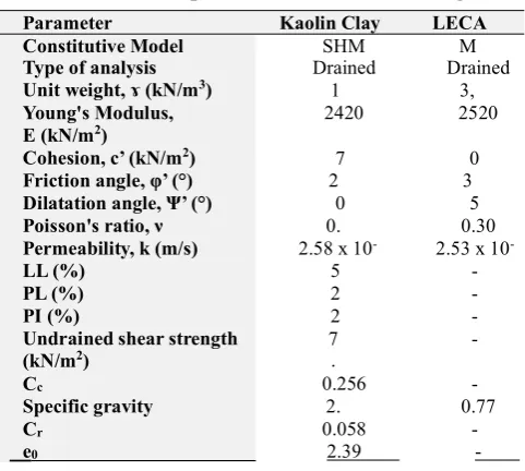
While the nonlinear behavior of soft soil (Kaolin Clay) is modelled with Soil Hardening constitutive model. The models have proven applications in the modelling of stone columns including large arrays of columns [32]. Also, this model has been adopted by many researchers to simulate the soft clay behavior. The material parameters used in the analysis are summarized in Table 2.
Table 2 - Soil parameters used in modelling
Parameter Kaolin Clay LECA
Constitutive Model SHM M
Type of analysis Drained Drained
Unit weight, ɤ (kN/m3) 1 3,
Young's Modulus,
E (kN/m2) 2420 2520
Cohesion, c’ (kN/m2) 7 0
Friction angle, φ’ (°) 2 3
Dilatation angle, Ψ’ (°) 0 5
Poisson's ratio, ν 0. 0.30
Permeability, k (m/s) 2.58 x 10- 2.53 x 10
-LL (%) 5
-PL (%) 2
-PI (%) 2
-Undrained shear strength
(kN/m2) 7.
-Cc 0.256
-Specific gravity 2. 0.77
Cr 0.058
-e0 2.39
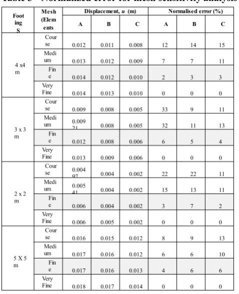
-The normalized error for the displacement and mean effective stress for circular footing are as shown in Table 3. It shows that the values for medium and fine meshes are converging towards the very fine mesh and also that the normalized error between the fine and very fine meshes for the displacement and mean effective stress is quite low (maximum error is less than 10%) and considered acceptable. Therefore, the fine mesh is more appropriate to be selected for finite element analysis.
A sensitivity analysis was conducted on a 1.5 meter square footing, where the distance to the boundary from the footing center ranged from 2B to 12B, where B is width of footing. The footing was loaded to 25 kN/m2 and the
Distan ce to boun
Point
inte re st Displace ment
Normali se d e rror
2 B
A 0.062
-31.91%
B 0.028
-33.33%
C 0.009
-12.50%
3 B
A
0.069 -46.81%
B
0.030 -42.86%
C
0.008 0.00%
4 B
A 0.071
-51.06%
B 0.028
-33.33%
C 0.007 12.50%
5 B
A 0.069
-46.81%
B 0.027
-28.57%
C 0.007 12.50%
6 B
A 0.056
-19.15%
B 0.023 -9.52%
C 0.007 12.50%
8 B
A 0.047 0.00% B 0.021 0.00% C 0.008 0.00%
1 2 B
A 0.047
-B 0.021
-C 0.008
-below the foundation. The distance to boundary that can be selected for further analysis is eight times the largest foundation dimension (8B) measured from center of foundation.
Table 3 - Normalized error for mesh sensitivity analysis Table 4 - Normalized error for boundary analysis
Foot ing S Mesh (Elem ents
Displacement,u(m) Normalised error (%)
A B C A B C
4 x4 m
Cour
se 0.012 0.011 0.008 12 14 15 Medi
um 0.013 0.012 0.009 7 7 11 Fin
e 0.014 0.012 0.010 2 3 3
Very
Fine 0.014 0.013 0.010 0 0 0
3 x 3 m
Cour
se 0.009 0.008 0.005 33 9 11 Medi
um 0.00921 0.008 0.005 32 11 13 Fin
e 0.012 0.008 0.006 6 5 4
Very
Fine 0.013 0.009 0.006 0 0 0
2 x 2 m
Cour se 0.004
97 0.004 0.002 22 22 11 Medi
um 0.005
41 0.004 0.002 15 13 11 Fin
e 0.006 0.004 0.002 3 7 2
Very
Fine 0.006 0.005 0.002 0 0 0
5 X 5 m
Cour
se 0.016 0.015 0.012 8 9 13 Medi
um 0.017 0.016 0.012 6 6 10 Fin
e 0.017 0.016 0.013 4 6 6
Very
Fine 0.018 0.017 0.014 0 0 0
3.1 Comparison of Constitutive Models (Sensitivity Analysis)
Consolidation settlement magnitude can be predicted using analytical method of one-dimensional Terzahgy’s Equation. Immediate Settlements and settlements due to primary consolidation occur during construction. Bowles suggests that immediate settlements are those that take place within 7 days of loading [33]. Meanwhile settlements due to secondary consolidation and creep occur after the end of construction. However, only primary consolidation settlement was calculated since, the immediate settlement is insignificant in clay and can be ignored, while secondary consolidation settlement is more important in highly compressibility clay and organic soils such as peat. In over consolidated clay, the secondary compression index is very small, of less practical importance (Braja M Das) [34].
The selection of model made based on availability of soft soil and LECA parameters. While the non-existent parameters was calculated based on correlation or indirectly calculated using others suitable parameters, and this particular matters readily available in Plaxis 3D. The results obtained from the analysis were compared to analytical calculation. For replacement method, the Terzaghy’s Equation has been adopted for analytical analysis. The models selected for analysis are; Mohr-Columb Model (MC), Linear Elastic Model (LE), Soft Soil Model (SS), Soil Hardening Model (SHM) and Soft Soil Creep Model (SSC). For untreated soil, the settlement magnitude calculated is 0.3153 m (for 50kN/m2 uniform load) while Plaxis 3D provided a result slightly higher, as predicted by SS model, while MC
4. Validation Process
A major problem was to identify how accurate was the results from the numerical modelling corresponding to what is happening in the field and the actual soil behavior. Therefore, the analysis needs further step for the verification and validation purposes. Verification is to certify that the computer model has been developed correctly, while validation is to ensure that the model fulfils its use. From the review, the numerical modelling can be validated using other numerical methods, analytical solution using established methods, experimental work or physical modelling, an actual case study and full-scale or field tests. The first two validation methods are simpler, faster and more economical than physical modelling and full-scale tests. However, physical modelling and full-scale testing can provide even more accurate verification though not economical and require more time to perform testing.
4.1 Validation with Analytical Methods
Many established analytical solutions could be used to estimate the settlement of stone column. Most of the methods basically derived from unit cell idealization whereby, stone column is modelled to be a concentric body in a composite soil mass (single pile-soil unit) and that the boundary conditions are rigid such that the sides of the unit cell are free from radial displacements and shear stresses. The equilibrium approach or stress reduction method was proposed by Aboshi et al. (1979) and Barksdale and Bachus (1983) in the estimation of settlement of composite ground. In this approach, the stress concentration ratio, n, is predetermined empirically. By adopting a 'unit cell' assumption, the method estimates settlement reduction due to stone column installation by using one dimensional consolidation theory, where the settlement is considered only in the vertical direction [6]. A settlement reduction ratio, β, can be calculated which is the ratio of improved to unimproved soil by considering the stress concentration ratio. Barksdale and Bachus (1983) developed an empirical design chart to determine the stress concentration ratio. Using the equation developed, the stress concentration ratio determined was 1.10 which meet the typical stress concentration ratio under embankment loading which is ranging from 1 to 2; however, for granular columns under rigid loading the stress concentration ratio ranges from 2 to 4.
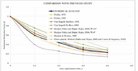
Priebe (1976) proposed a method for assessing settlement reduction based on the unit cell, elastic theory and Rankine earth pressure theory where the stone column is assumed to be incompressible and surrounded by an elastic material. A series of design curves has been generated where the basic settlement improvement factor was plotted against the area ratio for a range of granular materials. Priebe (1995) considered the effect of compressibility of the column material and the overburden pressure, where the design charts to calculate the settlement of single and strip footing reinforced by a limited number of stone columns has been developed. Pulko and Majes (2005) and Castro and Sagaseta (2009) proposed the methods to calculate the settlement of the granular column-reinforced soft foundation based on elastic-plastic constitutive models, where the soft soil is assumed to be linearly elastic while the granular columns are assumed to be linearly elastic–perfectly plastic following the Mohr–Coulomb failure criterion with a constant dilatancy angle. This Elasto-plastic method provides the most complete closed-form analysis, however, it becomes more complicated to be used in practice.
A parametric study was conducted to examine the influence of key parameters on the settlement improvement factors for floating stone columns. Based on the parametric study, Ng and Tan proposed a new design equation for stone column reinforced grounds [35]. Ng and Tan then introduced a new mechanical method to account for optimum length and the yielding effect in the plastic zone. The method can be utilized to predict the settlement performance of a footing on a limited number of stone columns (floating and end bearing system) for homogenous and non-homogenous ground condition [36]. A simplified solution and design chart were proposed by Ng to calculate the settlement ratio for floating stone columns. The study has been conducted using 2D finite element analysis with the influence of different key parameters such as column length, area replacement ratio, loading intensity and post installation lateral earth pressure on the settlement ratio. Design chart developed from this study was validated by a case study where a reasonable agreement was obtained [37]. The comparison of numerical analysis in this study has been made with the analytical solution that has been established before as presented in Fig. 5 below. The comparison of settlement reduction factors, β and the corresponding area replacement ratios with some published field test results and observations is shown in Fig. 4.
single and a group of stone columns [40]. The equation was obtained by carrying out statistical analysis using the SPSS (Statistical Package for the Social Sciences) program from the experimental work and previously studied data.
Fig. 4- Comparison of settlement reduction factors,βand corresponding area replacement ratios
(2)
where, cu is the soil undrained shear strength in kPa, As is the area replacement ratio, Ns is stone columns number, and L/D is length to diameter ratio. This method has been used to analytically predict the bearing capacity of LECA column and as a comparison to numerical as well as physical modelling results conducted in this study.
4.2 Validation with Physical Methods
In this study the physical modelling was verified using numerical analysis. The main advantage of physical modelling is that it permits the parametric studies to be performed including the model geometry, different types or combinations of loading and soil conditions concurrently [41]–[43]. Physical modelling in laboratory scale is also one of the options used method to validate the analytical approach. The method can provide even more accurate verification, economical and require less time to perform compare to field testing and full-scale model. Small scale physical modelling could be developed to complete the verification procedure for numerical analysis. The great advantages of the small-scale model is that all the detail of model such as material, loading, drainage and boundary conditions can be controlled. It requires small quantities, short durations test, huge number of test and repeating observations, varying key parameters and economical. If the model is not constructed in a full scale the observation should be made at model scale to the prototype scale to reduce an error in this process. There are two approaches whereby error in physical modelling can be reduced; Modelling of Models and Modelling of Prototypes. Modelling of models approach was selected in this study due to cost limitation. For a model scale experiment to give a valuable representation of the prototype, all the major factors influencing the fundamental soil and fluid mechanics must be in proportion between the prototype and model, while the factors which are not in proportion must have a negligible influence on the fluid mechanical behavior. For reduction of parameters to be monitored during model tests, dimensional analysis may be used as a guideline (refer Wood 2004, and Shahu and Reddy 2011). If dimensions are reduced but not the particle sizes and properties of constituent materials, then this will create distortion in the model and the model behavior may no longer represent the prototype behavior [44].
4.3 Scaling Factor
4.4 Validation Result
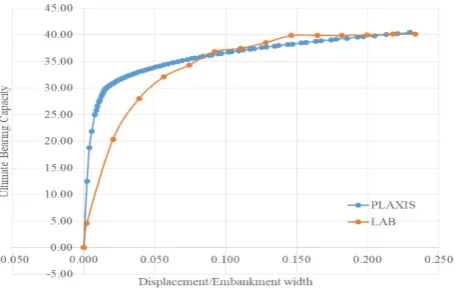
From the physical modelling test, the results will be compared with the numerical value recorded. Fig. 5 compares the ultimate bearing capacity of untreated soil from numerical analysis and experimental test. The untreated condition was considered as controlled model and used as a reference here. From the analysis, it is found that the numerical results are closed to analytical method as well as the experimental results where the percentage of error is less than 30%. It is confirmed that the constitutive model and the type of analysis selected in finite element modelling are convenient to use for LECA column-raft behavior prediction. In addition, analytical equations and physical modelling conducted were successfully validated the findings recorded from finite element analysis.
Fig. 5- Comparison results for untreated soil condition
Table 5 tabulates the comparison of ultimate bearing capacity and settlement calculated using analytical equations, numerical analysis through Plaxis software and physical modelling results from the laboratory.
Table 5 - Results comparison
Sample condition Behaviour Analytic La Plaxi %
Untreated Ultimate bearing capacity 38.62 38.5 38.1 0.91
Settlement (mm) 315.3 343. 320. 6.58
0.15Hs LECA replacement Ultimate bearing capacity 58.08 60.6 65.6 8.16
Settlement (mm) 267.5 213. 189. 10.8
0.15Hs LECA replacement + Ultimate bearing capacity 61.75 61.7 56.6 8.25
Settlement (mm) 224.85 208.5 227.74 9.23
5. Summary
Finite element method is one of the reliable tools to analyze the performance of ground improvement. Many established commercial software has been developed for this purpose. However, finite element analysis requires several preliminary checking to ensure the accuracy of the result. In addition, the results provided from numerical software should be validated in order to verify the accuracy of the value recorded. The proposed methodology to analyze settlement behavior of soft clay improved by Lightweight Expanded Clay Aggregate (LECA) used as a granular material replacing normal aggregates in column-raft can be summarized as following:
• Mesh sensitivity analyses shows that the fine mesh is more appropriate to be selected for finite element analysis. • LECA has a very specific property which can be included as a suitable material in geotechnical application. The
material can be considered as a work hardening (negative dilation) material however, Mohr-Coulomb model is more convenient and readily useable with field and laboratory data.
• Compared to other models, Soft Hardening Model estimated value closed to analytical value where the percentage was less than 2%, therefore, Soil Hardening Model is appropriate to represent the behavior of soft soil in this study. • To permit timely analysis in this research and to simulate long term soil behavior, drained analysis was adopted to
allow for a greater number of sensitivity and parametric analysis was done.
• Possible smear effects caused by disturbance on the surrounding soil due to column installation effect can be neglected, where the strength reduction factor, Rintervalue is assumed to be 1.
• The numerical modelling can be validated using other numerical methods or software developed, analytical solution using established methods, experimental work or physical modelling, an actual case study and full-scale model or field tests.
• The analytical method is found to be the simplest and easiest way that can be used to validate the numerical results. • The physical modelling method provide more accurate verification, economical and required less time to perform
Acknowledgement
The authors wish to thank the technical support received from the Universiti Teknologi Malaysia and Universiti Teknologi MARA, Pulau Pinang for providing facilities during the research work
References
[1] A. Zukri and R. Nazir, “Numerical modelling techniques of soft soil improvement via stone columns: A brief review,”IOP Conference Series: Materials Science and Engineering, vol. 342, no. 1, p. 12002, 2018.
[2] K. S. Watts, D. Johnson, L. A. Wood, and A. Saadi, “An instrumented trial of vibro ground treatment supporting strip foundations in a variable fill,”Géotechnique, vol. 50, no. 6, pp. 699–708, 2000.
[3] A. Zukri and R. Nazir, “The Sustainable Materials Used As Stone Column Filler: A Short Review,”iCITES2018, 2018.
[4] J. C. J. Canizal A. Cimentada, A. Da Costa, M. Miranda, C. Sagaseta, “Theoretical analyses of laboratory tests of
kaolin clay improved with stone columns ,” in ISSMGE - TC 211 International Symposium on Ground
Improvement IS-GI Brussels, 2012, vol. III, pp. 373–381.
[5] J. Castro, “Modeling Stone Columns,”Materials, vol. 10, no. 7, p. 782, 2017.
[6] S. Law, “Numerical Modelling of the behaviour of stone and composite stone columns in soft soils,” Heriot-Watt University, 2015.
[7] M. Esmaeili and S. M. Hakimpour, “Three Dimensional Numerical Modelling of Stone Column to Mitigate Liquefaction Potential of Sands,” Journal of Seismology and Earthquake Engineering, vol. 17, no. 2, pp. 127– 140, 2015.
[8] K. Watcharasawe, P. Kitiyodom, and P. Jongpradist, “3-D Numerical Analysis of Consolidation Effect on Piled Raft Foundation in Bangkok Subsoil Condition,”Inernational Journal Of GEOMATE, vol. 12, no. 31, pp. 105– 111, 2017.
[9] B. G. Sexton and B. A. McCabe, “Stone column effectiveness in soils with creep: a numerical study,” Geomechanics and Geoengineering, vol. 11, no. 4, pp. 252–269, Oct. 2016.
[10] H. F. S. Martin Gab, “Geotechnics of Soft Soil focus on Ground Improvement,” in CRC Press, M. L. Minna Karstunen, Ed. London, UK: CRC Press/Balkema, 2008, p. 444p.
[11] A. S. Muntohar Rahman, M. E., Hashim, R., Islam, M. S., “A Numerical Study of Ground Improvement Technique Using Group of Soil-Column on Peat,”Journal of Science and Technology, pp. 625–634, 2013.
[12] B. G. Sexton, B. A. McCabe, M. Karstunen, and N. Sivasithamparam, “Stone column settlement performance in structured anisotropic clays: the influence of creep,” Journal of Rock Mechanics and Geotechnical Engineering, vol. 8, no. 5, pp. 672–688, 2016.
[13] B. J. Abbas, “The Settlement Evaluation of Improved Soft Clay using Sand Columns and Partial Replacement Technique,”International Journal of Engineering Research & Technology (IJERT), vol. 5, no. 7, pp. 348–355, 2016.
[14] M. M. K. and B. A. M. Cabeb, “Settlement performance of pad footings on soft clay supported by stone columns: A numerical study,”Soils andFoundations, vol. 54, no. 4, pp. 760–766, 2014.
[15] A. Z. Elwakil and W. R. Azzam, “Experimental and numerical study of piled raft system,” Alexandria
Engineering Journal, vol. 55, no. 1, pp. 547–560, 2016.
[16] S. P. J. R.Radhika P.Soundrapandiyan, “Parametric Study and Numerical Analysis of Piled Raft Foundation on
Soft Clay,” INTERNATIONAL JOURNAL FOR RESEARCH IN EMERGING SCIENCE AND TECHNOLOGY,
vol. 2, no. 4, pp. 90–97, 2015.
[17] A. A. Mohammadreza Jaberi Nasab, “Numerical Analysis of the Bearing Capacity of Stone Columns Impoved Ground,”International Journal of integrative Sciences, Innovation and Technology, vol. 4, no. 6, pp. 1–5, 2015. [18] S. Kadhim, “Stability Analysis of Geotextile Encased Sand Columns The Dissertation Committee for Shaymaa
Kadhim certifies that this is the approved version of the following dissertation : Stability Analysis of Geotextile Encased Sand Columns,” 2007.
[19] M. Hasan and N. K. Samadhiya, “Experimental and Numerical Analysis of Geosynthetic-Reinforced Floating Granular Piles in Soft Clays,” International Journal of Geosynthetics and Ground Engineering, vol. 2, no. 3, 2016.
[20] S. N. K. Hasan M, “3d Numerical Analysis Of Granular Piles With Internal Horizontal Geogrid Strips In Layers,” inIndian Geotechnical Conference, 2016, pp. 1–4.
[21] T. M. Weber and S. M. Springman, “Numerical modelling of stone columns in soft clay under an embankment,” no. 2006, pp. 305–311, 2009.
[22] P. Sreechithra, “Numerical Analysis of Pile Raft System,” no. February, pp. 3–6, 2017.
[23] S. P. Muzammil, R. M. Varghese, and J. Joseph, “Performance of Stone Column under Circular,” vol. 6, no. 4, pp. 34–38, 2017.
ground,”International Journal of Civil, Structural, Environmental and Infrastructure Engineering, vol. 2, no. 1, pp. 82–96, 2012.
[25] L. Keykhosropur, A. Soroush, and R. Imam, “3D numerical analyses of geosynthetic encased stone columns,” Geotextiles and Geomembranes, vol. 35, 2012.
[26] A. Zukri, R. Nazir, and H. Moayedi, “Physical Properties of Lightweight Expanded Clay Aggregate ( LECA ),” in The 12th International Civil Engineering Post Graduate Conference (SEPKA) - The 3rd International Symposium on Expertise of Engineering Design (3rd ISEED) (SEPKA-ISEED 18), 2018.
[27] M. Killeen, “Numerical modelling of small groups of stone columns,” National University of Ireland, Galway, NUI Galway, 2012.
[28] S. J. T. and R. Y. R., “Clayey Soil Reinforced with Stone Column Group: Model Tests and Analyses,”Journal of Geotechnical and Geoenvironmental Engineering, vol. 137, no. 12, pp. 1265–1274, Dec. 2011.
[29] K. B. Noura Nehab Latifa Ouadif, Lahcen Bahi, “Three-Dimensional Modeling Of A Group Of Stone Columns In ‘Bouregreg Valley’ Soft Ground,”ARPN Journal of Engineering and Applied Sciences, vol. 11, no. 24, pp. 14537–14544, 2016.
[30] N. P. Balaam and J. R. Booker, “Effect of stone column yield on settlement of rigid foundations in stabilized clay,” International Journal for Numerical and Analytical Methods in Geomechanics, vol. 9, no. 4, pp. 331–351, Jul. 1985.
[31] K. S. Ti, S. Gue See, B. B. . Huat, J. Noorzaei, and M. Saleh, “A Review of Basic Soil Constitutive Models for Geotechnical Application,”Electronic Journal of Geotechnical Engineering, vol. 14, p. 18, 2009.
[32] M. Gäb, H. F. Schweiger, D. Kamrat-Pietraszewska, and M. Karstunen, “Numerical analysis of a floating stone
column foundation using different constitutive models,” Geotechnics of Soft Soils – Focus on Ground
Improvement, pp. 137–142, 2008.
[33] Bowles J.E.,Foundation Analysis and Design‐5th ed., 5th ed. McGraw ‐ Hill, 1996. [34] B. M. Das,Principles of Foundation Engineering, SI. USA: Cengage Learning, 2015.
[35] S. A. T. Kok Shien Ng, “Floating Stone Columns Design and Analyses,”Soils and Foundations -Tokyo, pp. 1–27, 2014.
[36] K. S. Ng and S. A. Tan, “Settlement Prediction of Stone Column Group,”International Journal of Geosynthetics and Ground Engineering, vol. 1, no. 4, p. 33, 2015.
[37] K. S. Ng, “Settlement Ratio of Floating Stone Columns for Small And Large Loaded Areas,” Journal of GeoEngineering, vol. 12, no. 2, pp. 89–96, 2017.
[38] J. Han, “Recent research and development of ground column technologies,”Proceedings of the Institution of Civil Engineers - Ground Improvement, vol. 618, no. G14, pp. 246–264, 2015.
[39] M. G. J. Nazari Afshar, “A simple analytical method for calculation of bearing capacity of stone column,” International Journal of Civil Engineering, Transaction B: Geotechnical Engineering, vol. 12, no. 1, pp. 15–25, 2014.
[40] M. Y. Fattah, M. A. Al-Neami, and A. Shamel Al-Suhaily, “Estimation of bearing capacity of floating group of stone columns,”Engineering Science and Technology, an International Journal, vol. 20, no. 3, pp. 1166–1172, Jun. 2017.
[41] L. Bałachowski, “Physical Modelling of Geotechnical Structures in Ports and Offshore,” Polish Maritime Research, vol. 24, no. s1, pp. 4–9, 2017.
[42] C. H. C. Tsuha, N. Aoki, G. Rault, L. Thorel, and J. Garnier, “Evaluation of the efficiencies of helical anchor plates in sand by centrifuge model tests,”Canadian Geotechnical Journal, vol. 49, no. 9, pp. 1102–1114, Aug. 2012.
[43] V. Fioravante and D. Giretti, “Contact versus noncontact piled raft foundations,”Canadian Geotechnical Journal, vol. 47, no. 11, pp. 1271–1287, Oct. 2010.
[44] J.T. Shahu, “A Primer on Numerical and Physical Modelling in Geotechnical Engineering Technical Committee No . 8 Indian Geotechnical Society , New Delhi September 2016 Foreword,” 2016.
[45] S. K. Dash and M. C. Bora, “Improved performance of soft clay foundations using stone columns and geocell-sand mattress,”Geotextiles and Geomembranes, vol. 41, 2013.
[46] L.-Y. L. Jian-Feng Chen Jian-Feng Xue, Shou-Zhong Feng, “Failure mechanism of geosynthetic-encased stone columns in soft soils under embankment,”Geotextiles and Geomembranes, vol. 43, pp. 424–431, 2015.
[47] A. D. C. Marina Miranda Jorge Castro, Cesar Sagaseta, “Influence of geotextile encasement on the behaviour of stone columns: Laboratory study,”Geotextiles and Geomembranes, vol. 45, pp. 14–22, 2017.
![Table 1 – Suitability of simplifies geometrical models to study different features of stone column treatment [5]](https://thumb-us.123doks.com/thumbv2/123dok_us/8433761.1698723/3.595.133.461.536.606/table-suitability-simplifies-geometrical-models-different-features-treatment.webp)