Abstract
—The requirements elicitation process has social
connotations involving different people (stakeholders), a
circumstance which causes certain problems arise when
carrying out this process of requirement conceptualization. In
order to deal with this problem, we propose tasks and
techniques for a requirements conceptualization process that
are structured in two phases: (a) tasks and techniques for
problem-oriented analysis, and (b) tasks and techniques for
Product-Oriented Analysis. The techniques for each task in
both phases are introduced.
Index Terms
—Requirements conceptualization, process,
phases, task, techniques.
I.
I
NTRODUCTIONThe requirements elicitation process is process with social
connotations [1] that involves different people (stakeholders)
affected by the system directly or indirectly, among them can
be cited to end users who interact with the system and as well
as others who may be affected by the implementation of it
(maintenance professionals providing other related systems,
experts in the domain of the system, business managers,
others). It is usual that the process of requirements elicitation
causes problems when it is been carrying out [2]. There is a
need to explore and analyze those features that are inherent to
this process and, as such, contribute to characterize the
process. Characterized the task of requirement elicitation, it
follows that the axis of it focuses on establishing
communication between the User and the Requirements
Engineer. When developing their work in elicitation, this
must capture and model a reality that frames a problem,
whose solution must be approached through a software
product. Since this is really an intangible element, usually too
complex, it is also difficult to capture. These difficulties,
which begin to manifest themselves during communication
activities between the user and the engineer during within
requirements elicitation process, probably will be propagated
in the activity of construction of conceptual models. As
consequence, is hard for the requirements engineer to
develop the stakeholder universe of discourse, as well as the
construction of adequate conceptual models [3][4]. These
drawbacks
inexorably
converge
towards
obtaining
low-quality software. In this context, the problem is focused
Manuscript received July 15, 2012; revised September 12, 2012. A. Hossian is with the Program on Computer Science School of Computer Science La Plata. Buenos Aires and Technological National University at Neuquen Argentina (e-mail: [email protected]).
R. G. Martínez is with the Information Systems Research Group. National University of Lanus Remedios de Escalada, Buenos Aires, Argentina (e-mail: [email protected]).
(Section 2), The tasks and related techniques are presented
(Section 3), the techniques proposed for the tasks are a
presented (Section 4), and conclusions and future research
work is outlined (Section 5).
II.
T
HEP
ROBLEMThe open problem identified in this section, is the need to
structure and categorize the information body coming from
the elicitation process and that is going to be used in the
construction of conceptual models. The purpose is
facilitating the understanding of the problem expressed by
the user [5], [6], in other words, to conceptualize the
requirements. Inadequate treatment of the complexity
contained in the user's discourse has been highlighted by
several authors [7]-[11]. These authors mention the
difficulties in building conceptual models based on the
information contained in the elicitation process and reflected
in the user's speech.
III.
P
ROPOSEDT
ASKS ANDT
ECHNIQUES TOD
EAL WITH THEP
ROBLEMThe solution proposed in this work involves the insertion
of a process of Requirements Conceptualization, which aims
to act as a bridge or “link” between the activities of
requirements elicitation and the activities conceptual
modelling, thereby facilitating the understanding of the
problem expressed by the user and therefore obtain higher
quality Conceptual models [12]. This process is developed in
two phases: (a) Problem-Oriented Analysis, whose goal is to
understand the problem posed by the user in the domain in
which this takes place, and (b) Product-Oriented Analysis,
whose goal is to obtain the functionality that the user intends
to obtain from the software product to be developed.
Problem-Oriented Analysis phase is divided into three tasks:
(a) “User Discourse/Speech Segmentation”, (b) “Cognitive
Analysis of Text Segments”, and (c) “Construction of
Problem Space based on User Scenarios”. Product-Oriented
Analysis phase is divided into three tasks: (a) “Construction
of Users Scenarios”, “(b) “Refinement of User Scenarios”,
and (c) “Construction of the Unified Map of User Scenarios”.
The “Discourse of Natural Language User” (which from now
on in this paper we will call user speech) is the input for the
task “User Discourse/Speech Segmentation” that results in
the “Text Segments”. These segments are the input to task,
“Cognitive Analysis of the Text Segments” generating the
respective “Knowledge Types”. The “Text Segments” and
“Knowledge Types” are the inputs for the task “Construction
Proposal of Tasks and Techniques for a Requirements
Conceptualization
of Problem Space based on User Scenarios” that will result in
“Problem Space based on User Scenarios”. The “Text
Segments & Knowledge Types Association” and the
“Problem Space based on User Scenarios” constitute the
inputs for the task “Construction of User Scenario”. These
scenarios along with the “User Speech” respectively are the
input to task “Refinement of Scenarios User” that generates
the respective “Refined User Scenarios”. These, and “Text
Segments” are the inputs of the task “Construction of the
Unified Map User Scenarios”, that result in the “Unified Map
User
Scenarios”.
The
process
of
Requirements
Conceptualization with focus on interdependence between
the phases, tasks techniques and products are shown in Fig. 1.
Fig. 1. Phases, task, techniques and products.
IV.
T
ECHNIQUESD
ESCRIPTION FORP
ROBLEM-O
RIENTEDA
NALYSISThis section introduces techniques for the phase
Problem-Oriented Analysis, which are: Technique for User´
s
Discourse Segmentation (TS - DU) used to the
implementation of task of User´
s discourse segmentation
(SDU) (Fig. 2), Cognitive Techniques to Identificate
different types of Knowledge as: factual knowledge,
Procedural
knowledge,
Contextual
knowledge
and
Association
knowledge
(TCI
-
CFPCA)
for
the
implementation of task Cognitive Analysis of Text Segments
(ACST) (Fig. 3) and the Technique for Building the Problem
Space Diagram of User´
s scenarios (TCD - EPEU) for the
implementation of task Building the Problem Space of User´
s
scenarios (CEPEU) (Fig. 4).
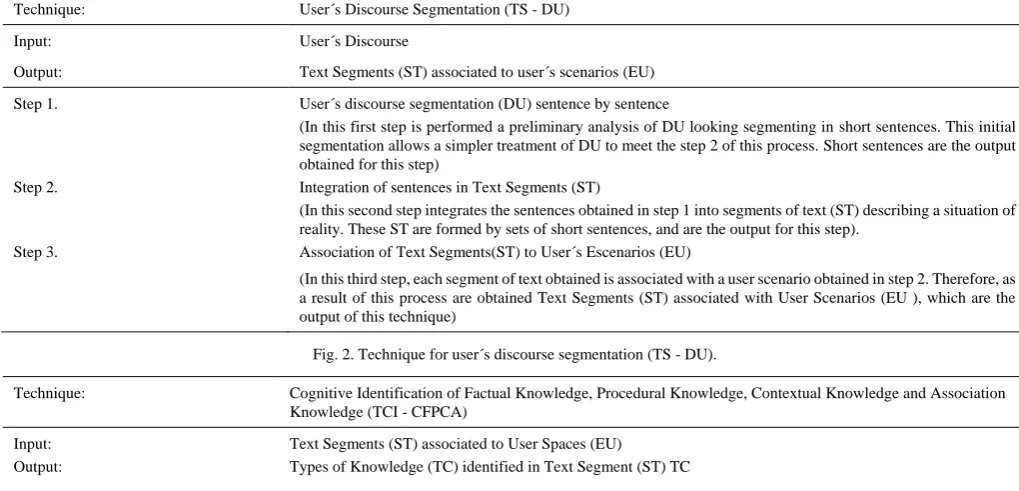
Technique: User´s Discourse Segmentation (TS - DU)
Input: User´s Discourse
Output: Text Segments (ST) associated to user´s scenarios (EU)
Step 1. User´s discourse segmentation (DU) sentence by sentence
(In this first step is performed a preliminary analysis of DU looking segmenting in short sentences. This initial segmentation allows a simpler treatment of DU to meet the step 2 of this process. Short sentences are the output obtained for this step)
Step 2. Integration of sentences in Text Segments (ST)
(In this second step integrates the sentences obtained in step 1 into segments of text (ST) describing a situation of reality. These ST are formed by sets of short sentences, and are the output for this step).
Step 3. Association of Text Segments(ST) to User´s Escenarios (EU)
(In this third step, each segment of text obtained is associated with a user scenario obtained in step 2. Therefore, as a result of this process are obtained Text Segments (ST) associated with User Scenarios (EU ), which are the output of this technique)
Fig. 2. Technique for user´s discourse segmentation (TS - DU).
Technique: Cognitive Identification of Factual Knowledge, Procedural Knowledge, Contextual Knowledge and Association Knowledge (TCI - CFPCA)
Input: Text Segments (ST) associated to User Spaces (EU)
Step 1. Identification of Types of Knowledge (TC) in Text Segments (ST)
(This step identifies the different types of knowledge: Contextual, Factual, Procedural and Association in the text segments (ST)).
1.1. Contextual Knowledge Identification in Text Segments (ST) 1.2. Factual Knowledge Identification in Text Segments (ST) 1.3. Procedural Knowledge Identification in Text Segments (ST) 1.4. Asociation Knowledge Identification in Text Segments (ST) Step 2. Integration among Text Segments and Types of Knowledge
(In this second step is necessary to integrate text segments (ST) with the types of knowledge identified in the respective ST; for which, drawing up a table indicating the various TC contained in each of the ST. Table conecting ST with respective identified TC is the output of this technique)
Fig. 3. Cognitive technique to identificate factual knowledge, procedural knowledge, contextual knowledge and association knowledge (TCD – EPEU).
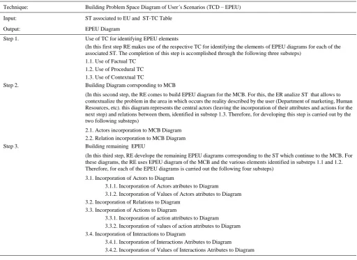
Technique: Building Problem Space Diagram of User´s Scenarios (TCD – EPEU)
Input: ST associated to EU and ST-TC Table
Output: EPEU Diagram
Step 1. Use of TC for identifying EPEU elements
(In this first step RE makes use of the respective TC for identifying the elements of EPEU diagrams for each of the associated ST. The completion of this step is accomplished through the following three substeps)
1.1. Use of Factual TC 1.2. Use of Procedural TC 1.3. Use of Contextual TC
Step 2. Building Diagram corrsponding to MCB
(In this second step, the RE comes to build EPEU diagram for the MCB. For this, the ER analize ST that allows to contextualize the problem in the area in which occurs the reality described by the user (Department of marketing, Human Resources, etc). this diagram represents the central actors (leaving the incorporation of their attributes and actions for the next step) and relations between them, identified in substep 1.3. Therefore, for developing this step is carried out by the two following substeps)
2.1. Actors incorporation to MCB Diagram 2.2. Relation incorporation to MCB Diagram Step 3. Building remaining EPEU
(In this third step, RE develope the remaining EPEU diagrams corresponding to the ST which continue to the MCB. For these diagrams, the RE uses EPEU diagram of the MCB and the various elements identified in substeps 1.1 and 1.2. Therefore, for each of the EPEU diagrams is carried out the following four substeps)
3.1. Incorporation of Actors to Diagram
3.1.1. Incorporation of Actors atributes to Diagram 3.1.2. Incorporation of Values of Actors atributes to Diagram 3.2. Incorporation of Relations to Diagram
3.3. Incorporation of Actions to Diagram
3.3.1. Incorporation of action attributes to Diagram 3.3.2. Incorporation of values of action attributes to Diagram 3.4. Incorporation of Interactions to Diagram
3.4.1. Incorporation of Interactions Atributes to Diagram 3.4.2. Incorporation of Values of Interactions Atributes to Diagram
Fig. 4. Technique for building the problem space diagram of user´s scenarios (TCD – EPEU).
V.
T
ECHNIQUESD
ESCRIPTION FORP
RODUCT-O
RIENTEDA
NALYSISThis
section
presents
techniques
for
Product
Oriented-Analysis, which are: Technique for Construction of
User´
s Scenarios Diagram (TCD-EU) to implement the task
of User´
s Scenario Development(CEU) (Fig. 5), Technique
for Refining User´
s Scenarios Diagram (TRD-EU) to
implement the task of User´
s Scenarios Diagram refinement
(REU) (Fig. 6) and Technique for Construction of Unified
User´
s Scenario Map Diagram (TCD-MUEU) for the
implementation of the construction task Unified User´
s
Scenarios Map (CMUEU) (Fig. 7).
Tecnique: Construction of User´s Scenario Diagram (TCD-EU)
Input: ST with association TC (from Table ST-TC) and EPEU Diagram
Output: EU Diagram
Step 1. Using Association TC
(In this first step, the ER uses the association CT for the construction of the EU. The completion of this step is performed by means of the following two substeps)
1.2. Actors Identification needed to carry out those functionalities Step 2. Construction of EPrEU diagram for each EPEU
(In this second step, the ER uses obtained functionalities and EPEU diagrams which were identified associated functionalities, to build the Space Product of User´s Scenario Diagram (EPrEU) for these EPEU. Therefore, the EPrEU diagrams with the respective functionalities are the output of this step)
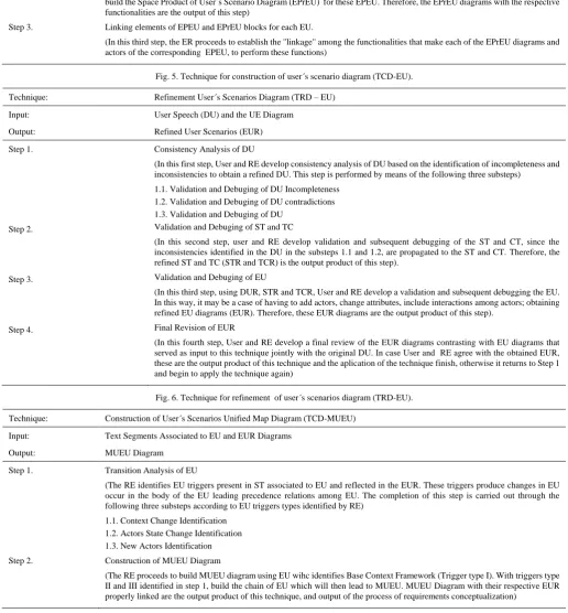
Step 3. Linking elements of EPEU and EPrEU blocks for each EU.
(In this third step, the ER proceeds to establish the "linkage" among the functionalities that make each of the EPrEU diagrams and actors of the corresponding EPEU, to perform these functions)
Fig. 5. Technique for construction of user´s scenario diagram (TCD-EU).
Technique: Refinement User´s Scenarios Diagram (TRD – EU)
Input: User Speech (DU) and the UE Diagram
Output: Refined User Scenarios (EUR)
Step 1. Consistency Analysis of DU
(In this first step, User and RE develop consistency analysis of DU based on the identification of incompleteness and inconsistencies to obtain a refined DU. This step is performed by means of the following three substeps)
1.1. Validation and Debuging of DU Incompleteness 1.2. Validation and Debuging of DU contradictions 1.3. Validation and Debuging of DU
Step 2. Validation and Debuging of ST and TC
(In this second step, user and RE develop validation and subsequent debugging of the ST and CT, since the inconsistencies identified in the DU in the substeps 1.1 and 1.2, are propagated to the ST and CT. Therefore, the refined ST and TC (STR and TCR) is the output product of this step).
Step 3. Validation and Debuging of EU
(In this third step, using DUR, STR and TCR, User and RE develop a validation and subsequent debugging the EU. In this way, it may be a case of having to add actors, change attributes, include interactions among actors; obtaining refined EU diagrams (EUR). Therefore, these EUR diagrams are the output product of this step).
Step 4. Final Revision of EUR
(In this fourth step, User and RE develop a final review of the EUR diagrams contrasting with EU diagrams that served as input to this technique jointly with the original DU. In case User and RE agree with the obtained EUR, these are the output product of this technique and the aplication of the technique finish, otherwise it returns to Step 1 and begin to apply the technique again)
Fig. 6. Technique for refinement of user´s scenarios diagram (TRD-EU).
Technique: Construction of User´s Scenarios Unified Map Diagram (TCD-MUEU)
Input: Text Segments Associated to EU and EUR Diagrams
Output: MUEU Diagram
Step 1. Transition Analysis of EU
(The RE identifies EU triggers present in ST associated to EU and reflected in the EUR. These triggers produce changes in EU occur in the body of the EU leading precedence relations among EU. The completion of this step is carried out through the following three substeps according to EU triggers types identified by RE)
1.1. Context Change Identification 1.2. Actors State Change Identification 1.3. New Actors Identification Step 2. Construction of MUEU Diagram
(The RE proceeds to build MUEU diagram using EU wihc identifies Base Context Framework (Trigger type I). With triggers type II and III identified in step 1, build the chain of EU which will then lead to MUEU. MUEU Diagram with their respective EUR properly linked are the output product of this technique, and output of the process of requirements conceptualization)
Fig. 7. Téchnique of construction of user´s scenarios unified map diagram (TCD-MUEU).
VI.
P
ARCIALC
ONCLUSIONS ANDF
UTURER
ESEARCHW
ORKThis paper introduces techniques for tasks for a two phases
process of requirements conceptualization. To carry out the
tasks it has been adapted some techniques and developed
another ones; they are: Protocol Analysis, Cognitive
Techniques for Identification of Factual Knowledge,
Procedural
Knowledge,
Contextual
Knowledge
and
Association Knowledge, and Technique of Construction of
out a systematic analysis of user's speech to reach gradually
an integrated representation of the fundamental elements of it.
The next research steps are: [a] develop field tests for the
validation of the introduced techniques, and [b] to explore
possible problems on techniques integration in the process of
requirements conceptualization.
A
CKNOWLEDGEMENTSThe research results reported in this article have been
partially funded by the Research Project 33A105,
Information Systems Research Group, Department of
Productive and Technological Development, National
University of Lanus (Argentine).
R
EFERENCES[1] I. Sommerville, “Software Engineering,” Addison-Wesley. 2005. [2] P. Chatzoglou and A. Soteriou, “A DEA framework to assess the
efficiency of the software requirements capture and analysis process,”
Decision-Sciences. vol. 30, no. 2, pp. 503-31. 1999.
[3] B. V. D. Vos, J. Gulla, and R. V. D. Riet, “Verification of conceptual models based in linguistic knowledge,” NLDB 1995
[4] P. Loucopoulos and V. Karakostas, “System requirements engineering,” McGraw-Hill, 1995.
[5] A. Davis, “Software requirements: Objects, functions and states,”
Prentice-Hall International. 1993.
[6] S. Faulk, “Software requirements: A tutorial,” in Software Engineering,
IEEE Computer Society Press, pp 82-101. 1997.
[7] A. Sutcliffe and N. Maiden, “Analysing the novice analyst: cognitive models in software engineering,” Intl. JL of Man-Machine Studies, vol. 36, no. 5. 1992.
[8] R. Wieringa, “Requirements engineering: Frameworks for understanding,” John Wiley. 1995.
[9] P. Jalote, “An integrated approach to software engineering,”
Springer-Verlag. 1997.
[10] N. Juristo and A. Moreno, “Introductory paper: Reflections on conceptual modeling,” Data and Knowledge Engineering, vol 33. 2000.
[11] A. Moreno, “Conceptual modelling method for software systems,” PhD on Computer Science Thesis. Polytechnic University of Madrid. 1999. [12] P. Chen, “Entity-relationship approach to data modeling,” in System
and Software Requirements Engineering, Thayer RH, Dorfman M (eds).