684
Design Of Standalone Pv System
Dheeban S S, Muthu Selvan N B, Senthil Kumar C
Abstract: The usage of conventional energy sources is being replaced by renewable energy sources. The solar energy is the most widely used renewable energy source. The solar energy can be harnessed from the sun with the help of photovoltaic panels. The photovoltaic panels can be configured to function as a standalone system or a grid-connected system. The standalone system is more reliable and easy for installation. The standalone system plays a major part in the rural electrification. This paper involves the mathematical modeling of the solar panels and analysis of the standalone system with a battery backup.
Index Terms: PV- photovoltaic, MPPT- Maximum Power Point Tracking, SOC- State of Charge, OCV- Open Circuit Voltage —————————— ——————————
1.
INTRODUCTION
Electrical energy has become a basic need in our day to day life. As the population of the country increases steadily, it becomes difficult for governments to provide people with basic electricity. In India, the government aims to provide all the villages with electricity. This vision of rural electrification can be achieved with the help of renewable energy resources like solar energy and wind energy. The solar energy installation cost is lower compared to that of wind energy. The grid integrated solar panel system has complexity in installation as the parameters of the grid and the PV system must be matching perfectly [11]. The main problem in a grid-connected PV system is the controllability of the system. The standalone PV system is easy to setup. The standalone system can be made to work efficiently with the help of a battery backup system.
2
SYSTEM
LAYOUT
The standalone PV system consists of an array of PV panels, power electronics converter, MPPT charge controller and a battery backup system [8]. The array of PV panels is used to harness the energy from the sun and it generates electric current [9]. The PV panels are arranged to generate the desired power. The output of the PV panel is fed to the converters. The power electronic converter used is of different topologies. The most commonly used topologies include boost converters, buck-boost converters [12]. These converters increase the reliability of the standalone PV system.The output of the converter is given directly to the load. The excess power can be stored using the battery backup system. The energy from the battery backup system can be used for future purpose. An MPPT charge controller is embedded along with the converter to track the maximum power point [9]. The overall layout of the standalone PV system is given in the below figure.
Fig. 1: System Layout of Standalone PV system
3
PV
PANELS
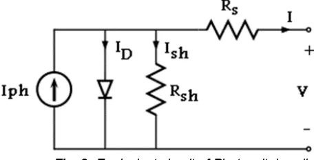
The photovoltaic panels are the main components in harnessing the energy from the sun. A single PV cell is fabricated to harness a small amount of solar energy. These PV cells can be clubbed together as a module or an array. The PV panels can be arranged in arrays to give the desired output power [2]. The equivalent circuit of the PV panels is given in the below diagram.
Fig. 2: Equivalent circuit of Photovoltaic cell
The PV panels can be mathematically modeled with the help of equations [1]. The following are the equations for modeling of the PV panels. The module photocurrent depends upon the irradiation of the solar energy over the panels and the operating temperature. These two characteristics determine the output of the solar photovoltaic module [1], [2]. The module photocurrent is given by the following equation.
Iph = Is + Ki ( T – 298 ) * λ/1000 (1)
where Is is the current through the series resistance in ampere,
Ki is a constant, ————————————————
Dheeban S S., M.E., is currently working as an Assistant Professor In Department of Electrical and Electronics Engineering in AAA College of Engineering and Technology Sivakasi, India, E-mail: [email protected].
Dr. N. B. Muthu Selvan., Ph.D., is currently working as an Associate Professor in the Department of Electrical and Electronics Engineering at SSN College of Engineering Chennai, India, E-mail: [email protected].
T is the temperature in Kelvin. The photogenerated current can be derived from the equivalent circuit by applying the Kirchoff's Current Law. As per Kirchoff's Current Law, The photocurrent produced is equal to the difference of the current from the photocell with the diode current and the shunt resistor current.
Iph = Iph – ID - Ish (2)
where Iph is the photo-generated current in ampere, ID is the diode current in ampere,
Ish is the current through the shunt resistor in ampere. The Schockley’s equation gives the expression for the reverse saturation current of the photovoltaic module.
Irs = Is / (exp(qVoc/ NskAT ) – 1 ) (3)
where Voc is the open-circuit voltage in volts,
q is the charge of the electron,
k is the Boltzmann constant. The environmental temperature is not a constant parameter and it varies periodically. The variation in temperature also affects the saturation current of the module.
Io = Irs [T/Tr]3exp [ q * Ego / Bk { 1/Tr – 1/ T} ] (4)
where Tr is the reference temperature, Ego is the bandgap energy between the conduction band and the valence band. The output current from the photovoltaic module is given by the following expression.
Ipv = Np * Iph – Np * Io (exp{q*(Vpv+Ipv*Rs)/NsAkT}-1) (5)
where A is the ideality factor usually taken as 1.6, Vpv is the voltage across the cell, Ipv is the output current in ampere, Io is the reverse saturation current in ampere. The required power from the PV panels can be harnessed by proper designing of the PV panels [1], [2]. The PV panels can be connected in series to increase the voltage level and can be connected in parallel to increase the current.
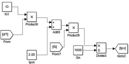
3.1 Simulink Model of PV Panel
The PV panels are modeled with the help of MATLAB-Simulink. The mathematical modeling of the PV panels is given in the below figures.
Fig. 3: MATLAB model for photocurrent Iph
Fig. 4: MATLAB model for Schockley’s Equation
Fig. 5: MATLAB model for saturation current
686
Fig. 7: MATLAB model of Equivalent circuit of PV cell
4 CONVERTERS
The converters can be of DC-DC converter or DC-AC converter based upon the application. The reliability of the standalone system is carried out by the converters. The DC-DC boost converter topology is the most widely used topology. The boost converter steps-up the input voltage to the desired level of voltage based upon the duty cycle [12], [2]. The equivalent circuit of the boost converter is given in the below diagram.
Fig. 8: Equivalent circuit diagram of a boost converter The operation of the boost converter is governed by the following equations.
Vi=Vs/(1+∝) (6)
where Vi is the output voltage and Vs is the input voltage. The boost converter works effectively in Continuous Conduction Mode. The inductance value must be higher in nature to make the converter to work in continuous conduction mode.
Lmin = ((1-∝)2∝ RL)/2fs (7)
where Lmin is the minimum inductance, ∝ is the duty cycle,
RL is the load resistance,
fs is the switching frequency of the IGBT. The minimum capacitance for the boost converter depends upon the amount of the ripple voltage Vr. The expression for the minimum capacitance is by the below expression.
Cmin = ∝/RL¬fsVr (8)
The load current Io is also dependent on the duty cycle.
Io= (1-∝)Is (9)
where Is is the source current.
The change in the current ∆I due to the value of inductance is given as
∆I = Vs(V1-Vs)/fsLV1 (10)
5 BATTERY
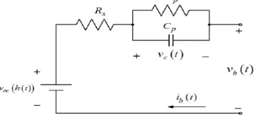
The PV standalone system makes use of the battery backup to provide uninterrupted power supply. The battery technology has been advancing. The battery size and shape has been drastically reduced but the capacity has increased. The lead-acid battery is one of the oldest and widely used batteries [3]. These batteries work on the electrochemical process. The batteries can be modeled dynamically using MATLAB-Simulink. The equivalent circuit of the battery is given in the below figure.
Fig. 9: Equivalent circuit of the battery
The battery characteristics can be determined by the two parameters Open Circuit Voltage (OCV) and State-of-Charge (SOC). State of Charge is the level of the battery relative to its capacity. The SOC determines the percentage for the battery at the time of charging. Open Circuit Voltage is the voltage of the battery during the equilibrium state. The value of Open Circuit Voltage depends upon the State of Charge [4]. The expression for the State of Charge is given in the below equation.
SOC = SOCo - ∫ ((100*I)/3600*αu)dt
where I is current, αu is the usable capacity and SOC 0 is the initial state of the battery. A charge controller is a device that limits the charging of the battery after reaching the required capacity. The excess current generated from the PV-panels is bypassed by the charge controllers. The MATLAB model of the overall system is given in the below figure.
Fig. 10: MATLAB Simulink model of Standalone PV system
5
RESULT
AND
DISCUSSION
Fig. 11: I-V characteristics of the PV panel
Fig. 12: P-V characteristics of PV panel
The maximum power point is tracked at the rated voltage of 17V and the power and the current reaches zero at the open-circuit voltage of 21V (VOC). The output from the PV panel is stepped up by the boost converter to 40V. The output voltage of the boost converter is given in the below figure.
Fig. 13: Boost converter output voltage
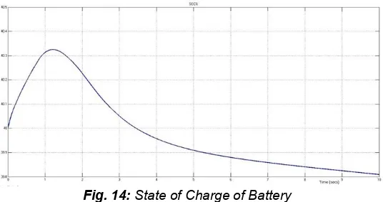
The system is backed up by a battery system. The State of Charging of the battery is given in the below figure.
Fig. 14: State of Charge of Battery
The above graph indicates the state of charge of the battery. The battery used for simulation purpose is a lead-acid battery. It is evident from the graph that the state of charge initially increases over a period of time and it decreases gradually. This model is very cost-effective and can be easily built up in remote areas.
6 CONCLUSION
Renewable energy is the future of the power industry. The standalone system structure along with the battery backup system has been presented in this paper. The standalone PV system is most widely used in rural electrification. The standalone PV systems are more useful in areas where the load is at the remote areas. In the future, the system range can be expanded coupling with backup system like diesel generator set. This makes the system to be a hybrid system. The battery system can also be replaced with the Li-ion battery to increase the durability.
REFERENCES
[1] N. Pandiarajan and Ranganath Muthu, ―Mathematical Modeling of Photovoltaic Module with Simulink‖, 2011 1st International Conference on Electrical Energy Systems.
[2] ―Grid Integration of 10kW Solar Panel‖, S. S. Dheeban ; V. Kamaraj, 3rd International Conference on Electrical Energy Systems (ICEES), 2016.
[3] M. Chen and G. A. Rincon-Mora, ―Accurate electrical battery model capable of predicting runtime and I-V performance,‖ IEEE Transactions on Energy Conversion, vol. 21, no. 2, pp. 504-511, June 2006.
688 modelling for PHEV applications,‖ IEEE Power and
Energy Society General Meeting, pp. 1-6, July 2010. [5] Z. Li, S. Kai, X. Yan, F. Lanlan, and G. Hongjuan, ―A
modular grid connected photovoltaic generation system based on DC bus,‖ IEEE TRANSACTIONS ON POWER ELECTRONICS,volume. 26, no. 2, pp. 523– 531, February. 2011.
[6] Marco Liserre a , Frede Blaabjerg b & Antonio Dell’Aquila,(2004) ―Step-by-step design procedure for a grid-connected three-phase PWM voltage source converter‖, International Journal of Electronics, 91:8, 445-460.
[7] S. M. Lukic, C. Jian, R. C. Bansal, F. Rodriguez, A. Emadi, "Energy Storage Systems for Automotive Applications", Industrial Electronics IEEE Transactions on, vol. 55, pp. 2258-2267, 2008.
[8] Ankit Varshney, Abu Tariq, "Simulink Model of Solar Array for Photo-voltaic Power Generation System", International Journal of Electronic and Electrical Engineering, vol. 7, no. 2, pp. 115-122, 2014.
[9] M.S. Sivagamasundari, P. Melba Mary, V.K. Velvizhi, "Maximum Power Point Tracking For Photovoltaic System by Perturb and Observe Method Using Buck Boost Converter" in International Journal of Advanced Research in Electrical Electronics and Instrumentation Engineering, vol. 2, no. 6, 2013.
[10] Huijuan Li, Yan Xu, "Real and reactive power control of a three — phase single stage PV system and PV voltage stability", IEEE journals, Feb 2012.
[11] Er. Mamatha Sandhu, Tilak Thakur, Mamatha Sandhu et al., "Issues Challenges Causes Impacts and Utilization of Renewable Energy Sources — Grid Integration", Int. Journal of Engineering Research and Applications, vol. 4, no. 3, pp. 636-643, March 2014, ISSN 2248-9622.